


1942 MARK-2
Table of contents
 Loading...
MARINE RADAR
MODEL
1932 MARK-2/1942 MARK-2

A
(
C
9-52, Ashihara-cho,
Nishinomiya, Japan
Telephone: 0798-65-2111
Telefax: 0798-65-4200
ll rights reserved.
Printed in Japan
Your Local Agent/Dealer
FIRST EDITION : AUG. 1998
C : APR. 3, 2001
PUB. No. OME-34620
YOSH)
MODEL1932/1942 MARK-2
SAFETY INSTRUCTIONS
DANGER
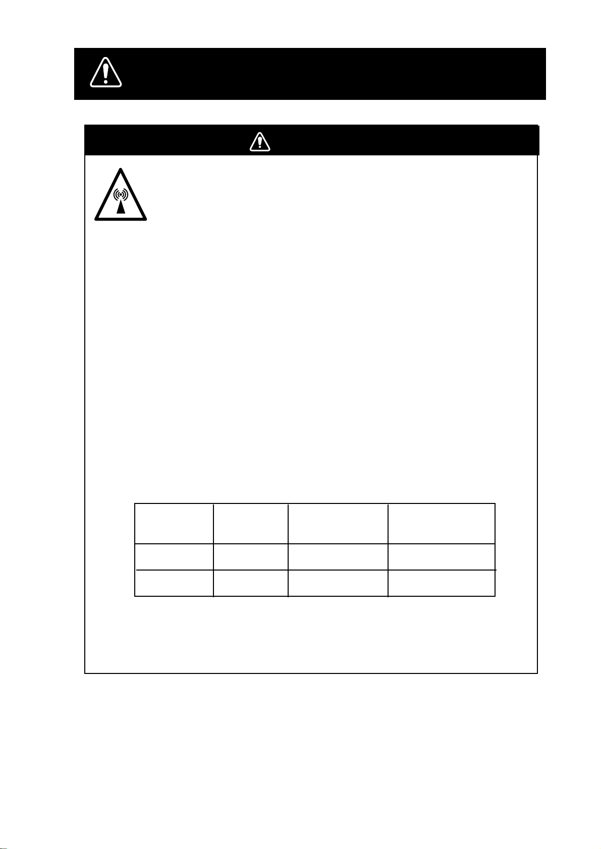
Stay away from transmitting scanner.
The radar scanner emits microwave radiation which can be harmful to the
human body, particularly the eyes. Never look directly into the scanner
radiator from a distance of less than 1 m when the radar is in operation.
Radio Frequency Radiation Hazard
The radar scanner emits electromagnetic radio frequency (RF) energy which can be
harmful, particularly to your eyes. Never look directly into the scanner aperture from a
close distance while the radar is in operation or expose yourself to the transmitting
scanner at a close distance.
point
2
exist are given in the table
Distance to
10 W/m2 point
Worst case 3.0 m
Worst case 2.5 m
Distances at which RF radiation levels of 100 and 10 W/m
below.
Note: If the scanner unit is installed at a close distance in front of the wheel house,
your administration may require halt of transmission within a certain sector of scanner
revolution. This is possible—Ask your FURUNO representative or dealer to provide
this feature.
MODEL
1932 MK-2
1942 MK-2
Radiator
type
XN10A
XN12A
Distance to
100 W/m
Worst case 0.2 m
2
Nil
i
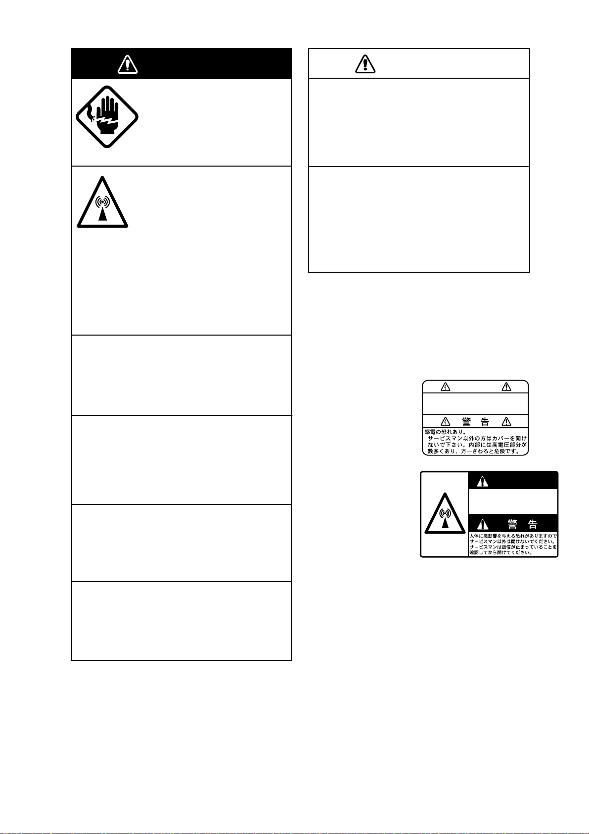
Two warning labels are attached to the display
unit and scanner unit. Do not remove these labels.
If labels are peeling off or are illegible, contact
a FURUNO agent or dealer.
WARNING
To avoid electrical shock, do not
remove cover. No user-serviceable
parts inside.
<Display Unit>
Name: Warning Label (1)
Type: 86-003-1011-0
Code no.: 100-236-230
WARNINGARNING
Radiation hazard. Only qualified
personnel should work inside scanner.
Confirm that TX has stopped before
opening scanner.
<Scanner Unit>
Name: Radiation Warning
Label
Type: 03-142-3201-0
Code no.: 100-266-890
WARNING
WARNING
CAUTIONCAUTION
Do not use the equipment for other than
its intended purpose.
Use of the equipment as a stepping stool,
for example, can result in personal injury
or equipment damage.
No one navigation device should ever be
solely replied upon for the navigation of
a vessel.
Always confirm position against all available
aids to navigation, for safety of vessel and
crew.
ELECTRICAL SHOCK HAZARD
Do not open the equipment.
Only qualified personnel
should work inside the
equipment.
Turn off the radar power
switch before servicing the
scanner unit. Post a warning sign near the switch
Do not disassemble or modify the
equipment.
indicating it should not be
turned on while the scanner
unit is being serviced.
Prevent the potential risk of
being struck by the rotating
scanner and exposure to
RF radiation hazard.
Fire, electrical shock or serious injury can
result.
Turn off the power immediately if water
leaks into the equipment or the equipment is emitting smoke or fire.
Continued use of the equipment can cause
fire or electrical shock.
Use the proper fuse.
Fuse rating is shown on the equipment.
Use of a wrong fuse can result in equipment
damage.
Keep heater away from equipment.
Heat can alter equipment shape and melt
the power cord, which can cause fire or
electrical shock.
ii

FOREWORD
Congratulations on your choice of the
FURUNO MODEL 1932/1942 MARK-2 Marine Radar . We are confident you will see why
the FURUNO name has become synonymous with quality and reliability.
For over 50 years FURUNO Electric Company has enjoyed an enviable reputation for
innovative and dependable marine electronics equipment. This dedication to excellence
is furthered by our extensive global network
of agents and dealers.
Your radar is designed and constructed to
meet the rigorous demands of the marine environment. However, no machine can perform its intended function unless properly
installed and maintained. Please carefully
read and follow the recommended procedures for, operation and maintenance.
We would appreciate hearing from you, the
end-user, about whether we are achieving
our purposes.
Thank you for considering and purchasing
FURUNO equipment.
Features
Your radar has a large variety of functions,
all contained in a remarkably small cabinet.
The main features of the MODEL 1932/1942
MARK-2 are:
¡ Traditional FURUNO reliability and qual-
ity in a compact, lightweight and low-cost
radar.
¡ Durable brushless scanner motor.
¡ On-screen alphanumeric readout of all op-
erational information.
¡ Standard features include EBL (Electronic
Bearing Line), VRM (Variable Range
Marker), Guard Alarm, Display Off Center, and Echo Trail.
¡ Watchman feature periodically transmits
the radar to check for radar targets which
may be entering the alarm zone.
¡ Ship’s position in latitude and longitude
and Loran C Time Dif ferences, range and
bearing to a waypoint, and ship’s speed/
heading/course can be shown in the bottom text area. (Requires a navigation aid
which can output such data in IEC 61162
format.)
¡ Zoom feature provided.
¡ Optional Auto Plotter ARP-10 acquires
and automatically tracks 5 targets plus 5
targets manually , or 10 targets manually.
iii

TABLE OF CONTENTS
FOREWORD.............................. iii
MENU TREE ............................... v
TABLE OF CONTENTS BY
INDICATION, MARKER............. vi
SYSTEM CONFIGURATION .... vii
1. PRINCIPLE OF OPERATION
1.1 What is Radar?............................... 1-1
1.2 How Ships Determined Position
Before Radar ................................. 1-1
1.3 How Radar Determines Range ...... 1-1
1.4 How Radar Determines Bearing..... 1-1
1.5 Radar W ave Speed and Scannner
Rotation Speed .............................. 1-1
1.6 The Radar Display ......................... 1-1
2. BASIC OPERATION
2.1 Control Description......................... 2-1
2.2 Turning the Radar On/Off............... 2-2
2.3 Transmitting.................................... 2-2
2.4 Stand-by......................................... 2-2
2.5 Selecting the Range....................... 2-3
2.6 Adjusting Picture Brilliance............. 2-3
2.7 Adjusting Receiver Sensitivity ........ 2-3
2.8 Adjusting the A/C SEA Control
(reducing sea clutter) ..................... 2-3
2.9 Adjusting the A/C RAIN Control
(reducing rain clutter)..................... 2-4
2.10 Erasing the Heading Marker,
North Marker................................ 2-5
2.11 Measuring the Range ................... 2-5
2.12 Measuring the Bearing................. 2-6
2.13 Using the Offset EBL.................... 2-6
2.14 Offcentering the Picture................ 2-7
2.15 Zoom ............................................ 2-8
3. MENU OPERATION
3.1 Basic Menu Operation.................... 3-1
3.2 Selecting the Presentation Mode ... 3-1
3.3 Magnifying Long Range Echoes
(echo stretch)................................. 3-2
3.4 Echo Trail ....................................... 3-2
3.5 Suppressing Radar Interference .... 3-3
3.6 Selecting Pulsewidth ...................... 3-4
3.7 Guard Alarm ................................... 3-4
3.8 Watchman ...................................... 3-5
3.9 Displaying Navigation Data............ 3-6
3.10 OTHER MENU Description.......... 3-7
3.11 Function Controls ......................... 3-8
3.12 Suppressing Noise ....................... 3-8
3.13 Adjusting Brilliance of Markers..... 3-8
3.14 Outputting Target Position............ 3-8
3.15 Dead Sector ................................. 3-8
4. FALSE ECHOES
4.1 Multiple Echoes.............................. 4-1
4.2 Side-lobe Echoes ........................... 4-1
4.3 Indirect Echoes .............................. 4-2
4.4 Blind and Shadow Sectors............. 4-2
4.5 SART (Search and Rescue
Transponder) ................................. 4-5
5. MAINTENANCE & TROUBLESHOOTING
5.1 Preventive Maintenance................. 5-1
5.2 Replacing the Fuse ........................ 5-1
5.3 T roubleshooting.............................. 5-2
5.4 Self Test.......................................... 5-3
5.5 Life Expectancy of Magnetron........ 5-3
6. OPERATION OF ARP-10
(OPTION)
6.1 General .......................................... 6-2
6.2 ARP-10 MENU Operation .............. 6-2
6.3 Acquiring T argets............................ 6-4
6.4 Displaying Target Data ................... 6-5
6.5 Mode and Length of Vectors .......... 6-6
6.6 Past Position Display...................... 6-6
6.7 Operational Warnings..................... 6-6
SPECIFICATIONS ................ SP-1
INDEX .....................................IN-1
Declaration of Conformity
(MODEL 1932 MARK-2)
Declaration of Conformity
iv
(MODEL 1942 MARK-2)
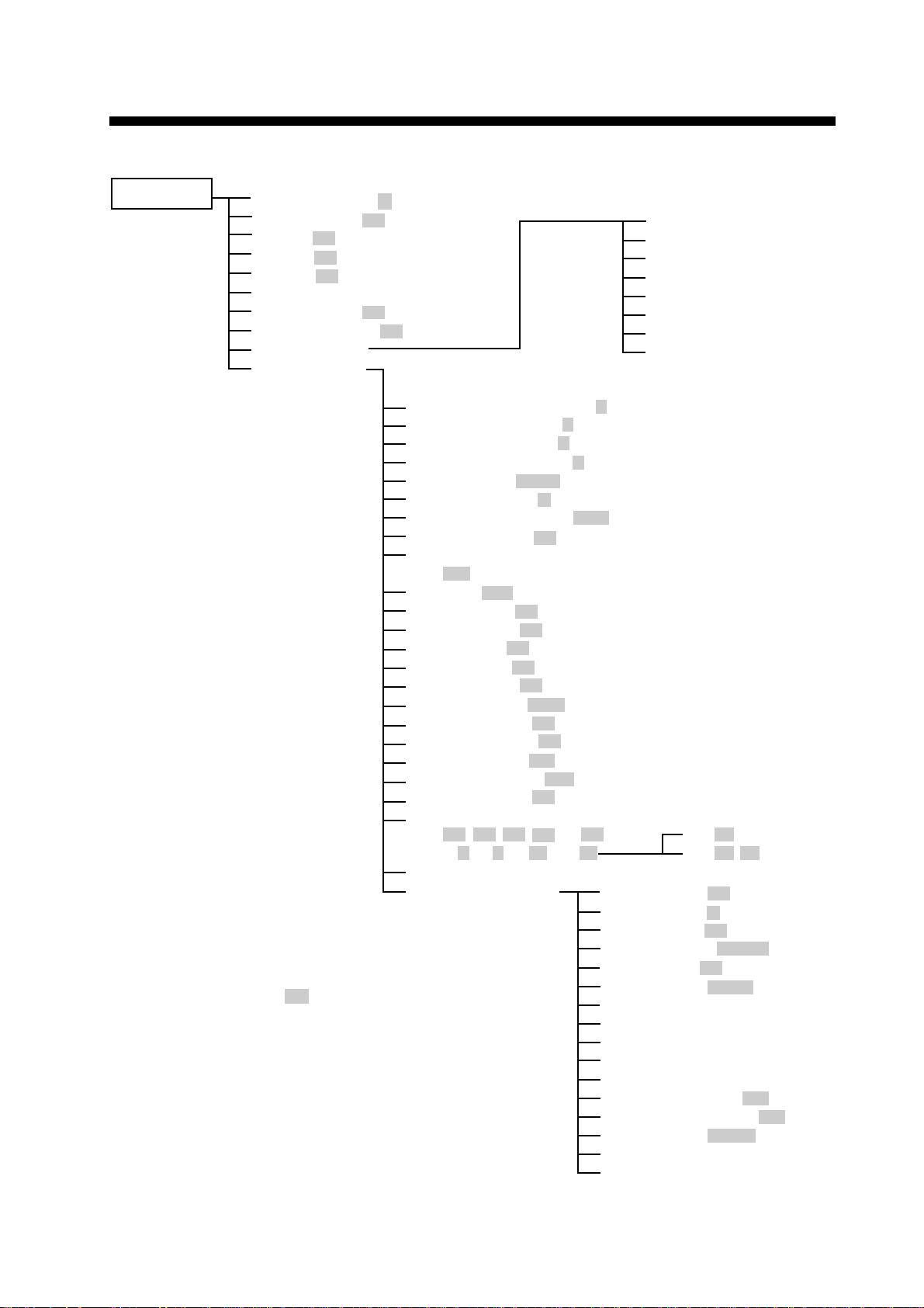
MENU TREE
MENU KEY
RINGS (Off, 1, 2, 3, max)
EBL OFFSET (Off, On)
SHIFT (Off, On)
ZOOM (Off, On)
MODE (HU, CU, NU, TM)
DISP DATA
ECHO TRAIL (Off, On)
ECHO STRTCH (Off, ES1, ES2)
ARP-10 MENU
OTHER MENU
Panel Dimmer (1, 2, 3, 4)
1.
Mark Brill (1, 2, 3, 4)
2.
HD Mark (1, 2, 3, 4)
3.
Characters (1, 2, 3, 4)
4.
Trail Tone (Single, Multi)
5.
Int Reject (Off, 1, 2, 3)
6.
Pulselength (Short, Long)
7.
Noise Reject (Off, On)
8.
Trail Time
9.
(15S, 30S, 1M, 3M, 6M, 15M, 30M, Cont)
Tune (Auto, Manu)
10.
Disp Data (Off, Nav, ARP, All)
11.
WPT Mark (Off, On)
12.
EBL Ref (Rel, True)
13.
VRM Unit (nm, km, sm)
14.
Watchman (Off, 5M, 10M, 20M)
15.
STBY DISP (Norm, Econo, Nav)
16.
Guard Mode (In, Out)
17.
Own Position (L/L, TD)
18.
Cursor Posi (B/R, L/L)
19.
Alm Sense LV (Low, Mid, High)
20.
Dead Sector (Off, On)
21.
Range
22.
(1/8, 1/4, 1/2, 3/4, 1, 1.5,
2, 3, 4, 6, 8, 12, 16, 24,
Self Test
23.
Installation Setup
24.
: Defaut settings
(Options)
1. Display
2. All Cancel
3. Vector ref
4. Vector Length
5. History
6. CPA SET
7. TCPA SET
8. AUTO ACQ
36, 48) :1932 M2
36, 48, 64) :1942 M2
1.
Nav Talker (All, GPS, LC)
2.
Depth Unit (m, fa, ft)
3.
Temp Unit (¡C, ¡F)
4.
Hdg Sensor (Magnet, Gyro)
5.
Key Beep (Off, On)
6.
Scan Stop (Rotate, Stop)
7.
Dead Sector
8.
Tune/Video Adjustment
9.
Heading Alignment
10.
Sweep Timing Adjustment
11.
MBS Adjustment
12.
Ant Height (Low, Mid, High)
13.
STC Curve (Sharp, Std, Gntl)
14.
Ope Mode (Master, Slave)
15.
Hours in Use
16.
TX Hours
v
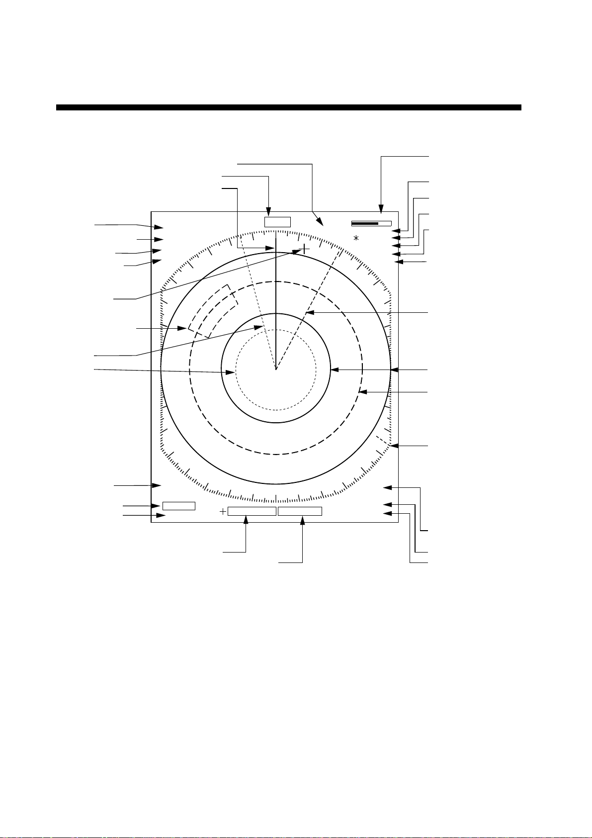
TABLE OF CONTENTS BY
INDICATION, MARKER
Echo trail elapsed time (P.3-3)
Heading (requires heading data)
Range (P.2-3)
Range ring interval (P.2-3)
Pulselength (P.2-3)
Display mode (P.3-1)
Cursor (P.2-5, 2-6)
Guard zone area (P.3-5)
EBL1 (P.2-6)
VRM1 (P.2-5)
Heading marker (P.2-5)
. 125
NM
.
0625
SP
HU
HDG 234.5¡
TRAIL
25 : 38
AUTO
30M
G (OUT)
ZOOM
ES1
OFFCENTER
Tuning indicator (P.3-7)
Echo trail time (P.3-3)
Guard Zone (P.3-4)
Zoom (P.2-8)
Echo Stretch (P.3-2)
Off center (P.2-7)
EBL2 (P.2-6)
Range ring (P.2-3, 2-5)
VRM2 (P.2-5)
A/C AUTO (P.2-4)
EBL1 bearing (P.2-6)
EBL2 bearing (P.2-6)
A/C
AUTO
EBL
345.6 R
¡
23.0 R
¡
Cursor bearing (P.2-6)
Cursor range (P.2-5)
13.5 R¡
0.142NM
North marker (P.2-5)
IR2
VRM
0.048NM
0.100NM
Interference rejector (P.3-3)
VRM1 range (P.2-5)
VRM2 range (P.2-5)
vi
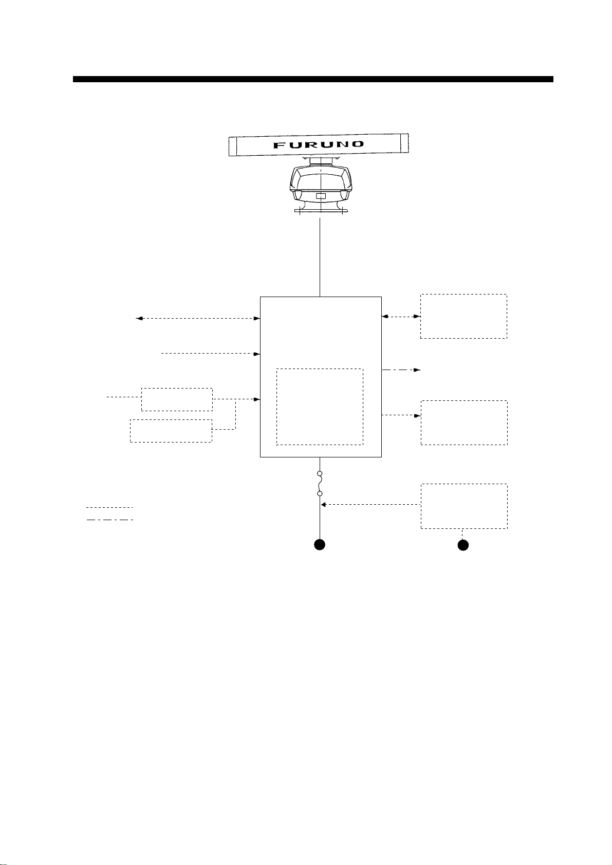
SYSTEM CONFIGURATION
Scanner Unit
MODEL 1932 MARK-2
XN10A-RSB-0070-064 (24 rpm)
XN10A-RSB-0073-064 (48 rpm)
MODEL 1942 MARK-2
XN12A-RSB-0070-059 (24 rpm)
XN12A-RSB-0073-059 (48 rpm)
Navigation
IEC 61162* (In/Out)
device
Video Sounder
Gyrocompass
*Equivalent to NMEA 0183
IEC 61162* (In/Out)
Gyro Converter
AD-100
Integrated Heading
Sensor PG-1000
: Option
: Local Supply
Display Unit
RDP-118
Auto Plotter
ARP-10
(24 rpm only)
12 VDC: 10A
24/32 VDC: 5A
12/24/32 VDC
Radar Plotter
RP-110
Remote Display
FMD-811/1800
External Alarm
Buzzer OP03-21
Rectifier
RU-3423
115/230 VAC
Note: Even though the display unit meets waterproof standard IPX-5, the connection of external buzzer, radar plotter and/or remote display can af fect waterproofness. W atertight integrity cannot be guaranteed. When these modification has been done, the display unit should
not be mounted where exposed.
vii

1. PRINCIPLE OF OPERATION
1.1 What is Radar?
The term “RADAR” is an acronym meaning
Radio Detection And Ranging. Although the
basic principles of radar were developed during World War II, echoes as an aid to navigation is not a new development.
1.2 How Ships Determined Position Before Radar
Before the invention of radar, when running
in fog near a rugged shoreline, ships would
sound a short blast on their whistles, fire a
shot, or strike a bell. The time between the
origination of the sound and the returning of
the echo indicated how far the ship was from
the cliffs or the shore. The direction from
which the echo was heard indicated the relative bearing of the shore.
1.3 How Radar Determines Range
1.4 How Radar Determines Bearing
The bearing to a target found by the radar is
determined by the direction in which the radar scanner is pointing when it emits an electronic pulse and then receives a returning
echo. Each time the scanner rotates pulses
are transmitted in the full 360 degree circle,
each pulse at a slightly different bearing from
the previous one. Therefore, if one knows the
direction in which the signal is sent out, one
knows the direction from which the echo must
return.
1.5 Radar Wave Speed and
Scanner Rotation Speed
Note that the speed of the radar waves out
to the target and back again as echoes is
extremely fast compared to the speed of rotation of the scanner. By the time radar echoes have returned to the scanner, the amount
of scanner rotation after initial transmission
of the radar pulse is extremely small.
Radar determines the distance to the target
by calculating the time difference between the
transmission of a radar signal and the reception of the reflected echo. It is a known fact
that radar waves travel at a nearly constant
speed of 162,000 nautical miles per second.
Therefore the time required for a transmitted
signal to travel to the target and return as an
echo to the source is a measure of the distance to the target. Note that the echo makes
a complete round trip, but only half the time
of travel is needed to determine the one-way
distance to the target. This radar automatically takes this into account in making the
range calculation.
1.6 The Radar Display
The range and bearing of a target is displayed
on what is called a Plan Position Indicator
(PPI). This display is essentially a polar diagram, with the transmitting ship’s position at
the center. Images of target echoes are received and displayed at their relative bearings, and at their distance from the PPI center.
With a continuous display of the images of
targets, the motion of the transmitting ship is
also displayed.
1-1
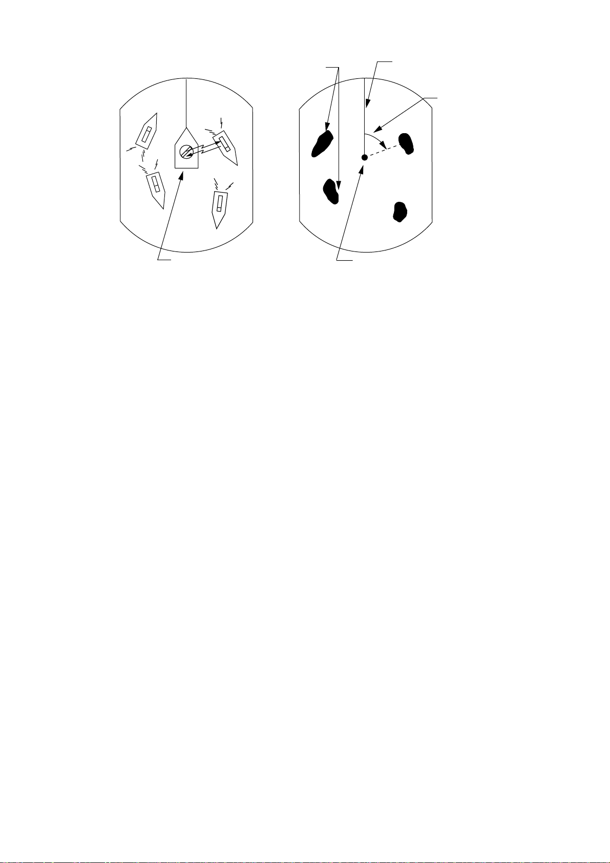
Targets
Heading marker
Range and bearing
of a target, relative
to own ship, are
A
D
A
readable on the PPI.
D
B
C
Own ship
(radar)
(A) Bird's eye view of situation
Figure 1-1 How radar works
B
C
Own ship
in center
(B) Radar picture of (A)
1-2
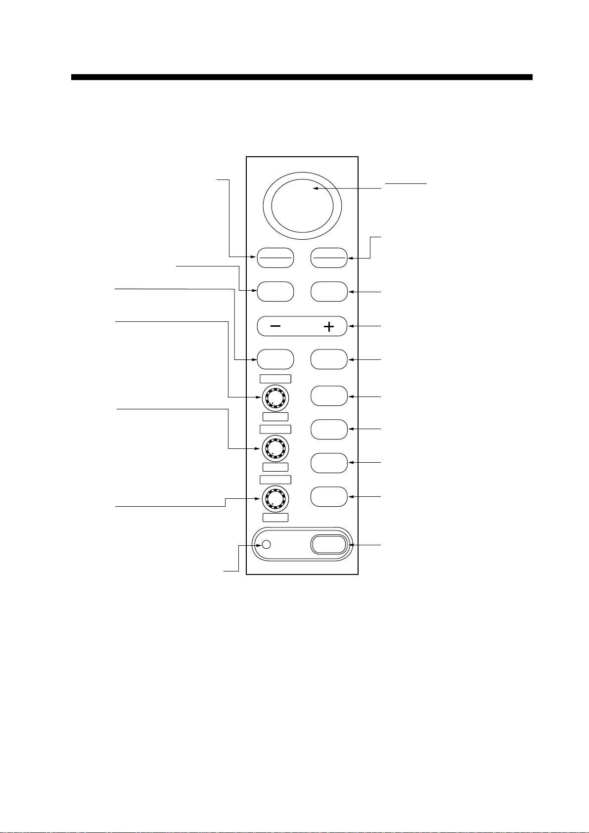
2.1 Control Description
2. BASIC OPERATION
Requires Auto Plotter ARP-10
Brief press:
Displays the data of target
selected with the cursor.
Long press:
Terminates plotting of the target
selected with the cursor.
Opens/closes menus.
Selects
EBL1/EBL2/VRM1/VRM2.
Control:
Adjusts sensitivity.
Switch:
Temporarily erases heading
marker (and north marker if
displayed).
Control:
Reduces sea clutter.
Switch*:
(Long press) Shifts your vessel s
position to cursor location.
(Brief press) Doubles size of
area between your vessel and
location selected by cursor.
Control:
Reduces rain clutter.
Switch*:
Displaces the EBL origin.
SELECT
CANCEL
MENU
RANGE
EBL/VRM
SELECT
GAIN
HM-OFF
A/C SEA
F1
A/C RAIN
F2
ACQ
ENTER
GUARD
EBL/VRM
CONTROL
TLL
A/C AUTO
BRILL
ST BY
TX
POWER
Omnipad
Shifts cursor, VRM and EBL;
selects items and options on
menu.
(1) Acquires the target selected
with the ominipad. (Requires
Auto Plotter ARP-10.)
(2) Registers selection on
menus.
Sets guard zone area.
Selects radar range.
Enables/erases
EBL1/EBL2/EBL3/EBL4.
Outputs target position data.
Automatically reduces sea and
rain clutters.
Adjusts display brilliance.
Sets radar in stand-by;
transmits radar pulse.
Turns power on/off.
Lights when the economy mode
is on.
*Default switch function.
Figure 2-1 Control panel
2-1
2.2 Turning the Radar On/Off
2.4 Stand-by
Press the [POWER] key to turn the radar on
or off.
The control panel lights and a timer displays
the time remaining for warm up of the magnetron (the device which produces radar
pulses), counting down from 1:30 to 0:01.
2.3 Transmitting
After the power is turned on and the magnetron has warmed up, STBY (Stand-By) appears at the screen center. This means the
radar is now fully operational.
Press the [STBY TX] key to transmit.
When transmitting, any echoes from targets
appear on the display. This radar displays
echoes in eight tones of green according to
echo strength.
When you won’t be using the radar for an
extended period, but you want to keep it in a
state of readiness, place it in stand-by by
pressing the [STBY TX] key. The display
shows “STBY,” navigation data, or goes into
the economy mode depending on menu setting. (More on menu operation later.)
Economy mode
The CRT can be set to automatically turn itself off when in stand-by, to reduce power
consumption. This feature is called the
“economy mode.” Power consumption in the
economy mode is 28 W. When the economy
mode is on, the lamp next to the [POWER]
key lights.
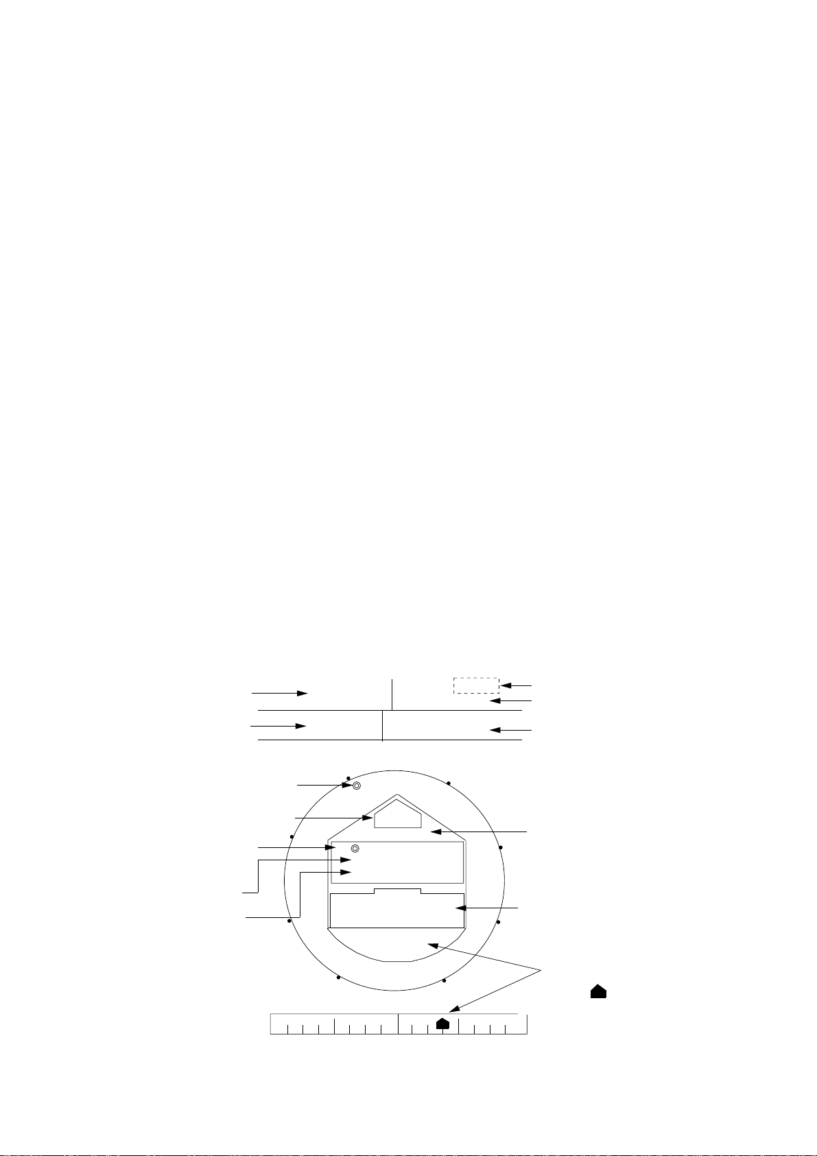
Navigation data display during
stand-by
If a navigation aid inputs navigation data to
this radar in IEC 61162 format, navigation
data can be displayed during stand-by. You
can turn the navigation data display on/off
through the menu. Figure 2-2 shows a typical navigation data display during stand-by.
Speed
Depth
TO Waypoint
bearing
Time-to-go to
TO Waypoint
Bearing to TO
Waypoint
Range to TO Waypoint
SPEED
10.5
kt
DEPTH TEMPERATURE
Heading
N
L
XTE
125
m
WPT TTG 01:08
BRG
RNG
LAT 30°00.00N
LON 135°00.00E
E
HDG
092.5°
CRS 180.0°M
45.0° M
12.0NM
OWN SHIP
TD 36378.1
59096.4
XTE
R 0.3NM
W
TRIP
000.3 nm
+17.3
ST-BY
°C
XTE
Figure 2-2 Typical navigation data display
during stand-by
Time-to-go to Stand-by
Trip distance since power on
Temperature
Course
S
Ship's position in latitude
and longitude and Loran
TDs
Cross Track Error
Mark " " shows
R
direction and amount of
error.
2-2

Note1: Availability of a particular display item
depends on incoming data.
2.7 Adjusting Receiver Sensitivity
Note2: When Range to Waypoint reaches 0.1
nm, the WPT marker jumps to dead ahead
even though a difference may exist between
heading and BRG to WPT.
Note3: When cross track error exceeds 1 nm
on either side, the XTE mark starts blinking.
2.5 Selecting the Range
The range selected automatically determines
the range ring interval, the number of range
rings, pulselength and pulse repetition rate,
for optimal detection capability in short to long
ranges.
Y ou can select which ranges and pulselength
(for 1.5 and 3 mile ranges) to use through
the menu. The range, range ring interval and
pulselength appear at the top left-hand corner of the display.
The [GAIN] control adjusts the sensitivity of
the receiver. It works in precisely the same
manner as the volume control of a broadcast
receiver, amplifying the signals received.
The proper setting is such that the background noise is just visible on the screen. If
you set up for too little sensitivity, weak echoes may be missed. On the other hand excessive sensitivity yields too much
background noise; strong targets may be
missed because of the poor contrast between
desired echoes and the background noise on
the display.
T o adjust receiver sensitivity , transmit on long
range, and adjust the [GAIN] control so background noise is just visible on the screen.
2.8 Adjusting the A/C SEA
Control
To select a range;
Press the [- RANGE +] key. The range and
range ring interval appear at the top left corner of the display.
Tips for selecting the range
¡ When navigating in or around crowded
harbors, select a short range to watch for
possible collision situations.
¡ If you select a lower range while on open
water, increase the range occasionally to
watch for vessels that may be heading
your way.
2.6 Adjusting Picture Brilliance
The [BRILL] key adjusts the brilliance of the
radar picture in sixteen levels. The current
level momentarily appears on the screen
whenever the [BRILL] key is pressed.
(reducing sea clutter)
Echoes from waves can be troublesome, covering the central part of the display with random signals known as “sea clutter.” The
higher the waves, and the higher the scanner above the water, the further the clutter
will extend. Sea clutter appears on the display as many small echoes which might affect radar performance. (See the left-hand
figure in Figure 2-3.) When sea clutter masks
the picture, adjust the [A/C SEA] control to
reduce the clutter.
How the A/C SEA control works
The [A/C SEA] control reduces the amplification of echoes at short ranges (where clutter is the greatest) and progressively
increases amplification as the range increases, so amplification will be normal at
those ranges where there is no sea clutter.
2-3
Loading...