


 Loading...
Furuno 1742c, 1752c, 1762, 1762c, 1742 User Manual
...MARINE RADAR
MODEL1722/1732/1742/1752/1762
MODEL1722C/1732C/1742C/1752C/1762C

C
9 - 5 2 , A s h i h a r a - c h o , N i s h i n o m i y a , J a p a n
T e l e p h o n e : |
0 7 9 8 |
- 6 5 |
- 2111 |
T e l e f a x : |
0 7 9 8 - 6 5 - 4 2 0 0 |
||
A l l r i g h t s r e s e r v e d . Printed in Japan
|
P U B . N o . O M E -3 4 9 4 0 |
( H I M A D |
M O D E L 1 7 2 2 / C S E R I E S |
 Y o u r L o c a l A g e n t / D e a l e r
F I R S T E D I T I O N : |
A P R . 2 0 0 1 |
|
E 1 |
: |
M A Y 1 7 , 2 0 0 2 |

 SAFETY INSTRUCTIONS
 WARNING
ELECTRICAL SHOCK HAZARD
Do not open the equipment.
Only qualified personnel should work inside the equipment.
Do not disassemble or modify the equipment.
Fire, electrical shock or serious injury can result.
Immediately turn off the power at the switchboard if the equipment is emitting smoke or fire.
Continued use of the equipment can cause fire or electrical shock. Contact a FURUNO agent for service.
Keep heater away from equipment.
A heater can melt the equipment's power cord, which can cause fire or electrical shock.
Use the proper fuse.
Fuse rating is shown on the equipment. Use of a wrong fuse can result in damage to the equipment.
 CAUTION
A warning label is attached to the equipment. Do not remove the label. If the label is missing or damaged, contact
a FURUNO agent or dealer about replacement.
WARNING |
Name: Warning Label (1) |
|
Type: 86-003-1011-0 |
||
To avoid electrical shock, do not |
||
remove cover. No user-serviceable |
Code No.: 100-236-230 |
|
parts inside. |
|
 WARNING
Radio Frequency
Radiation Hazard
The radar antenna emits electromagnetic radio frequency (RF) energy which can be harmful, particularly to your eyes. Never look directly into the antenna aperture from a close distance while the radar is in operation or expose yourself to the transmitting antenna at a close distance.
Distances at which RF radiation levels of 100 and 10 W/m2 exist are given in the table below.
Note: If the antenna unit is installed at a close distance in front of the wheel house, your administration may require halt of transmission within a certain sector of antenna revolution. This is possible - Ask your FURUNO representative or dealer to provide this feature.
MODEL |
Distance to |
Distance to |
|
100 W/m2 |
10 W/m2 |
||
|
point |
point |
|
|
|
|
|
1722 |
Nil |
Worst case |
|
0.50 m |
|||
|
|
||
|
|
|
|
1732 |
Nil |
Worst case |
|
|
0.50 m |
||
|
|
||
|
|
|
|
1742 |
Nil |
Worst case |
|
1.00 m |
|||
|
|
||
|
|
|
|
1752 |
0.15 m |
Worst case |
|
|
2.00 m |
||
|
|
||
|
|
|
|
1762 |
0.20 m |
Worst case |
|
3.00 m |
|||
|
|
||
|
|
|
 CAUTION
No one navigation device should ever be solely replied upon for the navigation of a vessel.
Always confirm position against all available aids to navigation, for safety of vessel and crew.
i
TABLE OF CONTENTS
|
|
|
......................................................................................................FOREWORD |
viii |
|
SYSTEM CONFIGURATIONS .............................................................................. |
x |
|
1. OPERATIONAL OVERVIEW ......................................................................... |
1-1 |
|
1.1 |
Operating Controls ...................................................................................................... |
1-2 |
|
1.1.1 Display unit controls ......................................................................................... |
1-2 |
|
1.1.2 Remote controller ............................................................................................. |
1-5 |
1.2 |
Inserting a Chart Card ................................................................................................. |
1-6 |
1.3 |
Turning the Unit On/Off................................................................................................ |
1-7 |
1.4 |
Cursor Pad, Cursor...................................................................................................... |
1-8 |
1.5 |
Display Brilliance, Panel Brilliance, Contrast, Hue ....................................................... |
1-9 |
|
1.5.1 Display brilliance, panel brilliance ..................................................................... |
1-9 |
|
1.5.2 Contrast........................................................................................................... |
1-10 |
|
1.5.3 Hue (MODEL1722C series)............................................................................. |
1-10 |
1.6 |
Selecting a Display ..................................................................................................... |
1-11 |
|
1.6.1 Display modes................................................................................................. |
1-11 |
|
1.6.2 Selecting a display .......................................................................................... |
1-12 |
|
1.6.3 Switching control in combination and overlay screens ..................................... |
1-13 |
|
1.6.4 Selecting radar source..................................................................................... |
1-14 |
1.7 |
Data Boxes................................................................................................................. |
1-15 |
|
1.7.1 Showing, hiding data boxes with soft key ........................................................ |
1-15 |
|
1.7.2 Rearranging data boxes .................................................................................. |
1-15 |
|
1.7.3 Temporarily erasing a data box........................................................................ |
1-15 |
1.8 |
Function Keys............................................................................................................. |
1-16 |
|
1.8.1 Executing a function ........................................................................................ |
1-16 |
1.9 |
Simulation Display ...................................................................................................... |
1-17 |
2. RADAR OPERATION..................................................................................... |
2-1 |
|
2.1 |
Radar Display.............................................................................................................. |
2-1 |
2.2 |
Transmitting, Stand-by................................................................................................. |
2-2 |
2.3 |
Tuning ......................................................................................................................... |
2-2 |
2.4 |
Adjusting the Gain ....................................................................................................... |
2-2 |
2.5 |
Reducing Sea Clutter .................................................................................................. |
2-4 |
|
2.5.1 How the A/C SEA works................................................................................... |
2-4 |
|
2.5.2 Adjusting A/C SEA ........................................................................................... |
2-4 |
2.6 |
Reducing Precipitation Clutter ..................................................................................... |
2-5 |
|
2.6.1 Adjusting the A/C RAIN .................................................................................... |
2-5 |
|
2.6.2 Adjusting the FTC............................................................................................. |
2-6 |
2.7 |
Range Scale................................................................................................................ |
2-7 |
2.8 |
Pulselength.................................................................................................................. |
2-8 |
ii
2.9 Presentation Mode....................................................................................................... |
2-9 |
|
|
2.9.1 Selecting a presentation mode.......................................................................... |
2-9 |
|
2.9.2 Description of presentation modes.................................................................. |
2-10 |
2.10 |
Measuring the Range............................................................................................... |
2-12 |
|
2.10.1 Measuring range by range rings.................................................................... |
2-12 |
|
2.10.2 Measuring range by cursor ........................................................................... |
2-13 |
|
2.10.3 Measuring range by VRM ............................................................................. |
2-14 |
|
2.10.4 Erasing a VRM, VRM indication .................................................................... |
2-15 |
|
2.10.5 Erasing EBL/VRM data boxes....................................................................... |
2-15 |
|
2.10.6 Hiding EBL/VRM data boxes......................................................................... |
2-15 |
|
2.10.7 Moving EBL/VRM data boxes ....................................................................... |
2-15 |
2.11 Measuring the Bearing ............................................................................................. |
2-15 |
|
|
2.11.1 Measuring bearing by cursor ......................................................................... |
2-15 |
|
2.11.2 Measuring bearing by EBL ............................................................................ |
2-15 |
|
2.11.3 Erasing an EBL, EBL indication..................................................................... |
2-16 |
|
2.11.4 Erasing EBL/VRM data boxes ....................................................................... |
2-16 |
|
2.11.5 Hiding EBL/VRM data boxes ......................................................................... |
2-16 |
|
2.11.6 Moving EBL/VRM data boxes........................................................................ |
2-16 |
2.12 |
Erasing the Heading Line, North Marker .................................................................. |
2-17 |
2.13 |
Reducing Noise........................................................................................................ |
2-17 |
2.14 |
Reducing Radar Interference ................................................................................... |
2-18 |
2.15 |
Zoom ....................................................................................................................... |
2-19 |
|
2.15.1 Zooming in on radar targets .......................................................................... |
2-19 |
|
2.15.2 Zooming ARP, TTM targets........................................................................... |
2-19 |
2.16 |
Shifting the Picture................................................................................................... |
2-20 |
|
2.16.1 Manual shift .................................................................................................. |
2-20 |
|
2.16.2 Automatic shift .............................................................................................. |
2-21 |
2.17 |
Using the Offset EBL................................................................................................ |
2-22 |
|
2.17.1 Predicting a collision course.......................................................................... |
2-22 |
|
2.17.2 Measuring range & bearing between two targets .......................................... |
2-23 |
2.18 |
Echo Trails ............................................................................................................... |
2-24 |
|
2.18.1 Trail time ....................................................................................................... |
2-24 |
|
2.18.2 Starting echo trails ........................................................................................ |
2-25 |
|
2.18.3 Trail brilliance (MODEL1722 series).............................................................. |
2-25 |
|
2.18.4 Trail gradation (MODEL1722C series) .......................................................... |
2-25 |
|
2.18.5 Trail color (MODEL1722C series) ................................................................. |
2-26 |
2.19 |
Echo Stretch ............................................................................................................ |
2-27 |
2.20 |
Echo Averaging........................................................................................................ |
2-28 |
2.21 |
Outputting TLL Data................................................................................................. |
2-29 |
2.22 |
Guard Alarm............................................................................................................. |
2-30 |
|
2.22.1 Setting a guard alarm zone ........................................................................... |
2-30 |
|
2.22.2 When the alarm is violated… ........................................................................ |
2-31 |
|
2.22.3 Canceling the guard alarm ............................................................................ |
2-31 |
2.23 Watchman................................................................................................................ |
2-32 |
|
|
2.23.1 How watchman works ................................................................................... |
2-32 |
|
2.23.2 Turning on/off watchman............................................................................... |
2-32 |
|
2.23.3 Setting watchman stand-by interval .............................................................. |
2-32 |
2.24 Waypoint Marker ...................................................................................................... |
2-33 |
|
iii
2.25 ARP (option), TTM operation .................................................................................... |
2-34 |
2.25.1 Activating/deactivating ARP, TTM.................................................................. |
2-35 |
2.25.2 Acquiring and tracking targets (ARP only) ..................................................... |
2-36 |
2.25.3 Displaying target number (internal, external ARP) ......................................... |
2-37 |
2.25.4 Terminating tracking of ARP targets .............................................................. |
2-38 |
2.25.5 Setting vector attributes (ARP) ...................................................................... |
2-39 |
2.25.6 Displaying past position display (ARP) .......................................................... |
2-40 |
2.25.7 ARP, TTM target data .................................................................................... |
2-41 |
2.25.8 CPA/TCPA alarm (ARP) ................................................................................ |
2-42 |
2.25.9 Lost target alarm (ARP)................................................................................. |
2-43 |
2.26 Interpreting the Radar Display .................................................................................. |
2-44 |
2.26.1 General ......................................................................................................... |
2-44 |
2.26.2 False echoes ................................................................................................. |
2-46 |
2.26.3 SART (Search and Rescue Transponder) ..................................................... |
2-48 |
2.26.4 Racon (Radar Beacon).................................................................................. |
2-50 |
3. PLOTTER OPERATION................................................................................. |
3-1 |
3.1 Plotter Displays............................................................................................................ |
3-1 |
3.1.1 Full-screen plotter display................................................................................. |
3-1 |
3.1.2 Compass display .............................................................................................. |
3-3 |
3.1.3 Highway display ............................................................................................... |
3-5 |
3.1.4 Nav data display............................................................................................... |
3-6 |
3.2 Presentation Mode ...................................................................................................... |
3-7 |
3.2.1 North-up ........................................................................................................... |
3-7 |
3.2.2 Course-up ........................................................................................................ |
3-8 |
3.2.3 Auto course-up ................................................................................................. |
3-8 |
3.3 Shifting the Display...................................................................................................... |
3-9 |
3.4 Chart Scale.................................................................................................................. |
3-9 |
3.5 Chart Cards ................................................................................................................ |
3-10 |
3.5.1 Chart card overview......................................................................................... |
3-10 |
3.5.2 Indices and chart enlargement ........................................................................ |
3-11 |
3.5.3 FURUNO and NavCharts™............................................................................. |
3-12 |
3.5.4 C-MAP cards ................................................................................................... |
3-14 |
3.6 Working with Track ..................................................................................................... |
3-18 |
3.6.1 Displaying track ............................................................................................... |
3-18 |
3.6.2 Stopping, restating plotting of own ship track................................................... |
3-19 |
3.6.3 Changing track color (MODEL1722C series)................................................... |
3-20 |
3.6.4 Track plotting method and interval for own ship track ...................................... |
3-21 |
3.6.5 Changing own ship track/mark distribution setting ........................................... |
3-22 |
3.6.6 Erasing track ................................................................................................... |
3-23 |
3.7 Marks, Lines ............................................................................................................... |
3-25 |
3.7.1 Entering a mark ............................................................................................... |
3-25 |
3.7.2 Changing mark attributes ................................................................................ |
3-25 |
3.7.3 Selecting line type ........................................................................................... |
3-26 |
3.7.4 Erasing marks, lines ........................................................................................ |
3-27 |
3.8 Waypoints................................................................................................................... |
3-29 |
3.8.1 Entering waypoints .......................................................................................... |
3-29 |
3.8.2 Editing waypoint data ...................................................................................... |
3-32 |
iv
3.8.3 Erasing waypoints........................................................................................... |
3-34 |
3.8.4 Changing waypoint mark size (FURUNO, NavCharts™)................................. |
3-35 |
3.8.5 Searching waypoints....................................................................................... |
3-36 |
3.9 Routes ....................................................................................................................... |
3-37 |
3.9.1 Creating routes ............................................................................................... |
3-37 |
3.9.2 Connecting routes........................................................................................... |
3-41 |
3.9.3 Inserting waypoints ......................................................................................... |
3-42 |
3.9.4 Removing waypoints from a route................................................................... |
3-44 |
3.9.5 Erasing routes................................................................................................. |
3-44 |
3.10 Navigation................................................................................................................ |
3-45 |
3.10.1 Navigating to a "quick point" ......................................................................... |
3-45 |
3.10.2 Navigating to waypoints ................................................................................ |
3-46 |
3.10.3 Navigating to ports, port services (NavCharts™ only) ................................... |
3-47 |
3.10.4 Following a route........................................................................................... |
3-49 |
3.11 Alarms .................................................................................................................... |
3-53 |
3.11.1 Audio alarm on/off ......................................................................................... |
3-53 |
3.11.2 Arrival alarm.................................................................................................. |
3-54 |
3.11.3 Anchor watch alarm ...................................................................................... |
3-55 |
3.11.4 XTE (Cross Track Error) alarm ...................................................................... |
3-56 |
3.11.5 Speed alarm.................................................................................................. |
3-56 |
3.11.6 Proximity alarm ............................................................................................. |
3-57 |
3.11.7 Trip alarm...................................................................................................... |
3-58 |
3.11.8 Alarm information .......................................................................................... |
3-59 |
3.12 Resetting Trip Distance ............................................................................................ |
3-60 |
3.13 Entering the MOB Mark, Setting MOB as Destination .............................................. |
3-61 |
4. VIDEO SOUNDER OPERATION ................................................................... |
4-1 |
|
4.1 |
Principle of Operation................................................................................................... |
4-1 |
4.2 |
Sounder Displays......................................................................................................... |
4-2 |
|
4.2.1 Selecting a sounder display .............................................................................. |
4-2 |
|
4.2.2 Description of sounder displays ........................................................................ |
4-3 |
|
4.2.3 Selecting screen split method in combination displays...................................... |
4-7 |
4.3 |
Automatic Sounder Operation ...................................................................................... |
4-8 |
|
4.3.1 How the automatic sounder works .................................................................... |
4-8 |
|
4.3.2 Types of automatic sounder modes .................................................................. |
4-8 |
|
4.3.3 How to enable automatic sounder operation ..................................................... |
4-8 |
4.4 |
Manual Sounder Operation .......................................................................................... |
4-9 |
|
4.4.1 Selecting the manual mode............................................................................... |
4-9 |
|
4.4.2 Selecting display range..................................................................................... |
4-9 |
|
4.4.3 Adjusting the gain ............................................................................................. |
4-9 |
|
4.4.4 Range shifting................................................................................................. |
4-10 |
4.5 |
Measuring Depth, Time.............................................................................................. |
4-11 |
4.6 |
Reducing Interference................................................................................................ |
4-12 |
4.7 |
Reducing Low Level Noise......................................................................................... |
4-13 |
4.8 |
Erasing Weak Echoes .............................................................................................. |
4-14 |
4.9 White Marker (MODEL1722C series)......................................................................... |
4-15 |
|
v
4.10 Picture Advance Speed ............................................................................................ |
4-16 |
4.10.1 Advancement independent of ship’s speed.................................................... |
4-16 |
4.10.2 Advancement synchronized with ship’s speed............................................... |
4-17 |
4.11 Display Colors (MODEL1722C series) ...................................................................... |
4-18 |
4.12 Alarms ...................................................................................................................... |
4-19 |
4.12.1 Audio alarm on/off ......................................................................................... |
4-19 |
4.12.2 Bottom alarm ................................................................................................. |
4-20 |
4.12.3 Fish alarm ..................................................................................................... |
4-20 |
4.12.4 Fish alarm (B/L)............................................................................................. |
4-21 |
4.12.5 Water temperature alarm............................................................................... |
4-22 |
4.12.6 When an alarm setting is violated... ............................................................... |
4-23 |
4.13 Water Temperature Graph ........................................................................................ |
4-24 |
4.14 Interpreting the Sounder Display............................................................................... |
4-25 |
4.14.1 Zero line ........................................................................................................ |
4-25 |
4.14.2 Bottom echo .................................................................................................. |
4-25 |
4.14.3 Fish school echoes........................................................................................ |
4-26 |
4.14.4 Surface noise/Aeration .................................................................................. |
4-26 |
5. CUSTOMIZING YOUR UNIT.......................................................................... |
5-1 |
|
5.1 |
Generic Setup ............................................................................................................. |
5-1 |
5.2 |
Radar Setup ................................................................................................................ |
5-3 |
|
5.2.1 Radar display setup.......................................................................................... |
5-3 |
|
5.2.2 Radar range setup............................................................................................ |
5-6 |
|
5.2.3 Function key setup ........................................................................................... |
5-7 |
5.3 |
Plotter Setup................................................................................................................ |
5-9 |
|
5.3.1 Navigation options............................................................................................ |
5-9 |
|
5.3.2 Function key setup .......................................................................................... |
5-10 |
5.4 |
Chart Setup ................................................................................................................ |
5-12 |
|
5.4.1 Chart offset...................................................................................................... |
5-12 |
|
5.4.2 FURUNO, Nav-Charts™ chart attributes ......................................................... |
5-13 |
|
5.4.3 C-MAP chart attributes .................................................................................... |
5-16 |
5.5 |
Data Boxes Setup....................................................................................................... |
5-20 |
5.6 |
Hot Page Setup .......................................................................................................... |
5-21 |
5.7 |
Navigator Setup.......................................................................................................... |
5-23 |
|
5.7.1 Navigation data source.................................................................................... |
5-23 |
|
5.7.2 GPS receiver setup (Set equipped with GP-310B/320B) ................................. |
5-24 |
|
5.7.3 TD display setup.............................................................................................. |
5-27 |
5.8 |
Nav Data Display Setup.............................................................................................. |
5-29 |
5.9 |
Sounder Setup............................................................................................................ |
5-30 |
|
5.9.1 System setup................................................................................................... |
5-30 |
|
5.9.2 Sensor setup ................................................................................................... |
5-32 |
|
5.9.3 Sounding range, zoom range, bottom lock range ............................................ |
5-33 |
|
5.9.4 Function key setup .......................................................................................... |
5-34 |
vi
6. DATA TRANSFER.......................................................................................... |
6-1 |
|
6.1 |
Memory Card Operations............................................................................................. |
6-1 |
|
6.1.1 Formatting memory cards ................................................................................. |
6-1 |
|
6.1.2 Saving data to a memory card .......................................................................... |
6-2 |
|
6.1.3 Playing back data from a memory card............................................................. |
6-4 |
6.2 |
Uploading, Downloading Data...................................................................................... |
6-5 |
|
6.2.1 Setting communication software on the PC....................................................... |
6-5 |
|
6.2.2 Uploading or downloading data......................................................................... |
6-5 |
6.3 |
Loading Waypoint Data from Yeoman .......................................................................... |
6-8 |
6.4 |
Receiving Data Via Network Equipment....................................................................... |
6-9 |
6.5 Outputting Data Through the Network........................................................................ |
6-10 |
|
7. MAINTENANCE, TROUBLESHOOTING |
...................................................... 7-1 |
|
7.1 |
Preventive Maintenance............................................................................................... |
7-1 |
7.2 |
Replacement of Fuse ................................................................................................... |
7-2 |
7.3 |
Replacement of Battery................................................................................................ |
7-2 |
7.4 Simple Troubleshooting................................................................................................ |
7-3 |
|
|
7.4.1 General............................................................................................................. |
7-3 |
|
7.4.2 Radar................................................................................................................ |
7-4 |
|
7.4.3 Plotter ............................................................................................................... |
7-5 |
|
7.4.4 Sounder ............................................................................................................ |
7-6 |
7.5 |
Diagnostics .................................................................................................................. |
7-7 |
|
7.5.1 Memory I/O test ................................................................................................ |
7-7 |
|
7.5.2 Test pattern..................................................................................................... |
7-10 |
|
7.5.3 Keyboard, remote controller test ..................................................................... |
7-11 |
7.6 GPS Status Display ................................................................................................... |
7-12 |
|
7.7 |
Clearing Memories..................................................................................................... |
7-13 |
7.8 |
Error Messages.......................................................................................................... |
7-14 |
APPENDIX ........................................................................................................ |
A-1 |
Menu Overview.................................................................................................................. |
A-1 |
Geodetic Chart List .......................................................................................................... |
A-12 |
World Time Chart............................................................................................................. |
A-13 |
Icons................................................................................................................................ |
A-14 |
SPECIFICATION ............................................................................................. |
SP-1 |
INDEX.......................................................................................................... |
Index-1 |
Declaration of Comformity |
|
vii

FOREWORD
A Word to the Owner of the MODEL1722/1722C Series Marine Radar
FURUNO Electric Company thanks you for purchasing the MODEL1722/1722C Series Marine Radar. We are confident you will discover why the FURUNO name has become synonymous with quality and reliability.
For over 50 years FURUNO Electric Company has enjoyed an enviable reputation for quality and reliability throughout the world. This dedication to excellence is furthered by our extensive global network of agents and dealers.
Your radar is designed and constructed to meet the rigorous demands of the marine environment. However, no machine can perform its intended function unless properly installed and maintained. Please carefully read and follow the operation and maintenance procedures set forth in this manual.
We would appreciate feedback from you, the end-user, about whether we are achieving our purposes.
Thank you for considering and purchasing FURUNO.
viii
FOREWORD
Features
The MODEL1722/1722C series work within our new product-network system called the “NavNet.” Each product has an IP address to communicate with NavNet compatible products within the network, using TCP/IP protocol through an Ethernet 10 Base-T network.
The main features are
!Bright 7” screen visible even under direct sunlight.
!User friendly operation with combination of discrete keys, soft keys and cursor pad.
!Accepts FURUNO and Nav-charts™ (NAVIONICS) or C-MAP charts.
!Fast chart redraw.
!Built-in NavNet interface circuit board.
!12-channel GPS Receiver GP-310B with highly accurate position fixing optionally available or GP-320B with WAAS (see the note in below.)
!User programmable function keys.
!Video sounder picture available with connection to optional network sounder.
!ARP function (when connecting with MODEL1833/1833C series)
Note: WAAS, available in North America, is a system of satellites and ground stations that provide GPS signal corrections, giving you better position accuracy, typically within three meters. Other systems are currently under development: Multi-Functional Satellite Augmentation System (MSAS) in Japan, and Euro Geostationary Navigation Overlay Service (EGNOS) for Europe.
The systems will be compatible with each other, so that by selecting WAAS below will enable reception of the signal from any system. Unless otherwise specified this manual uses "WAAS" when referring to these position-fixing systems.
ix

SYSTEM CONFIGURATIONS
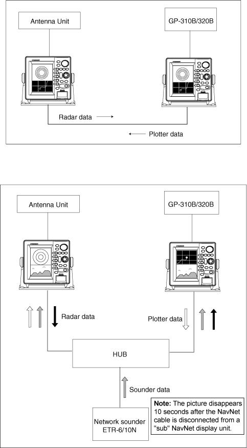
All NavNet products incorporate a “network circuit board” to integrate each NavNet product on board through an optional LAN cable (Ethernet 10BASE-T). Each NavNet product is assigned an IP address to enable transfer of images between other NavNet products. For example, video plotter pictures can be transferred to a radar and vice versa. Pictures received via the NavNet may be adjusted at the receiving end.
A NavNet system may consist of up to four display units and one ETR. For a system incorporating three or more products, a “hub” is required to process data.
NavNet system
NavNet system
x
SYSTEM CONFIGURATIONS
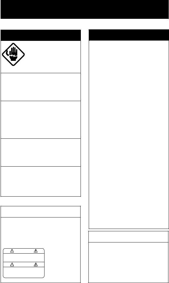
Two-unit NavNet system
Two-unit NavNet system
Three-or more unit NavNet system (Max. 4 NavNet capable display units)
Three-or more unit NavNet system
xi
This page is intentionally left blank.

1.OPERATIONAL OVERVIEW
This chapter provides basic information needed to get you started using your radar. The follow topics are presented:
•Control overview
•Chart card insertion
•Power on/off
•Contrast, brilliance and hue (Color series only) adjustments
•Display selection
•Data boxes
•Function keys
•Simulation display
NOTICE
The brilliance of the LCD is adjustable to match a wide variety of lighting conditions. However, its maximum setting may not be sufficiently bright to permit viewing of the display with polarized sunglasses.
Note: The example screens shown in this manual may not match the screens you see on your display. The screen you see depends on your system configuration and equipment settings.
1-1
1. OPERATIONAL OVERVIEW
1.1Operating Controls
1.1.1Display unit controls
Overview of display unit controls
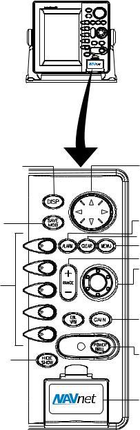
The radar systems are mainly operated with controls of the display unit (and remote controller). Ten keys are labeled and they provide the function shown on their labels. The five soft keys provide various functions according to current operating mode. The [ENTER] knob mainly functions to register selections on the menu and enter alphanumeric data. The cursor pad’s main function is to move the cursor across the screen. Whenever you operate a key, a single beep confirms operation. Invalid operation causes the unit to emit three beeps.
Selects display mode.
Momentary press:
Registers own ship’s position as a waypoint.
Press three seconds:
Marks man overboard position.
Soft keys
Shows or hides the soft keys, function keys, nav data alternately.
Cursor pad
Selects menu items and options; shifts cursor. Press, release and press again to change setting consecutively.
Opens/closes the alarm menu.
 Clears data; erases selected mark.
Opens/closes the main menu.
Selects a range. ENTER knob
Push: Registers options on menus.
Rotate: Selects character; adjusts sensitivity (sounder, radar); chooses menu items and options.
 Displays the soft keys for EBL/VRM.
Radar: Displays the soft keys for adjustment of gain, A/C SEA, A/C RAIN and FTC.
Sounder: Adjusts gain.
Long press: Turns power on/off.
Momentary press: Opens the display for adjustment of brilliance, etc. For radar, switches STBY and TX.
Chart slot
Control panel
1-2
1. OPERATIONAL OVERVIEW
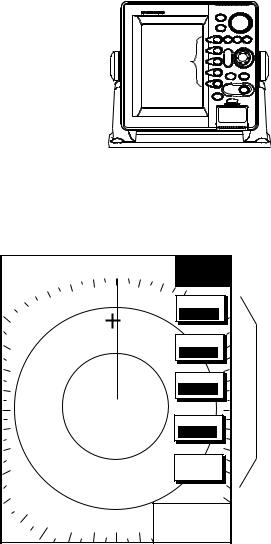
Soft keys
The five soft keys’ functions change according to the operation. Their labels for their current functions are shown on the screen to the left of the keys. To hide or show the soft keys, press the [HIDE/SHOW] key. Each press of the key shows preset soft keys, user function keys or turns off navigation information (at the top of the screen).
SOFT
KEYS
Display unit
Some soft keys show the current state of the soft key function in reverse video as shown below.
.250/ |
.125nm |
° M |
SIGNAL |
|
319.9 |
PROCESS |
|
SP |
|
|
|
H-UP |
|
|
|
|
|
|
I. REJ |
|
|
|
LOW |
E. AVG*
OFF
PULSE |
SHORT |
E. STR
LOW
RETURN |
+359.9° R
0.24nm
Current option shown in reverse video
*: Only when MODEL 1833/C series are used as radar source.
Plotter display
1-3

1. OPERATIONAL OVERVIEW
[ENTER] knob
The [ENTER] knob functions to
•Register data
•Enter alphanumeric data such as waypoint name
•Select menu items and options
•Adjust setting
Clockwise rotation of the knob selects an alphabet, symbol or numeric, in one of the sequences shown below. After you have selected desired alphanumeric character push the [ENTER] knob to register your selection.
[ENTER] knob
ENTER knob
Alphabet, symbol, numeric
A ! B ! C ! D ! E ! F ! G ! H ! I ! J ! K ! L ! M ! N ! O ! P ! Q ! R ! S ! T ! U ! V ! W ! X ! Y ! Z ! & ! _ ! ’ ! # ! 0 ! 1 ! 2 ! 3 ! 4 ! 5 ! 6 ! 7 ! 8 ! 9
Numerics
0 ! 1 ! 2 ! 3 ! 4 ! 5 ! 6 ! 7 ! 8 ! 9
1-4
1. OPERATIONAL OVERVIEW
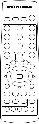
1.1.2Remote controller
Operating distance 90° : Up to 5 m
SAVE ± 45° : Up to 3 m
|
RANGE |
|
DISP |
MOB |
|
ABC |
1 |
DEF |
2 |
GHI |
3 |
JKL |
4 |
MNO |
5 |
PQR |
6 |
STU |
7 |
VWX |
8 |
YZ& |
9 |
EBL/VRM |
’# 0 |
GAIN |
|||
WPT |
|
|
CENTER |
||
MARK |
|
|
|
|
CNTL |
ENT |
|
|
|
|
|
ENT
Replace the batteries (AA) when the distance from which the display unit can be operated shortens.
Note: The remote controller may become damaged if dropped. Mishandling of the remote controller is not covered by
the warranty.
|
|
CLEAR |
MENU |
|
|
|
||
|
BRILL |
TONE |
TX/STBY |
ACQ |
|
|
|
|
|
|
|
ALARM |
HIDE/SHOW |
|
|
|
|
|
SK1 |
SK2 |
SK3 SK4 |
SK5 |
|
|
|
|
|
|
|
|
|
|
Remote controller |
|
|
|
|
|
|
|
|
|
|
|
Key |
Function |
|
|
|
|
Key |
|
Function |
|
|
|
|
|
|
|
||
RANGE |
Same as RANGE key on |
|
|
CLEAR |
|
Same as CLEAR key on |
||
|
display unit. |
|
|
|
|
|
|
display unit. |
|
|
|
|
|
|
|
||
DISP |
Same as DISP key on |
|
|
MENU |
|
Same as MENU key on |
||
|
display unit. |
|
|
|
|
|
|
display unit. |
|
|
|
|
|
|
|||
SAVE MOB |
Same as SAVE MOB key on |
|
BRILL |
|
Adjusts display brilliance. |
|||
|
display unit. |
|
|
|
|
|
|
|
|
|
|
|
|
|
|
|
|
Ten keys |
Enter alphanumerics. |
|
|
|
TONE |
|
Adjusts display contrast. |
|
|
|
|
|
|
|
|
||
EBL/VRM |
Same as EBL/VRM key on |
|
|
TX/STBY |
|
Toggles radar between |
||
|
display unit. |
|
|
|
|
|
|
standby and transmit. |
|
|
|
|
|
|
|
||
GAIN |
Same as GAIN key on |
|
|
ACQ |
|
Acquires radar target. |
||
|
display unit. |
|
|
|
|
|
|
(Requires radar source |
|
|
|
|
|
|
|
|
equipped with ARP.) |
|
|
|
|
|
|
|||
WPT |
Displays “alphabet” WPT list |
|
ALARM |
|
Same as ALARM key on the |
|||
|
on plotter display. |
|
|
|
|
|
display unit. |
|
|
|
|
|
|
|
|||
MARK ENT |
Same as MARK ENTRY soft |
|
HIDE/SHOW |
|
Same as HIDE/SHOW key |
|||
|
key. |
|
|
|
|
|
|
on display unit. |
|
|
|
|
|
|
|||
CENTER |
Returns own ship to screen |
|
SK1 – SK5 |
|
Same as soft keys on |
|||
|
center on plotter display. |
|
|
(soft keys) |
|
display unit. |
||
|
|
|
|
|
|
|
||
CNTL |
Switches control between |
|
|
ENT |
|
Same as ENTER knob on |
||
|
displays on combination |
|
|
|
|
display unit. |
||
|
displays. |
|
|
|
|
|
|
|
|
|
|
|
|
|
|
|
|
1-5
1. OPERATIONAL OVERVIEW
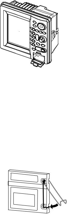
1.2Inserting a Chart Card
Your unit reads FURUNO and Nav-Charts™ (NAVIONICS), or C-MAP chart cards, depending on its specifications. Insert the appropriate chart card for your area as follows:
1. Open the chart card slot lid.
 Chart slot
Display unit
2.Insert desired chart card groove side up.
3.Close the lid to protect the chart drive.
Note 1: Do not insert or remove the chart card while turning power on. This may cause the equipment to freeze.
Note 2: Do not remove a card while the chart is being drawn. This may cause the equipment to freeze.
Note 3: A card remover is supplied to ease removal of chart cards. Attach the card remover to the right-hand side hole on the card and pull to remove card. You can leave the card remover attached to the card while the card is in the card slot - push the card remover leftward until it contacts the recessed area in the card.
Note 4: For multiple display units, do not use the same chart card type in more than one display unit.
Chart card and card remover
1-6
1. OPERATIONAL OVERVIEW
1.3Turning the Unit On/Off
Press the [POWER/BRILL] key to turn the unit on. A beep sounds and the equipment proceeds in the sequence shown below, displaying the product information screen, startup test results and the chart usage disclaimer, in that order. The startup test checks the ROM, RAM, internal battery and backup data for proper operation, displaying the results for each as OK or NG (No Good). If NG appears, an appropriate message appears on the screen. For any NG, try to press any key to go to the chart disclaimer screen, then perform the diagnostic test referring to the paragraph “7.6 Diagnostics.”
Chart List
Host Name
RADAR PLOTTER
STATION NAME: RADAR 
FURUNO ELECTRIC CO., LTD. CHARTS AVAILABLE FLYBRDG = ANB01004
RADAR = ANB01003
Product information
STARTUP TEST
ROM |
OK |
|
|
RAM |
OK |
|
|
BACKUP DATA |
OK |
|
|
INTERNAL BATTERY |
OK |
Startup test
** = Program version no.
(Two program version numbers. One for NAVIO and one for C-MAP.)
NO NATIONAL HYDROGRAPHIC OFFICE HAS VERIFIED THE INFORMATION IN THIS
COASTLINE DATA CARD AND NONE ACCEPT LIABILITY FOR THE ACCURACY OF REPRODUCTION OR ANY MODIFICATIONS MADE THEREAFTER. THIS PRODUCT WITH THIS COASTLINE DATA CARD DOES NOT REPLACE THE REQUIREMENT TO USE THE APPROPRIATE PRODUCTS FOR NAVIGATION ACCORDING TO NATIONAL AND INTERNATIONAL REGULATIONS.
PROGRAM No. 03591730**
Chart disclaimer
The magnetron in the antenna unit takes about one minutes and thirty seconds to warm up before the radar can be operated. The time remaining for warm up of the magnetron appears at the center of the display, counting down from 1:30 to 0:01.
You may press any key at the chart disclaimer screen to show the last-used display, or wait several seconds to let the equipment do it for you.
To turn the unit off, press and hold down the [POWER/BRILL] key until the screen goes dark (approx. 3 sec.). To protect the LCD attach the hard cover. Note that the network sounder will be turned off approx. three minutes after turning off the power.
Note: You are asked if you want to start the simulation mode, which provides simulated operation of the equipment, the first time you turn on the power (or any time power is applied after a memory reset) the message shown below is displayed. Push the [ENTER] knob to start the simulation mode, or press the [CLEAR] key to start normal operation. For further details about the simulation mode, see the paragraph “1.9 Simulation Display.”
START
SIMULATION MODE?
YES ... PUSH ENTER KNOB
NO ... PUSH CLEAR KEY
TO SKIP.
1-7
1. OPERATIONAL OVERVIEW
1.4Cursor Pad, Cursor
The cursor pad mainly functions to shift the cursor, for measurement of range and bearing to a location (radar) and latitude and longitude position (plotter). Operate the cursor pad to shift the cursor. The cursor moves in the direction of the arrow or diagonal pressed, on the cursor pad.
For the plotter display, the cursor can be turned off with the CENTER soft key. This also returns own ship marker to the screen center.
|
.250/ |
.125nm |
319.9 |
° M |
|
SP |
|
|
|
Cursor |
H-UP |
|
|
|
|
|
|
SIGNAL |
|
|
|
|
|
|
|
|
|
|
PROC |
RADAR |
DISPLY |
NAV |
FUNC |
TARGET |
ZOOM &
D. BOX
+359.9° R
0.24nm
Radar display
Cursor data |
+ |
34° 22. 3456'N |
272.4° M |
TRIP NU |
080° 22. 3456'E |
15.9 nm |
99.9 nm |
||
L/L position, |
|
|
|
|
Range and |
16.0nm |
|
MARK |
|
bearing from |
|
|
|
ENTRY |
own ship to |
|
|
|
MODE |
cursor |
|
|
|
|
|
|
|
NTH UP |
|
|
|
|
|
CENTER |
Cursor |
|
|
|
|
GOTO |
CURSOR |
D. BOX
ON/ OFF
Plotter display
Cursor, cursor data
1-8
1. OPERATIONAL OVERVIEW
1.5Display Brilliance, Panel Brilliance, Contrast, Hue
You can adjust display brilliance, panel brilliance, contrast and hue (MODEL1722C series only) as shown below.
1.5.1Display brilliance, panel brilliance
1.Press the [POWER/BRILL] key momentarily. A set of soft keys for adjustment of brilliance, contrast and hue (MODEL1722C series only) appear. The last-used adjustment window appears. In the example below the display
brilliance adjustment window is shown.
Current selection is higtlighted.
.250/ |
.125nm |
319.9 |
° M |
BRILL |
SP |
|
|
CONTST |
|
H-UP |
|
|
|
|
|
|
|
|
|
DISPLY |
BRILL |
PANEL |
BRILL |
CONTST |
/HUE |
RADAR |
STBY |
RETURN |
DISPLAY BRILLIANCE
 8
8
.250/ |
.125nm |
° M |
BRILL |
|
319.9 |
|
|
SP |
|
CONTST |
|
H-UP |
|
|
|
|
|
|
|
DISPLY |
BRILL |
PANEL |
BRILL |
CONTST |
RADAR |
STBY |
RETURN |
DISPLAY BRILLIANCE
 8
8
MODEL1722C series |
MODEL1722 series |
Brilliance adjustment soft keys
2.Press the DISPLY BRILL or PANEL BRILL soft key as appropriate. An adjustment window appears at the bottom of the screen. This window shows the name of the item selected for adjustment plus current brilliance level, by bar graph.
DISPLAY BRILLIANCE
 8
8
Display brilliance
PANEL BRILLIANCE
 8
8
Panel brilliance
Display brilliance and panel brilliance windows
3.Adjust the [ENTER] knob, clockwise to raise the setting or counterclockwise to decrease it. You may also use the soft key pressed at step 2, in which case the item selected is adjusted cyclically, from low to high. Eight levels of display brilliance and panel brilliance are available.
4.Hit the RETURN soft key to finish.
The display brilliance can be adjusted by pressing the [POWER/BRILL] key. If the unit is turned on with minimum display brilliance, press the [POWER/BRILL] key consecutively to adjust the brilliance.
1-9

1. OPERATIONAL OVERVIEW
1.5.2Contrast
1.Press the [POWER/BRILL] key momentarily.
2.Press the CONTST (monochrome) or CONTST/HUE (color) soft key.
3.For MODEL1722C series, two soft keys appear at the pressing of the CONTST/HUE soft key: CONTST and HUE. Press the CONTST soft key to adjust the contrast.
CONTRAST
8
Contrast window
4.Adjust the [ENTER] knob, clockwise to raise the setting or counterclockwise to decrease it. You may also use the CONTST soft key, in which case the item selected is adjusted cyclically, from low to high. 16 levels (monochrome) and 10 levels (color) of contrast are available.
5.Press the RETURN soft key to finish.
1.5.3Hue (MODEL1722C series)
1.Press the [POWER/BRILL] key momentary.
2.Press the CONTST/HUE soft key.
3.Press the HUE soft key to show the hue setting window.
HUE
▲
¡DAY
¡NIGHT
¡TWILIGHT
¤ MANUAL SET
▼
Hue window
4.Operate the cursor pad or [ENTER] knob to select hue desired, referring to the table below. MANUAL SET follows the color settings on the RADAR DISPLAY SETUP for the radar, CHART DETAILS menu for the plotter and SOUNDER MENU for the sounder.
|
Day |
Night |
Twilight |
Applicable mode |
Characters |
Black |
Red |
Green |
Plotter, radar, sounder |
Radar ring |
Green* |
Red |
Green* |
Radar |
Radar echo |
Orange |
Red |
Yellow |
Radar |
Background |
White |
Black |
Blue |
Plotter, radar |
Landmass |
Yellow |
Light Yellow |
Dim Yellow |
Radar |
|
|
|
|
*: Red on C-map |
5. Hit the RETURN soft key to finish.
Note: When using the overlay screen, the own ship track will be hidden if the radar background and own ship track are blue and the “MANUAL” hue setting is used. In this case, set HUE to other position and then return to “MANUAL” to show the own ship track in black.
1-10
1. OPERATIONAL OVERVIEW
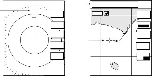
1.6Selecting a Display
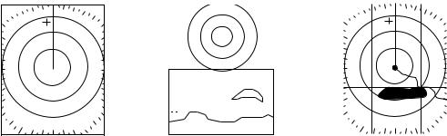
1.6.1Display modes
If you have a navigator and network sounder connected, four full-screen displays are available: radar, plotter, and video sounder and navigation data. (MODEL1722C series have five screens, those mentioned above plus the overlay screen.) In addition to the full-screen display, you can divide the screen into half-screen combination displays to show two sets of images (data).
Full screen |
|
|
|
|
|
|
|
|
|
|
|
|
|
|
|
|
|
|
|
|
|
|
|
|
|
|
|
|
|
|
|
|
|
|
|
|
|
|
|
|
|
|
|
|
|
|
|
|
|
|
|
|
|
|
|
|
|
|
|
|
|
|
|
|
|
|
|
|
|
|
|
|
|
|
|
|
|
|
|
|
|
|
|
|
|
|
|
|
|
|
|
|
|
|
|
|
|
|
|
|
|
|
|
|
|
|
|
|
|
|
|
|
|
|
|
|
|
|
|
|
|
|
|
|
|
|
|
|
|
|
|
Combination screen |
Overlay screen |
||||||||||
(Ex. radar) |
(Ex. radar + sounder) |
(Radar and plotter, |
|||||||||
|
|
|
|
|
|
|
|
|
|
|
color model only. |
|
|
|
|
|
|
|
|
|
|
|
Requires L/L data) |
Display screens
The table below shows the displays available with each screen type.
Screen type and available display screen
Full screen |
Combination screen |
Overlay screen options |
|
options |
(Color series only) |
|
|
|
Radar, plotter, sounder, |
Radar, plotter, echo |
Radar + plotter |
nav data |
sounder, compass, |
|
|
highway, |
|
|
compass/highway, nav |
|
|
data, overlay |
|
|
|
|
1-11

1. OPERATIONAL OVERVIEW
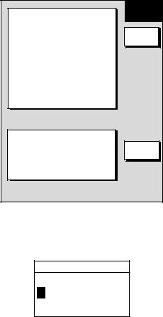
1.6.2Selecting a display
1.Press the [DISP] key to show the full-screen selection window. The icons of modes not available are marked with “X” mark. PAGE1-PAGE5 are user-arrangeable displays called “hot pages,” which you can configure as you like. For further details, see “5.5 Hot Page Setup.”
RADAR |
PLOT |
SNDR |
NAV |
OVRLY |
PAGE1 |
PAGE2 |
PAGE3 |
PAGE4 |
PAGE5 |
·TURN KNOB TO SELECT MODE AND PUSH KNOB TO ENTER.
·PUSH ANY SOFT KEY TO SELECT IMAGE SOURCE.
Basic display screens
Hot pages
Full-screen selection window (“overlay” for color model)
2.Rotate the [ENTER] knob to select a basic display screen or a hot page screen.
3.Push the [ENTER] knob. If you selected a basic display screen, a set of combination display screens corresponding to the basic display screen that was selected appear. In the example below, radar combination displays are shown.
PUSH ENTER KNOB. |
Radar combination screen selection window
4.Operate the [ENTER] knob to select the combination screen display desired and push it to set.
1-12
1. OPERATIONAL OVERVIEW
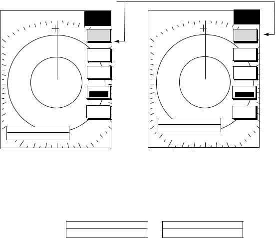
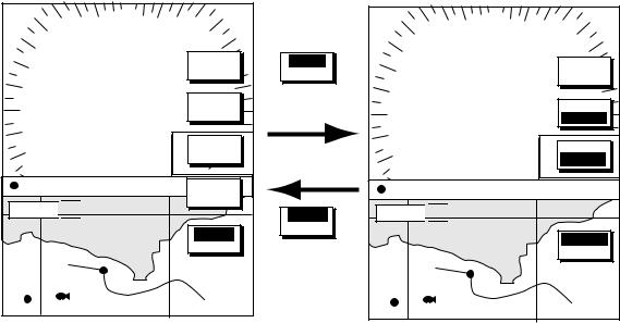
1.6.3Switching control in combination and overlay screens
A soft key is provided in relevant combination and overlay screens (color series only) to switch control between displays. In the example below, the RADAR CNTRL and PLOTTR CNTRL soft keys enable switching control between the radar and plotter screens in the plotter/radar combination display.
12 3nm LP
H-UP
SIGNAL |
PROC. |
ST-BY |
RADAR |
|
DISPLY |
359NAV.9° R
+ FUNC
11.7nm
34° 22. |
3456'N |
359.9° M |
TRIP NU |
080° 22. |
3456'E |
19.9 kt |
TARGET99.9 nm |
16.0nm 


RADAR |
CNTRL |
WP-002 FISH
Radar display selected
CNTLRADAR
RADARCNTRL
To adjust plotter
PLOTTR |
CNTRL |
To adjust radar
12 3nm LP
H-UP
MARK |
ENTRY |
ST-BY
MODE
NTH UP
359NAV.9° R
+ POS
11.7nm
34° 22. |
3456'N |
359.9° M |
TRIP NU |
080° 22. |
3456'E |
19.9 kt |
99.9 nm |
16.0nm 


PLOTTR
CCNTRL
WP-002 FISH
Plotter display selected
How to switch control between modes in the plotter/radar combination display
1-13
1. OPERATIONAL OVERVIEW
1.6.4Selecting radar source
When other network radar is connected to the equipment, you may select an image source as shown below. This is not necessary when no other network radar is connected. Select one host name for the source though there are two or three radar units on the net.
Note: Turn the power off whenever changing the source.
1.Press the [DISP] key.
2.Press any soft key to show the following display.
▲
RADAR SOURCE
RADAR - - -
SOUNDER SOURCE* SOUNDER-
IP ADDRESS 172.031.003.001
HOST NAME RADAR - - -
SELECT SOURCE
EDIT |
IF THERE IS MORE THAN ONE NETWORK RADAR OR ECHO SOUNDER, YOU MAY SELECT THE IMAGE SOURCES FOR DISPLAY.
RETURN |
*: Do not change this setting.
Select source menu
3. Use the cursor pad to select RADAR SOURCE and press the EDIT key.
RADAR SOURCE
RADAR - - -
Radar source
Radar source and sounder source windows
4.Use the cursor pad and [ENTER] knob to enter source host name: ◄ or ► to select position and rotate the [ENTER] knob to select character.
5.Press the [ENTER] soft key or [ENTER] knob.
6.Confirm that the correct host name is entered.
7.Press the [DISP] key to finish.
8.Turn the power off and on again.
Note: Sources names are determined at installation. For example, the source names for radars in a two radar system might be “RADAR” and “RADAR1”.
1-14
1. OPERATIONAL OVERVIEW
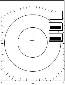
1.7Data Boxes
Data boxes, providing navigation data, may be shown on any full-screen display. Up to six data boxes (two in case of large characters) may be shown, and the default data boxes are position (in latitude and longitude), course over ground, speed over ground, trip log and cursor position. The user may choose which data to display, where to locate it, and show or hide it as desired. In addition, data boxes may be set independently for each display mode (radar, plotter, sounder). For how to select data for the data boxes, see paragraph “5.5 Data Boxes Setup”.
.125nm
.250/SP
H-UP
319.9° M
MARK |
ENTRY |
MODE
NTH UP
NAV |
POS |
TRIP LOG |
|
|
|
|
|
|
D.BOX |
|
|
177nm |
|
|
|
|
|
|
ON |
/OFF |
|
|
|
|
|
|
|
|
|
||
POSITION |
COG |
|
SOG |
|
|||||
47° |
|
|
|||||||
58.535'N |
323.6° M |
|
|
|
20.0 kt |
|
|||
36.496'W |
|
|
|
|
|||||
122° |
|
|
|
|
|
|
|
|
|
|
|
|
|
|
|
|
350.4° M |
|
|
|
|
|
|
|
|
|
0.000 nm |
|
|
|
|
|
|
|
|
|
|
||
|
|
|
|
|
|
|
|
|
|
Data boxes
Plotter display, showing data boxes
1.7.1Showing, hiding data boxes with soft key
Radar: ZOOM & D. BOX → D. BOX ON/OFF (EBL/VRM data box, cursor data box also shown/hidden)
Plotter: D. BOX ON/OFF
Sounder: AUTO/D. BOX→ D. BOX ON/OFF
1.7.2Rearranging data boxes
You may select the location for data boxes as follows:
1.Using the cursor pad, move the cursor to the data box you wish to move. As the cursor enters the box it changes to a hand. Push the [ENTER] knob, and the hand changes to a fist, meaning the box is correctly selected.
2.Use the cursor pad to drag the data box to the location desired and push the [ENTER] knob.
1.7.3Temporarily erasing a data box
You may temporarily erase a data box. Use the cursor pad to place the cursor inside the data box you wish to erase and press the [CLEAR] key. To redisplay the box, press the ZOOM & D.BOX soft key D.BOX soft key to display it.
1-15

1. OPERATIONAL OVERVIEW
1.8Function Keys
The function keys provide for one-touch call up of a desired function. The default function key settings are as shown in the table below.
Function |
Default Setting, Key Label |
|
||
Key |
|
|
|
|
Radar |
Plotter |
Echosounder |
||
|
||||
|
|
|
|
|
#1 |
Heading line on/off, |
Track on/off, TRK |
TLL output, TLL |
|
|
HL |
|
|
|
|
|
|
|
|
#2 |
Rings on/off, RNG |
Edit mark/line, EML |
Clutter, CLT |
|
|
|
|
|
|
#3 |
Echo trail, TRL |
Ruler, RUL |
Signal level, SLV |
|
|
|
|
|
|
#4 |
Offcenter, SFT |
Add new waypoint, |
Noise limiter, NL |
|
|
|
ADD |
|
|
|
|
|
|
|
#5 |
Radar source, RSR |
Waypoint |
Picture advance, PA |
|
|
|
alphanumeric list, |
|
|
|
|
ALP |
|
|
|
|
|
|
|
1.8.1Executing a function
1.Press the [HIDE/SHOW] key to replace the preset soft key labels with the function key labels.
.250/ |
.125nm |
319.9 |
° M |
34° |
22. |
3456'N |
359.9° M |
TRIP NU |
|
|
TARGET |
080 |
° |
22. |
3456'E |
19.9 kt |
99.9 nm |
||
SP |
|
|
|
|
|
|
|
||
H-UP |
|
|
|
16.0nm |
|
|
|
||
|
|
|
|
|
|
|
|||
H |
T |
|
R |
||
L |
||
K |
||
|
R |
|
|
E |
|
N |
|
|
M |
|
G |
|
|
L |
|
T |
Function |
|
R |
Function |
R |
|
U |
||
L |
keys |
|
L |
keys |
S |
|
|
||
|
|
A |
|
|
F |
|
|
D |
|
T |
002WP |
FISH |
D |
|
|
|
|
|
|
R |
|
|
BRIDGE |
|
|
|
A |
|
|
S |
|
|
L |
|
R |
|
|
p |
|
+359.9° R |
|
|
|
|
0.24nm |
|
|
|
|
Radar |
|
|
Plotter |
|
Function keys
2. Press function key desired.
Note: Function keys can be individually programmed for the radar, plotter and sounder displays. For further details see the following:
Radar: paragraph 5.2.3 Plotter: paragraph 5.3.2 Sounder: paragraph 5.9.4
1-16
Loading...