


TX200 S6
Table of contents
 Loading...
Operating Manual - English
PRIMERGY TX200 S6
Server
Operating Manual
Edition July 2010

Comments… Suggestions… Corrections…
The User Documentation Department would like to
know your opinion of this manual. Your feedback helps
us optimize our documentation to suit your individual
needs.
Feel free to send us your comments by e-mail to email:
manuals@ts.fujitsu.com.
Certified documentation
according to DIN EN ISO 9001:2000
To ensure a consistently high quality standard and
user-friendliness, this documentation was created to
meet the regulations of a quality management system
which complies with the requirements of the standard
DIN EN ISO 9001:2000.
cognitas. Gesellschaft für Technik-Dokumentation mbH
www.cognitas.de
Copyright and Trademarks
Copyright © 2010 Fujitsu Technology Solutions GmbH.
All rights reserved.
Delivery subject to availability; right of technical modifications reserved.
All hardware and software names used are trademarks of their respective manufacturers.
– The contents of this manual may be revised without prior notice.
– Fujitsu assumes no liability for damages to third party copyrights or other rights arising from
the use of any information in this manual.
– No part of this manual may be reproduced in any without the prior written permission of
Fujitsu.
Microsoft, Windows, Windows Server, and Hyper V are trademarks or registered trademarks of
Microsoft Corporation in the USA and other countries.
Intel and Xeon are trademarks or registered trademarks of Intel Corporation or its subsidiaries
in the USA and other countries.

Before reading this manual
For your safety
This manual contains important information for safely and correctly using this
product.
Carefully read the manual before using this product. Pay particular attention to
the accompanying manual "Safety notes and other important information" and
ensure these safety notes are understood before using the product. Keep this
manual and the manual "Safety notes and other important information" in a safe
place for easy reference while using this product.
Radio interference
This product is a "Class A" ITE (Information Technology Equipment). In a
domestic environment this product may cause radio interference, in which case
the user may be required to take appropriate measures. VCCI-A
Aluminum electrolytic capacitors
The aluminum electrolytic capacitors used in the product's printed circuit board
assemblies and in the mouse and keyboard are limited-life components. Use of
these components beyond their operating life may result in electrolyte leakage
or depletion, potentially causing emission of foul odor or smoke.
As a guideline, in a normal office environment (25°C) operating life is not
expected to be reached within the maintenance support period (5 years).
However, operating life may be reached more quickly if, for example, the product
is used in a hot environment. The customer shall bear the cost of replacing
replaceable components which have exceeded their operating life. Note that
these are only guidelines, and do not constitute a guarantee of trouble-free
operation during the maintenance support period.
High safety use
This product has been designed and manufactured for general uses such as
general office use, personal use, domestic use and normal industrial use. It has
not been designed or manufactured for uses which demand an extremely high
level of safety and carry a direct and serious risk to life or body if such safety
cannot be ensured.
TX200 S6 Operating Manual

These uses include control of nuclear reactions in nuclear power plants,
automatic airplane flight control, air traffic control, traffic control in mass
transport systems, medical devices for life support, and missile guidance control
in weapons systems (hereafter, "high safety use"). Customers should not use
this product for high safety use unless measures are in place for ensuring the
level of safety demanded of such use. Please consult the sales staff of Fujitsu if
intending to use this product for high safety use.
Measures against momentary voltage drop
This product may be affected by a momentary voltage drop in the power supply
caused by lightning. To prevent a momentary voltage drop, use of an AC
uninterruptible power supply is recommended.
(This notice follows the guidelines of Voltage Dip Immunity of Personal
Computer issued by JEITA, the Japan Electronics and Information Technology
Industries Association.)
Technology controlled by the Foreign Exchange and Foreign Trade
Control Law of Japan
Documents produced by Fujitsu may contain technology controlled by the
Foreign Exchange and Foreign Trade Control Law of Japan. Documents which
contain such technology should not be exported from Japan or transferred to
non-residents of Japan without first obtaining authorization in accordance with
the above law.
Harmonic Current Standards
This product conforms to harmonic current standard JIS C 61000-3-2.
Only for the Japanese market:
About SATA hard disk drives
The SATA version of this server supports hard disk drives with SATA / BC-SATA
storage interfaces. Please note that the usage and operation conditions differ
depending on the type of hard disk drive used.
Please refer to the following internet address for further information on the
usage and operation conditions of each available type of hard disk drive:
http://primeserver.fujitsu.com/primergy/harddisk/
Operating Manual TX200 S6

Only for the Japanese market:
I Although described in this manual, some sections do not apply to the
Japanese market. These options and routines include:
– USB Flash Module (UFM)
– CSS (Customer Self Service)
TX200 S6 Operating Manual

Operating Manual TX200 S6

Contents
1 Preface . . . . . . . . . . . . . . . . . . . . . . . . . . . . . 11
1.1 Concept and target groups for this manual . . . . . . . . . 12
1.2 Documentation overview . . . . . . . . . . . . . . . . . . . 12
1.3 Features . . . . . . . . . . . . . . . . . . . . . . . . . . . . . 14
1.4 Notational conventions . . . . . . . . . . . . . . . . . . . . 25
1.5 Technical data . . . . . . . . . . . . . . . . . . . . . . . . . 26
2 Installation steps, overview . . . . . . . . . . . . . . . . . . 29
3 Important information . . . . . . . . . . . . . . . . . . . . . 31
3.1 Safety instructions . . . . . . . . . . . . . . . . . . . . . . . 31
3.2 ENERGY STAR . . . . . . . . . . . . . . . . . . . . . . . . . 39
3.3 CE conformity . . . . . . . . . . . . . . . . . . . . . . . . . 40
3.4 FCC Class A Compliance Statement . . . . . . . . . . . . . 40
3.5 Transporting the server . . . . . . . . . . . . . . . . . . . . 41
3.6 Notes on installing the server in the rack . . . . . . . . . . 42
3.7 Environmental protection . . . . . . . . . . . . . . . . . . . 43
4 Hardware installation . . . . . . . . . . . . . . . . . . . . . . 45
4.1 Unpacking the server . . . . . . . . . . . . . . . . . . . . . 46
4.2 Setting up the floorstand model . . . . . . . . . . . . . . . . 47
4.2.1 Mounting the anti-tilt bracket . . . . . . . . . . . . . . . . . . . 48
4.3 Installing/removing the rack model . . . . . . . . . . . . . . 49
4.3.1 Rack system requirements . . . . . . . . . . . . . . . . . . . 49
4.3.2 Installation in PRIMECENTER/DataCenter/
19-inch standard rack . . . . . . . . . . . . . . . . . . . . . . 52
4.3.3 Installation in 3rd party racks . . . . . . . . . . . . . . . . . . 57
TX200 S6 Operating Manual

Contents
4.4 Connecting devices to the server . . . . . . . . . . . . . . . 59
4.5 Connecting the server to the mains . . . . . . . . . . . . . . 60
4.5.1 Using cable ties . . . . . . . . . . . . . . . . . . . . . . . . . . 62
4.6 Notes on connecting/disconnecting cables . . . . . . . . . . 63
5 Starting up and operation . . . . . . . . . . . . . . . . . . . . 65
5.1 Access to the drives (floorstand model) . . . . . . . . . . . . 65
5.1.1 Access to the accessible drives . . . . . . . . . . . . . . . . . . 65
5.1.2 Access to the HDD modules . . . . . . . . . . . . . . . . . . . 67
5.2 Control elements and indicators . . . . . . . . . . . . . . . . 68
5.2.1 Front of server . . . . . . . . . . . . . . . . . . . . . . . . . . 68
5.2.1.1 ID card . . . . . . . . . . . . . . . . . . . . . . . . . . . . . 69
5.2.1.2 Control elements . . . . . . . . . . . . . . . . . . . . . . . 69
5.2.1.3 LEDs on the control panel . . . . . . . . . . . . . . . . . . . 70
5.2.1.4 Indicators on the drives . . . . . . . . . . . . . . . . . . . . 71
5.2.2 Rear of server . . . . . . . . . . . . . . . . . . . . . . . . . . . 73
5.2.2.1 Indicators on the connector panel . . . . . . . . . . . . . . . 73
5.2.2.2 Indicators on the hot-plug power supply unit . . . . . . . . . 76
5.3 Switching the server on and off . . . . . . . . . . . . . . . . 77
5.4 Configuring the server . . . . . . . . . . . . . . . . . . . . . 79
5.4.1 Configuring the onboard SATA controller . . . . . . . . . . . . . 79
5.4.2 Configuring the SAS/SATA RAID controller . . . . . . . . . . . . 79
5.4.3 Configuring the server and installing the operating system
with the ServerView Installation Manager . . . . . . . . . . . . 80
5.4.4 Configuring the server and installing the operating system
without the ServerView Installation Manager . . . . . . . . . . . 81
5.5 Cleaning the server . . . . . . . . . . . . . . . . . . . . . . . 82
6 Property and data protection . . . . . . . . . . . . . . . . . . 83
6.1 BIOS Setup security functions . . . . . . . . . . . . . . . . . 83
7 Troubleshooting and tips . . . . . . . . . . . . . . . . . . . . 85
7.1 Power-on indicator remains unlit . . . . . . . . . . . . . . . . 85
7.2 Server switches itself off . . . . . . . . . . . . . . . . . . . . 86
Operating Manual TX200 S6

Contents
7.3 Screen remains blank . . . . . . . . . . . . . . . . . . . . . 86
7.4 Flickering stripes on monitor screen . . . . . . . . . . . . . 87
7.5 No screen display or display drifts . . . . . . . . . . . . . . 87
7.6 Incorrect date and time . . . . . . . . . . . . . . . . . . . . 88
7.7 Drives reported as "dead" when starting system . . . . . . 88
7.8 Added drive reported as defective . . . . . . . . . . . . . . 89
7.9 Error message on screen . . . . . . . . . . . . . . . . . . . 89
8 CSS components . . . . . . . . . . . . . . . . . . . . . . . . 91
8.1 Hot-plug components . . . . . . . . . . . . . . . . . . . . . 92
8.1.1 Hot-plug power supply units (optional) . . . . . . . . . . . . . . 92
8.1.1.1 Replacing the hot-plug power supply unit . . . . . . . . . . 92
8.1.2 Hot-plug hard disk drives . . . . . . . . . . . . . . . . . . . . 93
8.1.2.1 3.5-inch HDD module and dummy module . . . . . . . . . . 95
8.1.2.2 2.5-inch HDD module and dummy module . . . . . . . . . . 96
8.1.2.3 Handling hard disk drives and HDD modules . . . . . . . . 97
8.1.2.4 Floorstand: removing the hard disk cover . . . . . . . . . . 98
8.1.2.5 Removing/installing the dummy module . . . . . . . . . . . 99
8.1.2.6 Installing the HDD module . . . . . . . . . . . . . . . . . . 100
8.1.2.7 Removing the HDD module . . . . . . . . . . . . . . . . . 102
8.2 Non-hot-plug components . . . . . . . . . . . . . . . . . . . 103
8.2.1 Opening the server and identifying the defective
CSS component . . . . . . . . . . . . . . . . . . . . . . . . . 104
8.2.1.1 Opening the server . . . . . . . . . . . . . . . . . . . . . . 104
8.2.1.2 Removing system fan 2 (and 4) . . . . . . . . . . . . . . . 105
8.2.1.3 Removing system fan 1 (and 3) . . . . . . . . . . . . . . . 106
8.2.1.4 Identifying a CSS component . . . . . . . . . . . . . . . . 107
8.2.2 Replacing a memory module . . . . . . . . . . . . . . . . . . 108
8.2.2.1 Removing a defective memory module . . . . . . . . . . . 108
8.2.2.2 Installing a new memory module . . . . . . . . . . . . . . . 108
8.2.3 Replacing the system fan . . . . . . . . . . . . . . . . . . . . 109
8.2.3.1 Replacing system fan 2 (and 4) . . . . . . . . . . . . . . . 109
8.2.3.2 Replacing system fan 1 (and 3) . . . . . . . . . . . . . . . 109
8.2.4 Replacing an expansion card . . . . . . . . . . . . . . . . . . 110
8.2.4.1 Removing a defective expansion card . . . . . . . . . . . . 110
8.2.4.2 Installing a new expansion card . . . . . . . . . . . . . . . 111
8.2.5 Reinstalling the fans and closing the server . . . . . . . . . . . 112
TX200 S6 Operating Manual

Contents
8.2.5.1 Installing system fan 1 (and 3) . . . . . . . . . . . . . . . 112
8.2.5.2 Installing system fan 2 (and 4) . . . . . . . . . . . . . . . 113
8.2.5.3 Closing the server . . . . . . . . . . . . . . . . . . . . . . 114
9 Appendix: server specification . . . . . . . . . . . . . . . . 115
Index . . . . . . . . . . . . . . . . . . . . . . . . . . . . . . . . . . . 121
Operating Manual TX200 S6

1 Preface
The PRIMERGY TX200 S6 server is an Intel-based server for mid-size and
large companies. The server is suitable for use as a file server and also as an
application, information or Internet server. It is available as a floorstand or rack
model. The floorstand model can be converted to a rack model using an optional
conversion kit.
Due to its advanced hardware and software components, the PRIMERGY
TX200 S6 server offers a high level of data security and availability. These
components include hot-plug HDD modules, optional hot-plug power supply
units, optional redundant system fans, the Server Management ServerView
Suite, Prefailure Detection and Analysis (PDA) and Automatic Server
Reconfiguration and Restart (ASR&R).
Security functions in the BIOS-Setup and on the system board protect the data
on the server against manipulation. Additional security is provided by the
intrusion detection and the completely lockable chassis of the floorstand model
or the lockable rack door.
The rack model occupies 5 height units in the rack.
TX200 S6 Operating Manual 11

Preface
1.1 Concept and target groups for this manual
This operating manual describes how to install, set up and operate your server.
This operating manual is intended for those responsible for installing the
hardware and ensuring that the system runs smoothly. It contains all the
information you need to put your PRIMERGY TX200 S6 into operation.
To understand the various expansion options, you will need to be familiar with
the fields of hardware and data transmission and you will require a basic
knowledge of the underlying operating system.
1.2 Documentation overview
More information on your PRIMERGY TX200 S6 can be found in the following
documents:
– "Quick Start Hardware - PRIMERGY TX200 S6" leaflet
" はじめにお読みください -PRIMERGY TX200 S6" for the Japanese market
(only included as a printed copy)
– "Quick Start Software - Quick Installation Guide" DVD booklet
(only included with the ServerView Suite as a printed copy) except for the
Japanese market
– "Safety notes and other important information" manual
" 安全上の注意およびその他の重要情報 " for the Japanese market
– "Warranty" manual
" 保証書 " for the Japanese market
– "ServerView Suite Local Service Concept - LSC" manual
– "Returning used devices" manual and "Service Desk" leaflet
" サポート&サービス " for the Japanese market
– "PRIMERGY TX200 S6 Server Operating Manual"
– "PRIMERGY TX200 S6 Server Options Guide"
– "System Board D2799 for PRIMERGY TX200 S6 Technical Manual"
– "D2799 BIOS Setup Utility for TX200 S6" manual
12 Operating Manual TX200 S6

Preface
I PRIMERGY manuals are available in PDF format on the
ServerView Suite DVD 2. The ServerView Suite DVD 2 is part of the
ServerView Suite supplied with every server.
If you no longer have the ServerView Suite DVDs, you can obtain the
relevant current versions using the order number U15000-C289 (the
order number for the Japanese market: please refer to the configurator
of the server http://primeserver.fujitsu.com/primergy/system.html).
The PDF files of the manuals can also be downloaded free of charge
from the Internet. The overview page showing the online documentation
available on the Internet can be found using the URL (for EMEA market):
http://manuals.ts.fujitsu.com. The PRIMERGY server documentation can
be accessed using the Industry standard servers navigation option.
For the Japanese market please use the URL:
http://primeserver.fujitsu.com/primergy/manual.html.
Further sources of information:
– PRIMERGY Abbreviations and Glossary on the ServerView Suite DVD 2
– Manual for the monitor
– Documentation for the boards and drives
– Operating system documentation
– Information files in your operating system
TX200 S6 Operating Manual 13

Preface
1.3 Features
Customer Self Service (CSS)
The PRIMERGY Customer Self Service (CSS) concept enables you to identify
and replace the affected component yourself in the case of certain error
scenarios.
In the CSS concept, you can replace the following components yourself in the
event of an error:
– Hot-plug hard disk drives
– Hot-plug power supply units
– Memory modules
– System fans
– Expansion cards
For information on replacing these components, see chapter "CSS
components" on page 91.
CSS indicators on the control panel and on the back of the PRIMERGY server
provide you with information if a CSS event arises (for more information on the
behavior of these indicators, see chapter "Starting up and operation" on
page 65 and the "ServerView Suite Local Service Concept - LSC" manual on
the ServerView Suite DVD 2).
You can also fit your server with a ServerView Local Service Panel, which
enables you to identify the type of component affected by the error directly on
the server (for more information, see the "ServerView Suite Local Service
Concept - LSC" manual on the ServerView Suite DVD 2).
In addition, CSS errors are displayed in the ServerView Operations Manager,
the server management software from Fujitsu.
In the event of errors, the ServerView Operations Manager refers you directly to
the affected component and its order information in the Illustrated Spares
catalog of the server in question. (This feature is not available for the Japanese
market.)
14 Operating Manual TX200 S6

Preface
System board
The features of the system board are described in the technical manual for the
system board D2799 for the hardware and in the BIOS Setup manual for the
firmware.
Trusted Platform Module (TPM)
A Trusted Platform Module (TPM) for safer storage of keys can be implemented
as an option. This module enables programs from third party manufacturers to
store key information (e.g. drive encryption using Windows Bitlocker Drive
Encryption).
The TPM is activated via the BIOS system (for more information, refer to the
“D2799 BIOS Setup Utility for TX200 S6" manual).
V CAUTION!
– When using the TPM, note the program descriptions provided by the
third party manufacturers.
– You must also create a backup of the TPM content. To do this, follow
the third party manufacturer's instructions. Without this backup, if the
TPM or the system board is faulty you will not be able to access your
data.
– If a failure occurs, please inform your service about the TPM
activation before it takes any action, and be prepared to provide them
with your backup copies of the TPM content.
Slots for expansion cards
The server can be expanded flexibly via six slots (one 32-bit PCI, two
PCIe Gen2 x8, and three PCIe Gen2 x4).
PCIe Gen2 doubles the bandwidth of currently existing PCIe busses and allows
improved system performance.
TX200 S6 Operating Manual 15

Preface
Hard disk drives
The server is shipped with one of the following drive cages:
– For up to four 3.5-inch SAS/SATA hard disk drives:
Up to four SAS/SATA HDD modules can be used in the drive cage. Each
HDD module can accommodate a SAS/SATA hard disk drive with a
maximum height of 1 inch. The module is connected to the SAS/SATA
backplane wirelessly. This allows HDD modules to be plugged in and pulled
out easily.
As an option, a hard disk extension box (with a maximum of two SAS/SATA
HDD modules) can be installed (see section "Accessible drives" on
page 18).
I Up to four SATA hard disk drives are controlled by the onboard SATA
controller. An additional SAS/SATA RAID controller must be installed
to control additional SATA hard disk drives or SAS hard disk drives.
– For up to eight 2.5-inch SAS/SATA hard disk drives:
Up to eight SAS/SATA HDD modules can be used in the drive cage. Each
HDD module can accommodate an SAS/SATA hard disk drive with a 2.5-
inch format. The modules are connected to the SAS/SATA backplane
wirelessly. This allows HDD modules to be plugged in or pulled out easily.
As an option, a hard disk extension box (with a maximum of eight SAS/SATA
HDD modules) can also be installed (see section "Accessible drives" on
page 18).
I Up to eight SAS/SATA hard disk drives are controlled by the
SAS/SATA RAID controller already installed.The hard disk extension
box for 2.5-inch SAS hard disk drives requires an additional
SAS/SATA RAID controller.
If the server has the corresponding RAID configuration, HDD modules can also
be replaced during operation.
16 Operating Manual TX200 S6

Preface
Onboard SATA controller
A SATA controller is integrated on the system board; up to four SATA hard disk
drives can be connected to the controller. The LSI Embedded MegaRAID
software (SATA Software RAID) supports RAID levels 0, 1 and 10.
For more information on configuring the controller, see section "Configuring the
onboard SATA controller" on page 79.
SAS/SATA RAID controller
The server is available with the following SAS/SATA RAID controllers for
operating the internal SAS/SATA hard disk drives:
– Modular RAID 0/1 controller with "Integrated Mirroring Enhanced"
(SAS IME) for SAS1.0
RAID levels 0, 1 and 1E are supported for internal hard disk drive
configurations.
I For the Japanese market only RAID level 1 is supported for internal
hard disk drive configurations.
– Modular RAID 0/1 controller with “MegaRAID functionality”
(SAS MegaRAID) for SAS1.0 and SAS2.0
RAID levels 0, 1,10 and 1E are supported for internal hard disk drive
configurations.
– Modular RAID 5/6 controller with "MegaRAID functionality"
(SAS MegaRAID) for SAS1.0 and SAS2.0
RAID levels 0, 1, 10, 1E, 5, 50, 6 and 60 are supported for internal hard disk
drive configurations. As an option, a battery backup unit (BBU) can save the
memory content even if the power fails. Cache memory size of 512 Mbyte is
available.
I For more information on configuring the controller, see section
"Configuring the onboard SATA controller" on page 79.
Further information on SAS/SATA RAID controllers is provided in the
"Modular RAID Controller Installation Guide" (on ServerView Suite
DVD 2 under Industry Standard Servers - Expansion Cards - Storage Adapters
- LSI RAID / SCSI Controllers).
TX200 S6 Operating Manual 17

Preface
Further information on other SAS/SATA RAID controllers (e.g. for
operating external SAS/SATA hard disk drives or tape drives) is available
on ServerView Suite DVD 2 under Industry Standard Servers - Expansion
Cards - Storage Adapters - LSI RAID / SCSI Controllers.
Accessible drives
The server has three 5.25-inch bays that can be used in various ways:
The individual bays can be equipped with any 3.5-inch drives (height:1.6 inch).
You can install a multibay (DVD-LSD/LSP) in the top bay. You can install a
slimline DVD drive and the ServerView Local Service Display or ServerView
Local Service Panel in the multibay (DVD-LSD/LSP).
The following expansion boxes are also available depending on the hard disk
configuration selected:
– With one drive cage for up to two 3.5-inch SAS hard disk drives:
You can install an extension box for up to two 3.5-inch SAS hard disk drives
in the two bottom bays. This box has bays for a slimline DVD drive, the
ServerView Local Service Display/ServerView Local Service Panel, and up
to two 3.5-inch SAS hard disk drives.
– With a drive cage for up to eight 2.5-inch SAS/SATA hard disk drives:
You can install an extension box for up to eight 2.5-inch SAS/SATA hard disk
drives in the two bottom bays.
I The HDD extension box for 2.5-inch SAS/SATA hard disk drives
requires an additional SAS/SATA RAID controller.
I Please note the following:
– A DVD drive must have been installed in order to operate the server.
– The accessible drives cannot be replaced during operation.
– Access to the accessible drives may have to be free in order to
operate tape drives (see "Access to the accessible drives" on
page 65).
18 Operating Manual TX200 S6

Preface
Power supply
In its basic configuration the server has a permanently installed power supply
unit or a hot-plug power supply unit that adjusts automatically to any mains
voltage in the range 100 V - 240 V. Besides the hot-plug power supply unit, a
second hot-plug power supply unit can be installed optionally to serve as a
redundant power supply. If one power supply unit fails, the second power supply
unit in the redundant configuration ensures operation can continue
uninterrupted. The faulty power supply unit can be replaced during operation
(for further details see section "Hot-plug power supply units (optional)" on
page 92).
Cooling
In the standard configuration the server is cooled by two system fans and one
power supply fan.
In the optional, redundant configuration the server is cooled by four system fans
(two double fans) and one or two power supply fans. If one of the four system
fans fails, one of the two predetermined fans (system fan 3 and system fan 4,
see the "Options Guide" for the system) increases its power to ensure that the
server is cooled properly.
TX200 S6 Operating Manual 19

Preface
High level of availability and data security
When memory data is accessed, 1-bit errors are identified in the main memory
and automatically corrected with the error correcting code (ECC) method. The
patented memory scrubbing function regularly starts up the EDC mechanism,
ensuring continuous data integrity.
The RDIMM memory modules used support SDDC technology (Chipkill™),
which further increases the effectiveness of memory error monitoring and
correction.
Memory modules can be protected against failure by mirroring (Memory
Mirroring). Memory Mirroring is roughly comparable to RAID level 1 for hard disk
arrays. The basic configuration requires two identical memory modules in two
different banks.
Support is likewise provided for hot-spare memory technology, in which a
memory bank is used like a replacement bank. If a memory module fails, the
bank with the defective memory is automatically deactivated and the
replacement bank is activated (provided it has been configured for appropriately
in the BIOS). The deactivated memory bank is no longer used and the faulty
memory module can be replaced during the next system maintenance. In order
to be able to use the hot-spare memory function, all occupied memory banks
have to be equipped with identical memory modules.
ASR&R (Automatic Server Reconfiguration and Restart) restarts the system in
the event of an error and automatically "hides" the defective system
components.
The PDA (Prefailure Detection and Analysis) technology from Fujitsu
Technology Solutions analyzes and monitors all components that are critical for
system reliability.
Optional RAID controllers support RAID levels like 0, 1, 5, ... and increase
system availability.
The hot-plug HDD modules provide additional availability.
20 Operating Manual TX200 S6

Preface
iRMC S2 with integrated management LAN connector
I The features of the iRMC S2 Advanced Video Redirection and Remote
Storage are available as an option.
The iRMC S2 (integrated Remote Management Controller) is a BMC with
integrated management LAN connector and expanded functionality that was
previously only available with additional plug-in cards. In this way, the iRMC S2
enables complete control of PRIMERGY servers, regardless of system status,
and thus particularly the control of PRIMERGY servers that are in the "out-ofband" system status.
Major functions supported by the iRMC S2 include the following:
● Browser access via iRMC S2-s own Web server
● Secure communication (SSH, SSL)
● Power Management for the managed server (depending on its system
status)
● Power Consumption Management
● Connecting virtual drives as remote storage
● Text-based and graphic console bypass (Advanced Video Redirection)
● Command Line Interface (CLI)
● Simple, interactive or script-based iRMC S2 configuration
● Customer Self Service (CSS)
● iRMC S2-s own user management
● Multi-computer, global iRMC S2 user administration using an LDAP
Directory Service
● Automatic network configuration via DNS / DHCP
● Power supply of the iRMC S2 via the system standby supply
● Full-coverage alarm management
● System Event Log (SEL) reading and processing
More information about the iRMC S2 can be found in the "iRMC S2 - integrated
Remote Management Controller" user’s guide (on the ServerView Suite DVD 2
under Industry Standard Servers - Software - ServerView Suite - Out-Of-Band
Management).
TX200 S6 Operating Manual 21

Preface
Server management
Server management is implemented using the ServerView Operations Manager
supplied and the PDA (Prefailure Detection and Analysis) technology from
Fujitsu. PDA reports the threat of a system error or overload at an early stage,
allowing preventive measures to be taken.
The ServerView Operations Manager enables the management of all
PRIMERGY servers in the network via a central console. The ServerView
Operations Manager supports the following functions:
● Round-the-clock monitoring, regardless of server status
● High-performance, graphical console bypass (AVR) protected by
HTTPS/SSL (128 bit)
● Remote storage via USB
● Remote power on
● Intrusion detection in the floorstand model
● Temperature monitoring of the CPU and the surrounding area
● Detailed status and error reports for processors and main memory
● Watchdog timer for Automatic Server Reconfiguration and Restart (ASR&R)
in the event that memory modules or processors fail
● Power monitoring
● End-of-life monitoring of fans with prompt notification before failure
● Watchdog timer for monitoring the operating system with ASR&R
Further information on the ServerView Operations Manager is provided in the
associated documentation.
22 Operating Manual TX200 S6

Preface
ServerView Installation Manager
You can configure the PRIMERGY server quickly and precisely with the
ServerView Installation Manager software provided. User-guided menus are
available for installing the server operating system (for further details see
section "Configuring the server" on page 79).
Service and support
PRIMERGY servers are easy to maintain and modular, thus enabling quick and
simple maintenance.
The handles and locks (touch point) used to exchange components are colored
green to ensure simple and immediate recognition.
In order to prevent the components from being damaged by incorrect handling
when they are being installed and removed, the areas of all components that
can be touched without damaging them are also marked green.
PRIMERGY diagnostic LEDs fitted on the system board show which component
(memory module, processor, fan or expansion card) is not functioning properly.
The Flash EPROM program supplied with the Fujitsu utilities supports a fast
BIOS update.
With the iRMC S2 (integrated Remote Management Controller) on the system
board, the PRIMERGY TX200 S6 server can also be maintained and serviced
remotely. This enables remote diagnosis for system analysis, remote
configuration and remote restart should the operating system or hardware fail.
TX200 S6 Operating Manual 23

Preface
ServerView Remote Management
ServerView Remote Management is the remote management solution from
Fujitsu for PRIMERGY servers. ServerView Remote Management and the
relevant hardware components integrated on the system board allow remote
monitoring and maintenance as well as fast restoration of operation in the event
of errors.
Remote monitoring and maintenance avoids time-consuming and costly on-site
repairs and reduces service costs. This leads to a reduction in the total cost of
ownership and an excellent return on investment for the remote management
solution.
The administrator can access all system information and information from the
sensors such as fan speeds or voltages via the iRMC S2's Web interface (see
section "iRMC S2 with integrated management LAN connector" on page 21).
You can also start the text-based or graphic console bypass (Advanced Video
Redirection, AVR) and connect virtual drives as remote storage.
I The features of the iRMC S2 Advanced Video Redirection and Remote
Storage are available as an option.
More information about the iRMC S2 can be found in the "iRMC S2 -
integrated Remote Management Controller" user’s guide (on the
ServerView Suite DVD 2 under Industry Standard Servers - Software ServerView Suite - Out-Of-Band Management).
24 Operating Manual TX200 S6

Preface
1.4 Notational conventions
The following notational conventions are used in this manual:
Text in italics indicates commands or menu items.
"Quotation marks" indicate names of chapters and terms that are being
emphasized.
Ê describes activities that must be performed in the order
shown.
V CAUTION! pay particular attention to texts marked with this symbol.
Failure to observe this warning may endanger your life,
destroy the system or lead to the loss of data.
I indicates additional information, notes and tips.
TX200 S6 Operating Manual 25

Preface
1.5 Technical data
Electrical data
Rated voltage range 100 V - 240 V
Frequency 47 Hz - 63 Hz
Rated current with basic configuration 100 V oder 240 V / 1.3 A - 0.6 A
Max. rated current 100 V - 127 V oder 200 V - 240 V /
9.5 A - 4.0 A
Effective power max. 461 W
Apparent power max. 490 VA
Heat dissipation 1659.6 kJ/h (1573 BTU)
Main power fuse 16 A
Protection class I
Compliance with regulations and standards
Product safety and
ergonomics
Electromagnetic
compatibility
interference emissions EN 55022 class A
Harmonic current EN 61000-3-2
Flicker EN 61000-3-3
interference immunity EN 55024, EN 300386
CE marking
to EU directives
Mechanical environmental
conditions
26 Operating Manual TX200 S6
IEC 60950-1 / EN 60950-1, UL/CSA 60950-1,
CNS 14336 / GB 4943 / EN 50371
FCC class A
CNS 13438 class A; VCCI class A
AS/NZS CISPR 22 class A / GB 9254 class A
GB 17625
Low Voltage Directive 2006/95/EC
(product safety)
Electromagnetic compatibility 2004/108/EC
EN 60721-3-3; class 3M2
Preface
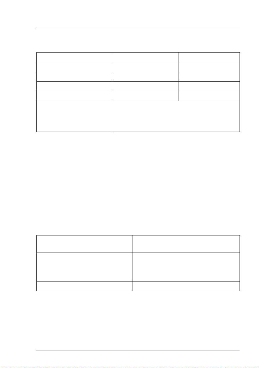
Mechanical specifications
Floorstand Rack
Width (with anti-tilt bracket) 205 mm (306 mm) 482 mm
Total depth 584 mm 570 mm
Installation depth ----- 596 mm
Height 444 mm 5 HU
Dimension notes Floorstand width 306 mm with tilt protection;
depth measured excludes handles on redundant
PSU. Rack depth excludes handles of
redundant PSU and rack front.
Weight
max. 36.8 kg (depending on configuration).
Ventilation clearance
At least 200 mm on the front and rear.
Maintenance area for the floorstand model
2
1.2 m
on the left side. Emergency access must be assured.
Ambient conditions
Environment class 3K2
Environment class 2K2
EN 60721 / IEC 721 Part 3-3
EN 60721 / IEC 721 Part 3-2
Temperature:
Operation (3K2) 10 °C .... 35 °C
Transport (2K2) -25 °C .... 60 °C
Humidity 10% .... 85% (non condensing)
Condensation during operation must be avoided!
TX200 S6 Operating Manual 27

Preface
Noise level with standard fan and standard power supply units
Sound power level L
(ISO 9296) ≤ 5.2 B (standby)
WAd
≤ 5.7 B (operating)
Sound pressure level at adjacent position
(ISO 9296)
L
pAm
≤ 34 dB (A) (standby)
≤ 36 dB (A) (operating)
Noise level with redundant system fans and redundant power supply
Sound power level L
(ISO 9296) ≤ 5.5 B (standby)
WAd
≤ 5.9 B (operating)
Sound pressure level at adjacent position
L
(ISO 9296)
pAm
≤ 36 dB (A) (standby)
≤ 39 dB (A) (operating)
28 Operating Manual TX200 S6

2 Installation steps, overview
This chapter contains an overview of the steps you need to carry out to install
your server. Links take you to sections where you can find more detailed
information about the respective steps:
Ê At first, please take notice of the safety instructions in chapter "Important
information" on page 31 and following.
Ê Unpack the system, check the contents of the package for visible transport
damage and check whether the items delivered match the details on the
delivery note (see section "Unpacking the server" on page 46).
Ê Transport the server to the place where you want to set it up.
Ê Make sure that you have all necessary manuals (see "Documentation
overview" on page 12); print out the PDF files if required.
Ê Components that have been ordered additionally may be delivered loose
with the server. Install these in the server as described in the supplied
documentation.
Ê Set up the floorstand model (see section "Setting up the floorstand model"
on page 47) or install the rack model in the rack (see section
"Installing/removing the rack model" on page 49).
Ê Wire the server. Follow the instructions in sections "Connecting devices to
the server" on page 59 and "Notes on connecting/disconnecting cables" on
page 63.
Ê Connect the server to the mains (see section "Connecting the server to the
mains" on page 60).
Ê Familiarize yourself with the controls and indicators on the front and rear of
the server (see section "Control elements and indicators" on page 68).
TX200 S6 Operating Manual 29

Installation steps, overview
Ê Configure the server and install the desired operating system and
applications. The following options are available:
– Remote installation with the ServerView Installation Manager:
With the ServerView Suite DVD 1 provided, you can configure the server
and install the operating system in a convenient manner.
Details on how to operate the ServerView Installation Manager, as well
as some additional information, are included in the "ServerView Suite
Installation Manager" user’s guide (on ServerView Suite DVD 2 under
Industry Standard Servers - Software - ServerView Suite - Server Installation
and Deployment).
Configuration information can also be found in section "Configuring the
server and installing the operating system with the ServerView
Installation Manager" on page 80.
– Local configuration and installation with or without the ServerView
Installation Manager (see section "Configuring the server and installing
the operating system with the ServerView Installation Manager" on
page 80 or section "Configuring the server and installing the operating
system without the ServerView Installation Manager" on page 81).
I You will find more information on installing the server remotely or
locally in the "ServerView Suite Installation Manager" user’s guide
(on the ServerView Suite DVD 2 under Industry Standard Servers -
Software - ServerView Suite - Server Installation and Deployment).
30 Operating Manual TX200 S6
Loading...