


 Loading...
Upgrade and Maintenance Manual - English
PRIMERGY MX130 S2
Server
Upgrade and Maintenance Manual
Edition November 2011
Comments… Suggestions… Corrections…
The User Documentation Department would like to know your opinion of this manual. Your feedback helps us optimize our documentation to suit your individual needs.
Feel free to send us your comments by e-mail to manuals@ts.fujitsu.com.
Certified documentation according to DIN EN ISO 9001:2008
To ensure a consistently high quality standard and user-friendliness, this documentation was created to meet the regulations of a quality management system which complies with the requirements of the standard DIN EN ISO 9001:2008.
cognitas. Gesellschaft für Technik-Dokumentation mbH www.cognitas.de
Copyright and Trademarks
Copyright © 2011 Fujitsu Technology Solutions GmbH.
All rights reserved.
Delivery subject to availability; right of technical modifications reserved.
All hardware and software names used are trademarks of their respective manufacturers.
–The contents of this manual may be revised without prior notice.
–Fujitsu assumes no liability for damages to third party copyrights or other rights arising from the use of any information in this manual.
–No part of this manual may be reproduced in any form without the prior written permission of Fujitsu.
Microsoft, Windows, Windows Server, and Hyper V are trademarks or registered trademarks of Microsoft Corporation in the USA and other countries.
AMD, the AMD Arrow Logo, AMD Athlon, AMD Sempron, AMD Opteron and combinations thereof are trademarks of Advanced Micro Devices, Inc. Other names are for informational purposes only and may be trademarks of their respective owners.

Before reading this manual
For your safety
This manual contains important information for safely and correctly using this product.
Carefully read the manual before using this product. Pay particular attention to the accompanying manual "Safety Notes and Regulations" and ensure these safety notes are understood before using the product. Keep this manual and the manual "Safety Notes and Regulations" in a safe place for easy reference while using this product.
Radio interference
This product is a "Class A" ITE (Information Technology Equipment). In a domestic environment this product may cause radio interference, in which case the user may be required to take appropriate measures. VCCI-A
Aluminum electrolytic capacitors
The aluminum electrolytic capacitors used in the product's printed circuit board assemblies and in the mouse and keyboard are limited-life components. Use of these components beyond their operating life may result in electrolyte leakage or depletion, potentially causing emission of foul odor or smoke.
As a guideline, in a normal office environment (25°C) operating life is not expected to be reached within the maintenance support period (5 years). However, operating life may be reached more quickly if, for example, the product is used in a hot environment. The customer shall bear the cost of replacing replaceable components which have exceeded their operating life. Note that these are only guidelines, and do not constitute a guarantee of trouble-free operation during the maintenance support period.
High safety use
This product has been designed and manufactured for general uses such as general office use, personal use, domestic use and normal industrial use. It has not been designed or manufactured for uses which demand an extremely high level of safety and carry a direct and serious risk to life or body if such safety cannot be ensured.
MX130 S2 |
Upgrade and Maintenance Manual |
3 |

These uses include control of nuclear reactions in nuclear power plants, automatic airplane flight control, air traffic control, traffic control in mass transport systems, medical devices for life support, and missile guidance control in weapons systems (hereafter, "high safety use"). Customers should not use this product for high safety use unless measures are in place for ensuring the level of safety demanded of such use. Please consult the sales staff of Fujitsu if intending to use this product for high safety use.
Measures against momentary voltage drop
This product may be affected by a momentary voltage drop in the power supply caused by lightning. To prevent a momentary voltage drop, use of an AC uninterruptible power supply is recommended.
(This notice follows the guidelines of Voltage Dip Immunity of Personal Computer issued by JEITA, the Japan Electronics and Information Technology Industries Association.)
Technology controlled by the Foreign Exchange and Foreign Trade Control Law of Japan
Documents produced by Fujitsu may contain technology controlled by the Foreign Exchange and Foreign Trade Control Law of Japan. Documents which contain such technology should not be exported from Japan or transferred to non-residents of Japan without first obtaining authorization in accordance with the above law.
Harmonic Current Standards
This product conforms to harmonic current standard JIS C 61000-3-2.
Only for the Japanese market: About SATA hard disk drives
The SATA version of this server supports hard disk drives with SATA / BC-SATA storage interfaces. Please note that the usage and operation conditions differ depending on the type of hard disk drive used.
Please refer to the following internet address for further information on the usage and operation conditions of each available type of hard disk drive:
http://primeserver.fujitsu.com/primergy/harddisk/
4 |
Upgrade and Maintenance Manual |
MX130 S2 |

Contents
Version history . . . . . . . . . . . . . . . . . . . . . . . . . . . . . . |
15 |
|
1 |
Introduction . . . . . . . . . . . . . . . . . . . . . . . . . . . |
17 |
1.1Where to find which information? . . . . . . . . . . . . . . . 18
1.2 |
Notational conventions . . . . . . . . . . . . . . . . . . . . |
19 |
2 |
Before you start . . . . . . . . . . . . . . . . . . . . . . . . |
21 |
2.1 |
Classification of procedures . . . . . . . . . . . . . . . . . |
23 |
2.1.1Customer Replaceable Units (CRU) . . . . . . . . . . . . . . . 23
2.1.2 |
Upgrade and Repair Units (URU) . . . . . . . . . . . . . . . . |
24 |
2.1.3 |
Field Replaceable Units (FRU) . . . . . . . . . . . . . . . . . |
25 |
2.2 |
Average task duration . . . . . . . . . . . . . . . . . . . . . |
26 |
2.3 |
Tools you need at hand . . . . . . . . . . . . . . . . . . . . |
27 |
2.4Documents you need at hand . . . . . . . . . . . . . . . . . 28
3 |
Important information . . . . . . . . . . . . . . . . . . . . . 31 |
3.1Safety instructions . . . . . . . . . . . . . . . . . . . . . . . 31
3.2 |
ENERGY STAR . . . . . . . . . . . . . . . . . . . . . . . . . |
39 |
3.3 |
CE conformity . . . . . . . . . . . . . . . . . . . . . . . . . |
42 |
3.4 |
FCC Class A Compliance Statement . . . . . . . . . . . . . |
43 |
3.5 |
Environmental protection . . . . . . . . . . . . . . . . . . . |
44 |
4 |
Basic hardware procedures . . . . . . . . . . . . . . . . . . |
47 |
4.1 |
Using diagnostics information . . . . . . . . . . . . . . . . |
47 |
4.2Opening the server . . . . . . . . . . . . . . . . . . . . . . . 48
4.2.1Shutting down the server
4.2.2Removing the server cover
. . . . . . . . . . . . . . . . . . . . 48
. . . . . . . . . . . . . . . . . . . 51
MX130 S2 |
Upgrade and Maintenance Manual |
5 |

Contents
4.3 |
Opening the front cage . . . . . . . . . . . . . . . . . . . . . 52 |
4.4Closing the front cage . . . . . . . . . . . . . . . . . . . . . . 53
4.5Closing the server . . . . . . . . . . . . . . . . . . . . . . . . 54
4.5.1 |
Mounting the server cover . . . . . . . . . . . . . . . . . . . . 54 |
4.5.2Connecting the server to the mains . . . . . . . . . . . . . . . . 55
4.6Switching on the server . . . . . . . . . . . . . . . . . . . . . 58
5 |
Basic software procedures . . . . . . . . . . . . . . . . . . . 59 |
|
5.1 |
Starting the maintenance task |
. . . . . . . . . . . . . . . . . 59 |
5.1.1 |
Disabling BitLocker functionality |
. . . . . . . . . . . . . . . . . 59 |
5.1.2 |
Removing backup and optical disk media . . . . . . . . . . . . 60 |
|
5.1.3Verifying and configuring the backup software solution . . . . . . 61
5.2 |
Completing the maintenance task . . . . . . . . . . . . . . . 62 |
5.2.1Updating the system board BIOS . . . . . . . . . . . . . . . . . 62
5.2.2Updating RAID controller firmware . . . . . . . . . . . . . . . . 63
5.2.3Enabling Option ROM scan . . . . . . . . . . . . . . . . . . . . 64
5.2.4Verifying and configuring the backup software solution . . . . . . 64
5.2.5Viewing the System Event Log (SEL) . . . . . . . . . . . . . . . 65
5.2.6Enabling BitLocker functionality . . . . . . . . . . . . . . . . . . 66
5.2.7 |
Performing a RAID array rebuild . . . . . . . . . . . . . . . . . 67 |
5.2.8Looking up changed MAC addresses . . . . . . . . . . . . . . . 67
5.2.9 |
Using the Chassis ID Prom Tool |
. . . . . . . . . . . . . . . . . 68 |
6 |
Power supply . . . . . . . . . |
. . . . . . . . . . . . . . . . . 69 |
6.1 |
Standard PSU . . . . . . . . . |
. . . . . . . . . . . . . . . . . 70 |
6.1.1 |
Replacing the standard PSU . . |
. . . . . . . . . . . . . . . . . 70 |
6.1.1.1Required tools . . . . . . . . . . . . . . . . . . . . . . . . . 70
6.1.1.2 |
Preliminary steps . . . . . . . . . |
. . . . . . . . . . . . . . 70 |
6.1.1.3 |
Disconnecting internal power cables |
. . . . . . . . . . . . . 71 |
6.1.1.4 |
Removing the PSU . . . . . . . . |
. . . . . . . . . . . . . . 72 |
6.1.1.5Installing the PSU . . . . . . . . . . . . . . . . . . . . . . . 73
6.1.1.6 |
Reconnecting internal power cables |
. . |
. . |
. . . |
. |
. |
. . . |
. |
76 |
6.1.1.7 |
Concluding steps . . . . . . . . . |
. . . |
. . |
. . . |
. |
. |
. . . |
. |
77 |
6 |
Upgrade and Maintenance Manual |
MX130 S2 |

Contents
7 |
HDDs and accessible drives . . . . . . . . . . . . . . . . . . |
79 |
7.1 |
Basic procedure . . . . . . . . . . . . . . . . . . . . . . . . |
81 |
7.2Mounting order . . . . . . . . . . . . . . . . . . . . . . . . . 82
7.3 |
Installing 3.5-inch HDD in HDD1 / HDD2 chassis bay . . . . 83 |
7.3.1Required tools . . . . . . . . . . . . . . . . . . . . . . . . . . 83
7.3.2 |
Preliminary steps . . . . . . . . . . . . . . . . . . . . . . . . 83 |
7.3.3Installing a 3.5-inch HDD in HDD 1/HDD 2 chassis bay . . . . . 84
7.3.4 |
Concluding steps . . . . . . . . . . . . . . . . . . . . . . . . |
87 |
7.4 |
Removing 3.5-inch HDD out of HDD1 / HDD2 chassis bay . |
88 |
7.4.1Required tools . . . . . . . . . . . . . . . . . . . . . . . . . . 88
7.4.2 |
Preliminary steps . . . . . . . . . . . . . . . . . . . . . . . . 88 |
7.4.3Removing a 3.5-inch HDD out of HDD 1/HDD 2 chassis bay . . 89
7.4.4 |
Concluding steps . . . . . . . . . . . . . . . . . . . . . . . . |
91 |
7.5 |
Installing additional 3.5-inch HDD in 3.5-inch chassis bay . |
91 |
7.5.1Required tools . . . . . . . . . . . . . . . . . . . . . . . . . . 91
7.5.2 |
Preliminary steps . . . . . . . . . . . . . . . . . . . . . . . . 91 |
7.5.3Installing an additional 3.5-inch HDD in 3.5-inch chassis bay . . 92
7.5.4 |
Concluding steps . . . . . . . . . . . . . . . . . . . . . . . . 93 |
7.6Removing additional 3.5-inch HDD out of
3.5-inch chassis bay . . . . . . . . . . . . . . . . . . . . . . 94
7.6.1Required tools . . . . . . . . . . . . . . . . . . . . . . . . . . 94
7.6.2 |
Preliminary steps . . . . . . . . . . . . . . . . . . . . . . . . 94 |
7.6.3Removing an additional 3.5-inch HDD out of 3.5-inch chassis bay . 95
7.6.4 |
Concluding steps . . . . . . . . . . . . . . . . . . . . . . . . |
96 |
7.7 |
Installing additional 3.5-inch HDD in |
|
|
5.25-inch dummy cover . . . . . . . . . . . . . . . . . . . . |
97 |
7.7.1Required tools . . . . . . . . . . . . . . . . . . . . . . . . . . 97
7.7.2 |
Preliminary steps . . . . . . . . . . . . . . . . . . . . . . . . |
97 |
7.7.3 |
Installing a 3.5-inch HDD in 5.25-inch dummy cover . . . . . . |
98 |
7.7.4 |
Concluding steps . . . . . . . . . . . . . . . . . . . . . . . . 100 |
|
7.8 |
Removing 3.5-inch HDD out of |
|
|
5.25-inch dummy cover . . . . . . . . . . . . . . . . . . . . 100 |
|
7.8.1Required tools . . . . . . . . . . . . . . . . . . . . . . . . . . 100
7.8.2 |
Preliminary steps . . . . . . . . . . . . . . . . . . . . . . . . 100 |
7.8.3Removing a 3.5-inch HDD out of 5.25-inch dummy cover . . . . 101
7.8.4 |
Concluding steps . . . . . . . . . . . . . . . . . . . . . . . . 103 |
MX130 S2 |
Upgrade and Maintenance Manual |
7 |

Contents
7.9Installing additional 3.5-inch HDD in 5.25-inch ODD/HDD
|
bracket . . . . . . . . . . . . . . . . . . . . . . . . . . . . . |
103 |
7.9.1 |
Required tools . . . . . . . . . . . . . . . . . . . . . . . . . |
103 |
7.9.2 |
Preliminary steps . . . . . . . . . . . . . . . . . . . . . . . . |
103 |
7.9.3 |
Installing an additional 3.5-inch HDD in ODD/HDD bracket . . |
104 |
7.9.4 |
Concluding steps . . . . . . . . . . . . . . . . . . . . . . . . |
106 |
7.10Removing 3.5-inch HDD out of 5.25-inch
ODD/HDD bracket . . . . . . . . . . . . . . . . . . . . . . . 106
7.10.1 |
Required tools . . . . . . . . . . . . . . . . . . . . . . . . . |
106 |
7.10.2 |
Preliminary steps . . . . . . . . . . . . . . . . . . . . . . . . |
107 |
7.10.3Removing an additional 3.5-inch HDD out of the
|
5.25-inch ODD/HDD bracket . . . . . . . . . . . . . . . . . . |
107 |
7.10.4 |
Concluding steps . . . . . . . . . . . . . . . . . . . . . . . . |
110 |
7.11 |
Installing 5.25-inch dummy cover . . . . . . . . . . . . . . |
110 |
7.11.1 |
Required tools . . . . . . . . . . . . . . . . . . . . . . . . . |
110 |
7.11.2 |
Preliminary steps . . . . . . . . . . . . . . . . . . . . . . . . |
110 |
7.11.3Installing a 5.25-inch dummy cover . . . . . . . . . . . . . . . 111
7.11.4 Concluding steps . . . . . . . . . . . . . . . . . . . . . . . . 112
7.12Removing 5.25-inch dummy cover . . . . . . . . . . . . . . 112
7.12.1 |
Required tools . . . . . . . . . . . . . . . . . . . . . . . . . |
112 |
7.12.2 |
Preliminary steps . . . . . . . . . . . . . . . . . . . . . . . . |
112 |
7.12.3Removing a 5.25-inch dummy cover . . . . . . . . . . . . . . 113
7.12.4 Concluding steps . . . . . . . . . . . . . . . . . . . . . . . . 114
7.13Installing ODD in 5.25-inch chassis bay . . . . . . . . . . . 115
7.13.1 |
Required tools . . . . . . . . . . . . . . . . . . . . . . . . . |
115 |
7.13.2 |
Preliminary steps . . . . . . . . . . . . . . . . . . . . . . . . |
115 |
7.13.3Installing an ODD in 5.25-inch chassis bay . . . . . . . . . . . 116
7.13.4 Concluding steps . . . . . . . . . . . . . . . . . . . . . . . . 117
7.14Removing ODD out of 5.25-inch chassis bay . . . . . . . . 118
7.14.1 |
Required tools . . . . . . . . . . . . . . . . . . . . . . . . . |
118 |
7.14.2 |
Preliminary steps . . . . . . . . . . . . . . . . . . . . . . . . |
118 |
7.14.3Removing an ODD out of 5.25-inch chassis bay . . . . . . . . 119
7.14.4 Concluding steps . . . . . . . . . . . . . . . . . . . . . . . . 120
7.15Installing slimline ODD in 5.25-inch ODD/HDD bracket . . . 121
7.15.1 |
Required tools . . . . . . . . . . . . . . . . . . . . . |
. . . . 121 |
|
7.15.2 |
Preliminary steps . . . . . . . . . . . . . . . . . . . . |
. . . . 121 |
|
7.15.3 |
Installing a slimline ODD in 5.25-inch ODD/HDD bracket |
. . . |
122 |
7.15.4 |
Concluding steps . . . . . . . . . . . . . . . . . . . . |
. . . . |
124 |
8 |
Upgrade and Maintenance Manual |
MX130 S2 |

Contents
7.16Removing slimline ODD out of 5.25-inch
ODD/HDD bracket . . . . . . . . . . . . . . . . . . . . . . . 125
7.16.1Required tools . . . . . . . . . . . . . . . . . . . . . . . . . . 125
7.16.2 |
Preliminary steps . . . . . . . . . . . . . . . . . . . . . . . . 125 |
7.16.3Removing a slimline ODD out of 5.25-inch ODD/HDD bracket . 126
7.16.4 |
Concluding steps . . . . . . . . . . . . . . . . . . . . . . . . 129 |
7.17Installing backup drive in 5.25-inch chassis bay . . . . . . . 130
7.17.1Required tools . . . . . . . . . . . . . . . . . . . . . . . . . . 130
7.17.2 |
Preliminary steps . . . . . . . . . . . . . . . . . . . . . . . . 130 |
7.17.3Installing a backup drive in 5.25-inch chassis bay . . . . . . . . 131
7.17.4 |
Concluding steps . . . . . . . . . . . . . . . . . . . . . . . . 132 |
7.18Removing backup drive out of 5.25-inch chassis bay . . . . 133
7.18.1Required tools . . . . . . . . . . . . . . . . . . . . . . . . . . 133
7.18.2 |
Preliminary steps . . . . . . . . . . . . . . . . . . . . . . . . 133 |
7.18.3Removing backup drive out of 5.25-inch chassis bay . . . . . . 134
7.18.4 |
Concluding steps . . . . . . . . . . . . . . . . . |
. . . . |
. |
. |
. 135 |
7.19 |
Installing slimline ODD in slimline chassis bay |
. . . . |
. |
. |
. 136 |
7.19.1Required tools . . . . . . . . . . . . . . . . . . . . . . . . . . 136
7.19.2 |
Preliminary steps . . . . . . |
. . . . |
. . . . . . . . |
. |
. . . |
. |
. 136 |
7.19.3 |
Removing the ODD filler cover |
. . . |
. . . . . . . . |
. |
. . . |
. |
. 137 |
7.19.4Installing the ODD . . . . . . . . . . . . . . . . . . . . . . . . 138
7.19.5 |
Concluding steps . . . . . . . . . . . . . . . . . . . |
. . |
. |
. |
. 141 |
7.20 |
Replacing slimline ODD out of slimline chassis bay |
. |
. |
. |
. 142 |
7.20.1Required tools . . . . . . . . . . . . . . . . . . . . . . . . . . 142
7.20.2 |
Preliminary steps . . . . . . . . . . . . . . . . . . . . . . . . 142 |
7.20.3Replacing a slimline ODD out of slimline chassis bay . . . . . . 143
7.20.4 |
Concluding steps |
. . . . . . . . . . |
. . . . . . . |
. . . . |
. |
. |
. 144 |
8 |
System fan . . . |
. . . . . . . . . . |
. . . . . . . |
. . . . |
. |
. |
. 145 |
8.1Replacing the system fan module . . . . . . . . . . . . . . . 146
8.1.1Required tools . . . . . . . . . . . . . . . . . . . . . . . . . . 146
8.1.2 |
Preliminary steps . . . . . . . . . . . . . . . . . . . . . . . . 146 |
8.1.3Removing the system fan module . . . . . . . . . . . . . . . . 147
8.1.4 |
Installing the system fan module |
. . |
. . |
. . |
. . . |
. |
. |
. |
. |
. |
. |
. 150 |
8.1.5 |
Concluding steps . . . . . . . |
. . . |
. . |
. . |
. . . |
. |
. |
. |
. |
. |
. |
. 157 |
MX130 S2 |
Upgrade and Maintenance Manual |
9 |

Contents
9 |
Expansion cards . . . . . . . . . . . . . . . . . . . . . . . . 159 |
9.1Basic procedure . . . . . . . . . . . . . . . . . . . . . . . . 160
9.2Expansion cards . . . . . . . . . . . . . . . . . . . . . . . . 161
9.2.1 |
Installing expansion cards . . . . . . . . . . . . . . . . . . . 161 |
9.2.1.1Required tools . . . . . . . . . . . . . . . . . . . . . . . . 161
9.2.1.2 |
Preliminary steps . . . . . . |
. . . . . . . . . . . . . . . . |
161 |
9.2.1.3 |
Removing a PCI slot bracket |
. . . . . . . . . . . . . . . . |
162 |
9.2.1.4Installing an expansion card . . . . . . . . . . . . . . . . . 163
9.2.1.5Connecting cables to the expansion card . . . . . . . . . . 165
9.2.1.6 |
Concluding steps . . . . . . . . . . . . . . . . . . . . . . 165 |
9.2.2Removing expansion cards . . . . . . . . . . . . . . . . . . . 165
9.2.2.1Required tools . . . . . . . . . . . . . . . . . . . . . . . . 165
9.2.2.2 |
Preliminary steps . . . . . . . . . . . . . . . . . . . . . . 166 |
9.2.2.3Removing an expansion card . . . . . . . . . . . . . . . . 166
9.2.2.4Installing a PCI slot bracket . . . . . . . . . . . . . . . . . 167
9.2.2.5 |
Concluding steps |
. . . . . . . . . . . . . . . . . . . . . . |
167 |
9.2.3 |
Installing eSATA cable |
. . . . . . . . . . . . . . . . . . . . . |
168 |
9.2.3.1Required tools . . . . . . . . . . . . . . . . . . . . . . . . 168
9.2.3.2 |
Preliminary steps . . . . . . . . . . . . . . . . . . . . . . 168 |
9.2.3.3Installing an eSATA cable (optional for specific markets) . . 168
9.2.3.4Connecting cable of the eSATA cable to connector . . . . . 170
9.2.3.5 |
Concluding steps . . . . . . . . . . . . . . . . . . . . . . 170 |
9.2.4Removing eSATA cable . . . . . . . . . . . . . . . . . . . . . 170
9.2.4.1Required tools . . . . . . . . . . . . . . . . . . . . . . . . 171
9.2.4.2 |
Preliminary steps . . . . . . . . . . . . . . . . . . . . . . 171 |
9.2.4.3Disconnecting eSATA cable (optional for specific markets) . 171
9.2.4.4 |
Removing an eSATA cable . . . . . . . . . . . . . . . . . |
172 |
9.2.4.5 |
Concluding steps . . . . . . . . . . . . . . . . . . . . . . |
172 |
9.3Additional tasks . . . . . . . . . . . . . . . . . . . . . . . . 173
9.3.1Mounting expansion card slot brackets . . . . . . . . . . . . . 173
9.3.1.1Required tools . . . . . . . . . . . . . . . . . . . . . . . . 173
9.3.1.2Network adapter D2907 . . . . . . . . . . . . . . . . . . . 174
9.3.1.3Network adapter D2745 . . . . . . . . . . . . . . . . . . . 176
10 |
Main memory . . . . . . . . . . . . . . . . . . . . . . . . . 179 |
10.1Basic procedure . . . . . . . . . . . . . . . . . . . . . . . . 180
10.1.1 Memory sequence . . . . . . . . . . . . . . . . . . . . . . . 180
10.1.2Operation modes . . . . . . . . . . . . . . . . . . . . . . . . 181
10 |
Upgrade and Maintenance Manual |
MX130 S2 |
Contents
10.2 |
Installing memory modules . . . . . . . . . . . . . . . . . . 182 |
10.2.1Required tools . . . . . . . . . . . . . . . . . . . . . . . . . . 182
10.2.2 |
Preliminary steps . . . . . . . . . . . . . . . . . . . . . . . . 182 |
10.2.3Installing a memory module . . . . . . . . . . . . . . . . . . . 182
10.2.4 |
Concluding steps . . . . . . . . . . . . . . . . . . . . . . . . 183 |
10.3Removing memory modules . . . . . . . . . . . . . . . . . . 184
10.3.1Required tools . . . . . . . . . . . . . . . . . . . . . . . . . . 184
10.3.2 |
Preliminary steps . . . . . . . . . . |
. . . . . . . . . . . . . . 184 |
10.3.3 |
Removing a memory module . . . . |
. . . . . . . . . . . . . . 184 |
10.3.4 |
Concluding steps . . . . . . . . . . |
. . . . . . . . . . . . . . 185 |
11 |
Processors . . . . . . . . . . . . . |
. . . . . . . . . . . . . . 187 |
11.1 |
Basic procedure . . . . . . . . . . |
. . . . . . . . . . . . . . 188 |
11.2 |
Replacing the processor heat sink |
. . . . . . . . . . . . . . 188 |
11.2.1Required tools . . . . . . . . . . . . . . . . . . . . . . . . . . 188
11.2.2 |
Preliminary steps . . . . . . . . . |
. . |
. . . . . . . . |
. . |
. . |
. 188 |
11.2.3 |
Removing the processor heat sink |
. . |
. . . . . . . . |
. . |
. . |
. 189 |
11.2.4Thermal paste . . . . . . . . . . . . . . . . . . . . . . . . . . 190
11.2.5 |
Installing the processor heat sink |
. . |
. . . . |
. . . . . . . . |
. |
. 190 |
11.2.6 |
Concluding steps . . . . . . . |
. . . |
. . . . |
. . . . . . . . |
. |
. 191 |
11.3Replacing the processor . . . . . . . . . . . . . . . . . . . . 191
11.3.1Required tools . . . . . . . . . . . . . . . . . . . . . . . . . . 191
11.3.2 |
Preliminary steps . . . . . . . . . |
. . |
. . . . . . . . |
. . |
. . |
. 192 |
11.3.3 |
Removing the processor heat sink |
. . |
. . . . . . . . |
. . |
. . |
. 192 |
11.3.4Removing the processor . . . . . . . . . . . . . . . . . . . . . 192
11.3.5 |
Installing the processor . . . . |
. . . . . . . . . . . . . . . . . 194 |
11.3.6 |
Applying thermal paste . . . . |
. . . . . . . . . . . . . . . . . 196 |
11.3.7 |
Installing the processor heat sink |
. . . . . . . . . . . . . . . . 197 |
11.3.8 |
Concluding steps . . . . . . . . . . . . . . . . . . . . . . . . 197 |
|
12 |
System board and components . . . . . . . . . . . . . . . . 199 |
|
12.1 |
Replacing the CMOS battery |
. . . . . . . . . . . . . . . . . 200 |
12.1.1Required tools . . . . . . . . . . . . . . . . . . . . . . . . . . 200
12.1.2 |
Preliminary steps . . . . . |
. . . . . . |
. . . |
. . . . . |
. |
. |
. |
. |
. 201 |
12.1.3 |
Removing the CMOS battery |
. . . . . |
. . . |
. . . . . |
. |
. |
. |
. |
. 201 |
12.1.4Installing the CMOS battery . . . . . . . . . . . . . . . . . . . 202
12.1.5 |
Concluding steps . . . . . . . . . . . . . . . . . . . . . . . . 203 |
MX130 S2 |
Upgrade and Maintenance Manual |
11 |

Contents
12.2Trusted Platform Module (TPM) . . . . . . . . . . . . . . . . 204
12.2.1 |
Installing the TPM board . . . . . . . . . . . . . . . . . . . . 204 |
12.2.1.1Required tools . . . . . . . . . . . . . . . . . . . . . . . . 204
12.2.1.2 |
Preliminary steps . . . . |
. . . . . . . . . . . . . . . . . . |
204 |
12.2.1.3 |
Installing the TPM board |
. . . . . . . . . . . . . . . . . . |
205 |
12.2.1.4 |
Concluding steps . . . . |
. . . . . . . . . . . . . . . . . . |
208 |
12.2.2Removing the TPM board . . . . . . . . . . . . . . . . . . . . 209
12.2.2.1Required tools . . . . . . . . . . . . . . . . . . . . . . . . 209
12.2.2.2 |
Preliminary steps . . . . . . . . . . . . . . . . . . . . . . 210 |
12.2.2.3Removing the TPM board . . . . . . . . . . . . . . . . . . 211
12.2.2.4 |
Concluding steps . . . . |
. . . . . . . . . . . . . . . . . . |
212 |
12.3 |
Replacing the system board |
. . . . . . . . . . . . . . . . . |
213 |
12.3.1 |
Required tools . . . . . . . |
. . . . . . . . . . . . . . . . . . |
213 |
12.3.2 |
Preliminary steps . . . . . . |
. . . . . . . . . . . . . . . . . . |
214 |
12.3.3 |
Removing the system board |
. . . . . . . . . . . . . . . . . . |
215 |
12.3.4Installing the system board . . . . . . . . . . . . . . . . . . . 218
12.3.4.1Mounting the system board . . . . . . . . . . . . . . . . . 218
12.3.5 |
Concluding steps . . . . . . . . . . . . . . . . . . . . . . . . |
221 |
13 |
Front panel and front USB . . . . . . . . . . . . . . . . . . |
223 |
13.1 |
Replacing the front panel indicators . . . . . . . . . . . . |
224 |
13.1.1 |
Required tools . . . . . . . . . . . . . . . . . . . . . . . . . |
224 |
13.1.2 |
Preliminary steps . . . . . . . . . . . . . . . . . . . . . . . . |
224 |
13.1.3 |
Removing the On/Off button . . . . . . . . . . . . . . . . . . |
225 |
13.1.4 |
Removing the HDD activity LED . . . . . . . . . . . . . . . . |
226 |
13.1.5 |
Removing the cable for On/Off button and HDD activity LED . |
227 |
13.1.6Installing the On/Off button and the HDD activity LED . . . . . 228
13.1.7 Concluding steps . . . . . . . . . . . . . . . . . . . . . . . . 228
13.2Replacing the front USB board . . . . . . . . . . . . . . . . 229
13.2.1 |
Required tools . . . . . . . . . . . . . . . . . . . . . . . . . |
229 |
13.2.2 |
Preliminary steps . . . . . . . . . . . . . . . . . . . . . . . . |
229 |
13.2.3Removing the defective front USB board . . . . . . . . . . . . 230
13.2.4Installing the new front USB board . . . . . . . . . . . . . . . 231
13.2.5 |
Concluding steps |
. . . . . . . . . . . . . . . . . . . . . . . . |
232 |
14 |
Cables . . . . . |
. . . . . . . . . . . . . . . . . . . . . . . . |
233 |
14.1 |
Cabling overview |
. . . . . . . . . . . . . . . . . . . . . . . |
234 |
12 |
Upgrade and Maintenance Manual |
MX130 S2 |

Contents
14.1.1Overview of used cables . . . . . . . . . . . . . . . . . . . . . 234
14.2 |
Cabling . . . |
. . . . . . . |
. |
. . . . |
. . |
. . . . . |
. . . . . |
. |
. 235 |
14.2.1 |
Power cabling |
. . . . . . . |
. |
. . . . |
. . |
. . . . . |
. . . . . |
. |
. 235 |
14.2.2Data cabling . . . . . . . . . . . . . . . . . . . . . . . . . . . 237
14.3 |
Replacing the power cable . . . . . . . . . . . . . . . . . . 239 |
14.3.1Required tools . . . . . . . . . . . . . . . . . . . . . . . . . . 239
14.3.2 |
Preliminary steps . . . . |
. . . . . . . . . . . . . . . . . . . . 239 |
14.3.3 |
Removing the power cable |
. . . . . . . . . . . . . . . . . . . 240 |
14.3.4 |
Installing the power cable |
. . . . . . . . . . . . . . . . . . . . 242 |
14.3.5 |
Concluding steps . . . . |
. . . . . . . . . . . . . . . . . . . . 243 |
15 |
Appendix . . . . . . . . |
. . . . . . . . . . . . . . . . . . . . 245 |
15.1Mechanical overview . . . . . . . . . . . . . . . . . . . . . . 245
15.1.1 |
Server front . . . . . . . . . . . . . . . . . . . . . . . . . . . 245 |
15.1.2Server rear . . . . . . . . . . . . . . . . . . . . . . . . . . . . 246
15.1.3 |
Server interior . . . . . . . . . . . . . . . . . . . . . . . . . . 247 |
15.2Configuration tables . . . . . . . . . . . . . . . . . . . . . . 248
15.2.1 |
Mounting order for HDDs . . . . . . . . . . . . . . . . . . . . 248 |
15.2.2Memory board configuration . . . . . . . . . . . . . . . . . . . 248
15.2.3 |
Expansion card configuration table . . . . . . |
. . . . . . . . . 248 |
15.3 |
Connectors and indicators . . . . . . . . . |
. . . . . . . . . 249 |
15.3.1 |
Connectors and indicators on the system board |
. . . . . . . . 249 |
15.3.1.1Onboard connectors . . . . . . . . . . . . . . . . . . . . . 249
15.3.1.2Onboard settings . . . . . . . . . . . . . . . . . . . . . . . 250
15.3.1.3I/O panel connectors . . . . . . . . . . . . . . . . . . . . . 251
15.3.1.4I/O panel indicators . . . . . . . . . . . . . . . . . . . . . . 252
15.3.2 |
Connectors and indicators on the front panel . . . . . . . . . . 253 |
15.4Minimum startup configuration . . . . . . . . . . . . . . . . 254
MX130 S2 |
Upgrade and Maintenance Manual |
13 |

Contents
14 |
Upgrade and Maintenance Manual |
MX130 S2 |

Version history
Issue number |
Reason for update |
|
Initial release |
|
|
|
|
|
|
|
|
MX130 S2 |
Upgrade and Maintenance Manual |
15 |

Version history
16 |
Upgrade and Maintenance Manual |
MX130 S2 |

1 Introduction
This Upgrade and Maintenance Manual provides instructions for the following procedures:
●Upgrading the server configuration by adding optional hardware components
●Upgrading the server configuration by replacing existing hardware components with superior ones.
●Replacing defective hardware components
VCAUTION!
The document at hand comprises procedures of a wide range of complexity. Check the profile of qualification for technicians before assigning tasks. Before you start, carefully read "Classification of procedures" on page 23.
MX130 S2 |
Upgrade and Maintenance Manual |
17 |

Introduction
1.1Where to find which information?
While the Upgrade and Maintenance Manual focuses on upgrade and maintenance procedures to bring the server back to normal operation, additional manuals provide detailed background information on server components and BIOS settings.
For information on documents you need to have with you when leaving for maintaining a server see "Documents you need at hand" on page 28.
IPRIMERGY manuals are available in PDF format on the ServerView Suite DVD 2. The ServerView Suite DVD 2 is part of the ServerView Suite supplied with every server.
If you no longer have the ServerView Suite DVDs, you can obtain the relevant current versions using the order number U15000-C289 (the order number for the Japanese market: please refer to the configurator of the server http://primeserver.fujitsu.com/primergy/system/).
The PDF files of the manuals can also be downloaded free of charge from the Internet. The overview page showing the online documentation available on the Internet can be found using the URL (for EMEA market): http://manuals.ts.fujitsu.com. The PRIMERGY server documentation can be accessed using the Industry standard servers navigation option.
For the Japanese market:
Please refer to the following URL for the latest product manuals: http://primeserver.fujitsu.com/primergy/manual/
Before using the product, please check for additional information that may be available under the following URL: http://primeserver.fujitsu.com/primergy/products/note/
18 |
Upgrade and Maintenance Manual |
MX130 S2 |

Introduction
1.2Notational conventions
The following notational conventions are used in this manual:
Text in italics |
indicates commands or menu items |
fixed font |
indicates system output |
semi-bold fixed indicates text to be entered by the user font
"Quotation marks" indicate names of chapters and terms that are being |
|
|
emphasized |
|
|
Ê |
describes activities that must be performed in the order |
|
shown |
[Abc] |
indicates keys on the keyboard |
VCAUTION! Pay particular attention to texts marked with this symbol! Failure to observe this warning may endanger your life, destroy the system or lead to the loss of data.
Iindicates additional information, notes and tips
indicates the procedure category in terms of complexity and qualification requirements, see "Classification of procedures" on page 23
indicates the average task duration, see "Average task duration" on page 26
MX130 S2 |
Upgrade and Maintenance Manual |
19 |

Introduction
20 |
Upgrade and Maintenance Manual |
MX130 S2 |
2 Before you start
Before you start any upgrade or maintenance task, please proceed as follows:
ÊCarefully read the safety instructions in chapter "Important information" on page 31.
ÊMake sure that all necessary manuals are available. Refer to the documentation overview in section "Documents you need at hand" on page 28. Print the PDF files if required.
ÊMake yourself familiar with the procedure categories introduced in section "Classification of procedures" on page 23.
ÊEnsure that all required tools are available according to section "Tools you need at hand" on page 27.
Installing optional components
The "PRIMERGY MX130 S2 Server Operating manual" gives an introduction to server features and provides an overview of available hardware options.
Use the Fujitsu ServerView Suite management software to prepare hardware expansions. ServerView Suite documentation is available online at http://manuals.ts.fujitsu.com (http://primeserver.fujitsu.com/primergy/system/ (for the Japanese market) or from the ServerView Suite DVD 2 supplied with your PRIMERGY server. Please refer to the following ServerView Suite topics:
–Operation
–Virtualization
–Maintenance
IFor the latest information on hardware options, refer to your server’s hardware configurator available online at the following address:
for the EMEA market: http://ts.fujitsu.com/products/standard_servers/micro_server/primergy_mx130 s2x.html
for the Japanese market: http://primeserver.fujitsu.com/primergy/system/
MX130 S2 |
Upgrade and Maintenance Manual |
21 |

Before you start
Please contact your local Fujitsu customer service partner for details on how to order expansion kits or spare parts. Use the Fujitsu Illustrated Spares Catalog to identify the required spare part and obtain technical data and order information. Illustrated Spares catalogs are available online at http://manuals.ts.fujitsu.com/illustrated_spares (EMEA market only).
22 |
Upgrade and Maintenance Manual |
MX130 S2 |
Before you start
2.1Classification of procedures
The complexity of maintenance procedures varies significantly. Procedures have been assigned to one of three unit categories, indicating the level of difficulty and required qualification.
At the beginning of each procedure, the involved unit type is indicated by one of the symbols introduced in this section.
IPlease ask your local Fujitsu service center for more detailed information.
2.1.1Customer Replaceable Units (CRU)
Customer Replaceable Units (CRU)
Non hot-plug peripherals that are handled as Customer Replaceable Units
–Keyboard
–Mouse
MX130 S2 |
Upgrade and Maintenance Manual |
23 |

Before you start
2.1.2Upgrade and Repair Units (URU)
 Upgrade and Repair Units (URU)
Upgrade and Repair Units are non hot-plug components that can be ordered separately to be installed as options (Upgrade Units).
Upgrade and repair procedures involve shutting down and opening the server.
VCAUTION!
The device may be seriously damaged or cause damage if it is opened without authorization or if repairs are attempted by unauthorized and untrained personnel.
Components that are handled as Upgrade Units
–Processors (upgrade kits)
–ODDs
–Backup drives
–Expansion cards
–Memory modules
–Non hot-plug HDDs
Components that are handled solely as Repair Units
–CMOS battery
–Non hot-plug fans
24 |
Upgrade and Maintenance Manual |
MX130 S2 |

Before you start
2.1.3Field Replaceable Units (FRU)
Field Replaceable Units (FRU)
Removing and installing Field Replaceable Units involves complex maintenance procedures on integral server components. Procedures will require shutting down, opening and disassembling the server.
VCAUTION!
Maintenance procedures involving Field Replaceable Units must be performed exclusively by Fujitsu service personnel or technicians trained by Fujitsu. Please note that unauthorized interference with the system will void the warranty and exempt the manufacturer from all liability.
Components that are handled as Field Replaceable Units
–Processors (replacements)
–Front panel (the On/Off button and the HDD activity LED)
–System board
–Standard PSU
–Trusted Platform Module (TPM)
IPlease ask your local Fujitsu service center for more detailed information.
MX130 S2 |
Upgrade and Maintenance Manual |
25 |

Before you start
2.2Average task duration
Average task duration: 10 minutes
The average task duration including preliminary and concluding steps is indicated at the beginning of each procedure next to the procedure class.
Refer to table 1 on page 26 for an overview of steps taken into account for calculating the average task duration:
Step |
included |
Explanation |
|
|
|
|
|
|
|
Shutdown time depends on hardware and |
|
Server shutdown |
no |
software configuration and may vary |
|
|
|
significantly. |
|
|
|
|
|
Disassembly |
yes |
making the server available |
|
|
|
|
|
|
|
Transporting the server to the service table |
|
Transport |
no |
(where required) depends on local |
|
|
|
customer conditions. |
|
Maintenance |
yes |
maintenance procedures including |
|
procedures |
preliminary and concluding software tasks |
||
|
|||
|
|
|
|
|
|
Returning the server to its installation site |
|
Transport |
no |
(where required) depends on local |
|
|
|
customer conditions. |
|
|
|
|
|
Assembly |
yes |
reassembling the server |
|
|
|
|
|
|
|
Booting time depends on hardware and |
|
Starting up |
no |
software configuration and may vary |
|
|
|
significantly. |
|
|
|
|
Table 1: Calculation of the average task duration
26 |
Upgrade and Maintenance Manual |
MX130 S2 |
Before you start
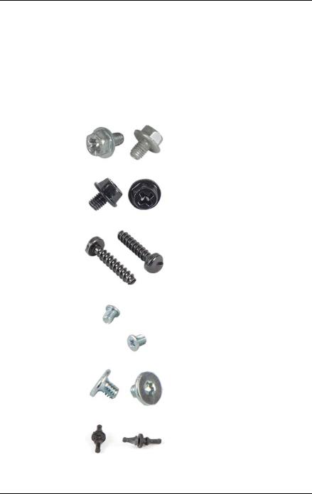
2.3Tools you need at hand
When preparing the maintenance task, ensure that all required tools are available according to the overview below. You will find a list of required tools at the beginning of each procedure.
Screw driver / |
Screw |
Usage |
Type |
|
Bit insert |
||||
|
|
|
||
Phillips |
|
Board, |
M3 x 4.5 mm |
|
PH2 / (+) No. 2 |
|
(silver) |
||
hexagonal cross |
|
Front USB |
C26192-Y10-C67 |
|
SW5 / PZ2 |
|
|
||
|
|
|
|
|
Phillips |
|
|
UNC |
|
PH2 / (+) No. 2 |
|
HDD3, HDD4 |
6-32 x 4.76 mm |
|
hexagonal cross |
|
(black) |
||
SW5 / PZ2 |
|
|
C26192-Y10-C75 |
|
|
|
|
|
|
TPM bit insert |
|
TPM screw |
REM 3 x 15 mm |
|
Dedicated TPM |
|
|||
|
One way |
(black) |
||
screw driver / |
|
|||
|
head |
|
||
TPM module |
|
C26192-Y10- |
||
|
|
|||
fixing tool (for the |
|
(black) |
C176 |
|
Japanese market) |
|
|
|
|
|
|
|
|
|
|
|
2.5 HDD |
M3x 3.5 / 0.25 Nm |
|
Phillips |
|
(silver) |
||
|
(on request |
|||
PH1 |
|
C26192-Y10- |
||
|
|
only) |
C102 |
|
|
|
|
||
|
|
|
|
|
Torx Plus Size 6 |
|
slimline ODD |
M 2.0 x 2.5 / |
|
Philips (+) No.00 |
|
in additional |
0.2 Nm |
|
silver |
|
5.25 inch |
C26192-Y10- |
|
For EMEA: Torx |
|
bracket |
||
|
C163 |
|||
For Japan: Philips |
|
|
||
|
|
|
||
|
|
|
|
|
Front Fan Rivets |
|
System fan |
C26361-K690-C3 |
|
Pincer / Side |
|
|
|
|
cutter |
|
|
|
|
|
|
|
|
|
Table 2: List of required tools and used screws |
|
|
||
MX130 S2 |
Upgrade and Maintenance Manual |
27 |

Before you start
2.4Documents you need at hand
Maintenance procedures may include references to additional documentation. When preparing the maintenance task, ensure that all required manuals are available according to the overview below.
I– Ensure to store all printed manuals enclosed with your server in a save place for future reference.
–Unless stated otherwise, all manuals are available online at http://manuals.ts.fujitsu.com under Industry standard servers or from the ServerView Suite DVD 2 supplied with your PRIMERGY server.
For the Japanese market please use the following address: http://primeserver.fujitsu.com/primergy/manual/.
Document |
Description |
|
"Quick Start Hardware" |
Quick installation poster |
|
|
|
|
"PRIMERGY ServerView Suite - |
DVD booklet on initial software |
|
Overview & Installation" DVD |
configuration included as a printed copy |
|
booklet |
with the ServerView Suite |
|
|
|
|
"Safety notes and regulations" |
Important safety information, available from |
|
manual |
the ServerView Suite DVD 2, online at |
|
" " for the |
http://manuals.ts.fujitsu.com and as a printed |
|
Japanese market |
copy |
|
|
|
|
"PRIMERGY MX130 S2 Server |
available from the ServerView Suite DVD 2 |
|
Operating Manual" |
or online at http://manuals.ts.fujitsu.com |
|
"Short Description - Mainboard |
Information on system board features, |
|
layout, connectors and indicators, available |
||
D3090 / D3091" |
from the ServerView Suite DVD 2 or online |
|
|
at http://manuals.ts.fujitsu.com |
|
|
Information on configurable BIOS options |
|
"Description - BIOS Manual |
and parameters, available from the |
|
D3090 / D3091" |
ServerView Suite DVD 2 or online at |
|
|
http://manuals.ts.fujitsu.com |
|
|
|
|
Software documentation |
– "ServerView Operations Manager - |
|
Server Management" user guide |
||
|
||
Table 3: Documentation you need at hand |
||
28 |
Upgrade and Maintenance Manual |
MX130 S2 |

Before you start
Document |
Description |
||
|
|
||
Glossary |
available from the ServerView Suite DVD 2 |
||
or online at http://manuals.ts.fujitsu.com |
|||
|
|||
"Warranty" manual |
Important information on warranty |
||
regulations, recycling and service, available |
|||
" " for the Japanese |
from the ServerView Suite DVD 2, online at |
||
market |
http://manuals.ts.fujitsu.com or as a printed |
||
|
copy |
||
"Returning used devices" |
Recycling and contact information, |
||
manual |
|||
|
available from the ServerView Suite DVD 2, |
||
"Service Desk" leaflet |
|||
online at http://manuals.ts.fujitsu.com or as a |
|||
" " for the |
|||
printed copy |
|||
Japanese market |
|
|
|
|
– |
Operating system documentation, |
|
Third party documentation |
|
online help |
|
|
– |
Peripherals documentation |
|
|
|
|
|
Table 3: Documentation you need at hand
MX130 S2 |
Upgrade and Maintenance Manual |
29 |

Before you start
30 |
Upgrade and Maintenance Manual |
MX130 S2 |
Loading...