


 Loading...
Fujitsu P42HHA30A, P42HHA30W, P42VHA30A, P42VHA30W, P42VHA31A User Manual
...English
USER’S MANUAL (1/2)
(Specification and Part Names)
WIDE PLASMA DISPLAY
P63XHA30W/P63XHA30A/
P55XHA30W/P55XHA30A/
P50XHA30W/P50XHA30A/
P42HHA30W/P42HHA30A/
P42VHA30W/P42VHA30A/
P42VHA31W/P42VHA31A
Contents
Page
•Accessories ······················································ E-2
•Part Names and Functions ······················· E-3–E-5
•Installation ······················································· E-6
•Options ····························································· E-7
•Main Supported Signals ································· E-8
•Specification ··········································· E-9–E-12
Before Use
•Safety Precautions ··············· User’s manual (2/2)
Usage
•Handy Tips ···························· User’s manual (2/2)
•Connecting the Display to External
Equipment ···························· User’s manual (2/2)
•Using the Remote Control ··· User’s manual (2/2)
•Basic Operations ·················· User’s manual (2/2)
•Selecting Input Mode ··········· User’s manual (2/2)
•Other Basic Operations ········ User’s manual (2/2)
•Watching Pictures on the Wide Screen
··············································· User’s manual (2/2)
Adjustments
•Ajustment Menu ··················· User’s manual (2/2)
•Adjusting Pictures (PICTURE Menu)
··············································· User’s manual (2/2)
•Adjusting Screen Position and Size (POSITION/SIZE Menu) ········ User’s manual (2/2)
•Adjusting Audio (AUDIO Menu)
··············································· User’s manual (2/2)
•Other Adjustments
(FEATURES Menu) ··············· User’s manual (2/2)
•Initialization of User Adjustment Value (FACTORY DEFAULT) ··········· User’s manual (2/2)
•Cleaning and Maintenance ··· User’s manual (2/2)
Before using the display, read the User’s manual (1/2) and the User’s manual (2/2) carefully so that you know how to use the display correctly.
Refer to these manuals whenever questions or problems about operation arise. Be sure to read and observe the safety precautions.
Keep these manuals where the user can access them readily.
* Installation and removal require special expertise. Consult your product dealer for details.
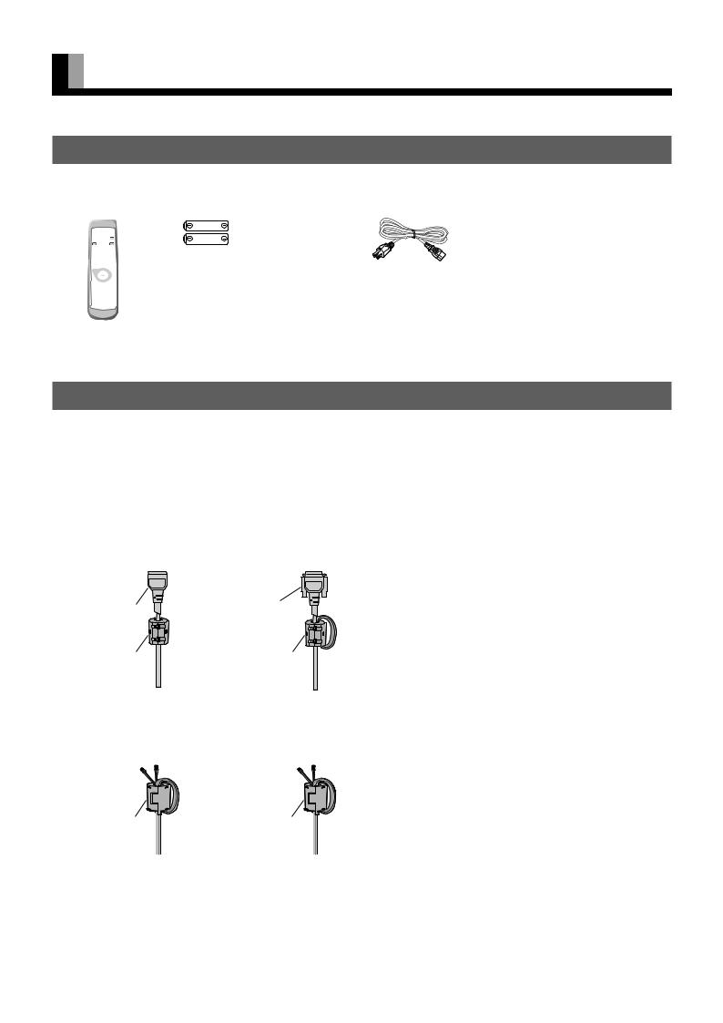
ACCESSORIES
CHECKING ACCESSORIES
One remote control Two AA batteries Two user’s manuals One power cable |
Two big ferrite |
Two small ferrite |
|||||||||||||||||||||
|
|
|
|
|
|
|
|
|
|
|
|
|
|
|
|
|
cores |
|
cores |
||||
|
|
|
|
|
|
|
|
|
|
|
|
|
|
|
|
|
|
|
|
|
|
|
|
|
|
|
|
|
|
|
|
|
|
|
|
|
|
|
|
|
|
|
|
|
|
|
|
|
|
|
|
|
|
|
|
|
|
|
|
|
|
|
|
|
|
|
|
|
|
|
|
|
|
|
|
|
|
|
|
|
|
|
|
|
|
|
|
|
|
|
|
|
|
|
|
|
|
|
|
|
|
|
|
|
|
|
|
|
|
|
|
|
|
|
|
|
|
|
|
|
|
|
|
|
|
|
|
|
|
|
|
|
|
|
|
|
|
|
|
|
|
|
|
(W Type)
(A Type)
CONNECTING THE DISPLAY TO EXTERNAL EQUIPMENT
Carefully check the terminals for position and type before making any connections.
Loose connectors can result in picture or color problems. Make sure that all connectors are securely inserted into their terminals.
Ferrite cores
These ferrite cores are used to attenuate undesired signals.
Two big ferrite cores
When connecting a cable to the power input terminal, RS-232C terminal, attach one of these ferrite cores to the cable near the terminal.
Power Cable |
RS-232C Cable |
Ferrite Core |
Ferrite Core |
Two small ferrite cores
When connecting a cable to the external speaker output terminal attach one of these ferrite cores to the cable near the terminal.
Ferrite Core |
Ferrite Core |
E-2
PART NAMES AND FUNCTIONS
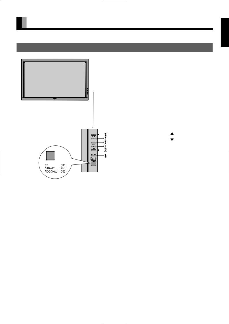
DISPLAY SECTION – FRONT
(Right section)


Control Panel (Right side of display)
1Power indicator lamp
This lamp shows the state of the power supply.
|
Lit (red): |
Stand-by |
|
|
Lit (green): |
Power ON |
|
|
Lit (orange): |
Power saving (DPMS: Power |
|
|
|
saving function) mode ON. |
|
|
|
(Please refer to E-30 of the User's |
|
|
|
Manual(2/2).) |
|
|
Flashing (red or green): Malfunction (Flashes differently |
||
|
|
depending on the type of |
|
|
|
malfunction.) |
|
2 |
Remote control signal receiver |
|
|
|
Receives signals from the remote |
. |
|
3 |
Input mode selector |
[MODE] |
|
4 |
Input mode selector |
[MODE] |
|
|
Switches between picture input modes. |
|
|
5 |
VOL + button |
|
|
6VOL – button
Adjusts the audio volume.
7Wide screen selector button [WIDE]
Switches the screen over to a desired wide screen.
8ON/OFF button
Turns the power “ON” and “OFF (standby state)”.
Warning
If the power indicator lamp flashes red or green, this signifies that the display has developed a problem. When this happens, be sure to remove the power plug from the receptacle and contact your dealer. Leaving the display power ON can result in fire or electric shock.
E-3
English
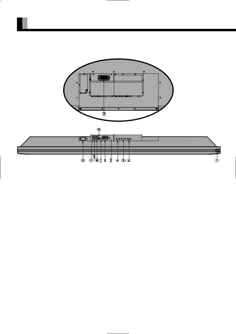
PART NAMES AND FUNCTIONS (Continued)
Back and bottom
Back
Bottom
1 /I power switch
When pressed while in the “OFF” state, the power indicator lamp lights and the display is placed in the “ON  ” state, and the power can be turned “ON” or “OFF” by the remote control or on the control panel of the display. When pressed while in the “ON
  ” state, the power indicator lamp goes out and the display is placed in the “OFF” state where power is still partly supplied.
2RS-232C terminal (RS-232C)
This terminal is provided for you to control the display from the PC. Connect it to the RS-232C terminal on the PC. When connecting a cable, attach a ferrite core to the cable. (See P. E-2.)
3RGB1 input terminal (RGB1 INPUT/DVI-D)
Connect this terminal to the PC’s display (digital RGB) output terminal. *The connection cable No.88741-8000 made by molex Inc. is recommanded.
4RGB2 input terminal (RGB2 INPUT/mD-sub)
Connect this terminal to the PC’s display (analog RGB) output terminal or decoder (digital broadcast tuner, etc.) output terminal.
5 Component video input terminal (VIDEO3 INPUT)
6Component video input terminal (VIDEO4 INPUT)
Connect this terminal to the component video output (color difference output) terminal of your HDTV unit or DVD player.
7Video input terminal (VIDEO1 INPUT)
Connect this terminal to the video output terminal of your VCR.
8S-Video input terminal (VIDEO2 INPUT)
Connect this terminal to the S-video output terminal of your VCR.
9 Audio3 input terminal (AUDIO3 INPUT)
0 Audio2 input terminal (AUDIO2 INPUT)
AAudio1 input terminal (AUDIO1 INPUT)
Connect this terminal to the audio output terminal of your VCR, etc. (See the User’s manual (2/2) for the selection of audio input for video input.)
E-4

English
BExternal speaker output terminal (EXT SP)
Connect this terminal to the optionally available speaker.
When connecting a cable, attach a ferrite core to the cable. (See P. E-2.) *See the speaker instruction manual for more information.
CPower input terminal
Connect this terminal to the power cable supplied with the display. When connecting a cable, attach a ferrite core to the cable. (See P. E-2.)
Description of Input Terminals
DVI-D terminal (RGB1 INPUT/DVI-D)
RGB2 input terminal (RGB2 INPUT/mD-sub)
RS-232C terminal (RS-232C)
Pin No. |
Input signal |
Pin No. |
Input signal |
1 |
Red |
9 |
— |
|
|
|
|
2 |
Green |
10 |
Ground |
|
|
|
|
3 |
Blue |
11 |
— |
|
|
|
|
4 |
— |
12 |
— |
|
|
|
|
5 |
Ground |
13 |
Horizontal synchronization |
|
|
|
|
6 |
Ground |
14 |
Vertical synchronization |
|
|
|
|
7 |
Ground |
15 |
— |
|
|
|
|
8 |
Ground |
Frame |
Ground |
|
|
|
|
|
|
|
|
Pin No. |
Signal |
|
|
|
|
|
|
1DCD (Data Carrier Detect)
2RD (Received Data)
3TD (Transmit Data)
4DTR (Data Terminal ready)
5GND (Ground)
6DSR (Data Set Ready)
7RTS (Request To send)
8CTS (Clear To Send)
9RI (Ring Indication)
* Terminal layout may differ and functions may not be available with some models and some device options.
E-5
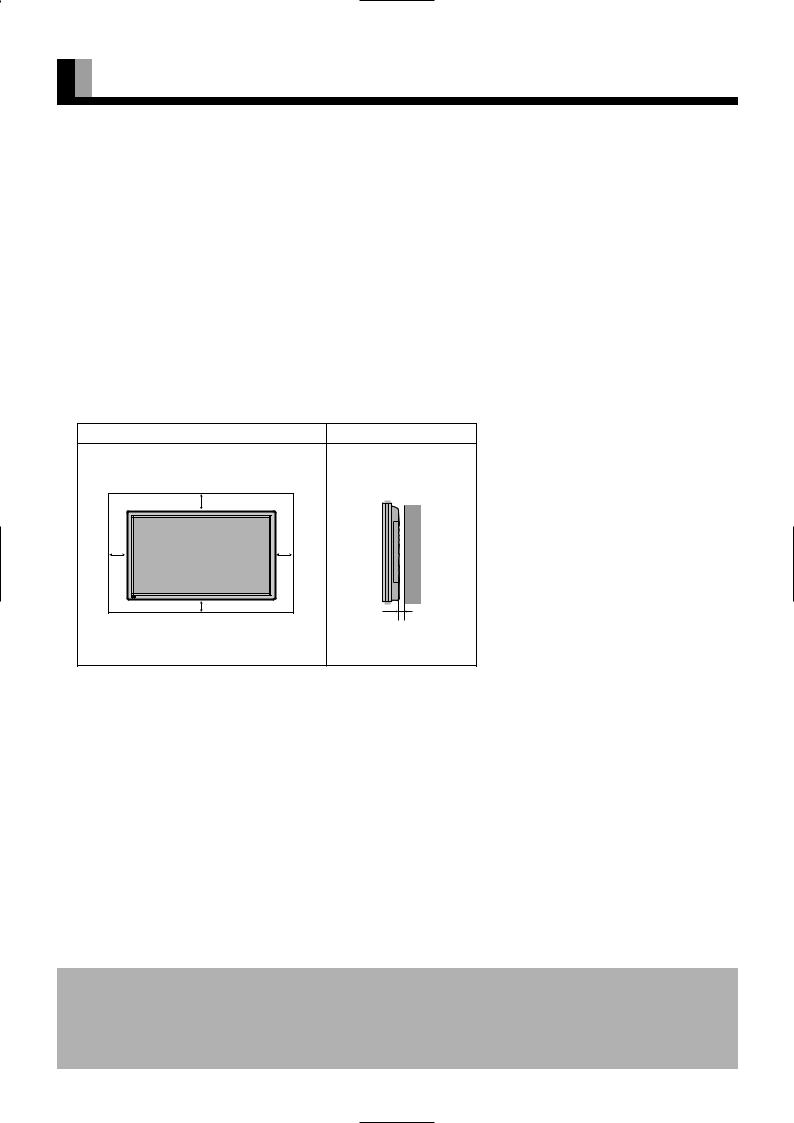
INSTALLATION
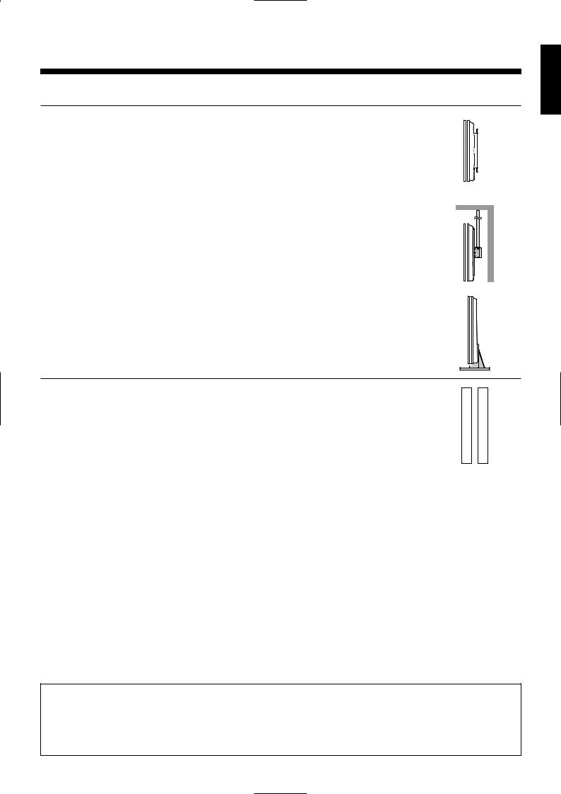
To prevent the display’s internal components from overheating, make sure that the display is installed in a well-ventilated location.
Be sure to use the optional desktop stand, ceiling-mounting unit, wall-mounting unit and other unit when installing this display. Also, be sure that your dealer performs the installation.
See the appropriate instruction manual for more information on the installation hardware you select.
To ensure proper heat radiation, provide at least as much space around the display as shown below.
*Make sure that the display is installed in a location where the temperature can be maintained between 0°C and 40°C.
*Install this device in a well-ventilated area. Keep the air vents of the device free from obstruction.
*Never attempt to tilt the display sideways or backward.
*To prevent the power and other cables from being accidentally pulled, be sure to make the wiring work along the wall or through the corners of floor.
*To prevent an accident and ensure safety in the event of an earthquake, fix the display securely into position as described below.
Horizontal type |
|
|
Front |
|
Side |
|
(cm) |
(cm) |
Upper |
|
|
10 |
|
|
10 |
10 |
|
Left |
Right |
Wall |
|
|
|
5 |
|
|
Lower |
|
5 (for 63”/55”) |
|
|
|
|
|
3.5 (for 50”/42”) |
Note
The display is a highly precise piece of equipment and therefore must be packed properly before transportation. Be sure to use only those packing materials originally supplied with the display when repacking it.
Reference
See P.E-7 for more information on options.
E-6
 OPTIONS
Wall-mounting Bracket |
0° to 15° mounting angle |
P-WB6300 (for 63”/55”) |
|
|
|||
|
|
P-WB4201 (for 50”/42”) |
|
|
|
|
|
|
|
|
|
|
|
|
|
|
|
|
|
|
|
|
|
|
|
|
|
|
|
|
|
|
|
|
|
|
|
|
|
|
|
|
|
|
|
|
|
|
|
|
|
|
|
|
|
|
|
|
|
|
|
|
|
|
|
|
|
|
|
|
|
Ceiling-mounting unit |
0° to 15° mounting angle |
P-CT6300 (for 63”/55”) |
|
|
|||
|
|
P-CT4200 (for 50”/42”) |
|
|
|
|
|
|
|
|
|
|
|
|
|
|
|
|
|
|
|
|
|
|
|
|
|
|
|
|
|
|
|
|
|
|
|
|
|
|
|
|
|
|
|
|
|
|
|
|
|
|
|
|
|
Desktop Stand unit |
P-TT6300 (for 63”/55”) |
|
P-TT4200 (for 50”/42”) |
Speaker |
P-SP6300 (for 63”/55”) |
|
|
|
|
|
P-SP5000 (for 50”) |
|
|
|
|
|
P-SP4200 (for 42”) |
|
|
|
|
|
(1 set of 2 speakers) |
|
|
|
|
|
|
|
|
|
|
|
|
|
|
|
|
English
*When installing an option, make sure that all installation requirements for that option (as given in the relevant instruction manual) are met.
*The colors of options do not match the display colors perfectly.
*To improve the function and performance of optional accessories, specifications and part names may change. Consult your local dealer before purchasing.
Warning
To prevent injury, fire, and electric shock, arrange for options to be initially installed (or installed at a different location) by your dealer.
CAUTION: This display (P63XHA30, P55XHA30) is for use only with Fujitsu General Limited’s option (P- WB6300, P-CT6300, P-TT6300).
This display (P50XHA30, P42HHA30, P42VHA30, P42VHA31) is for use only with Fujitsu General Limited’s option (P-WB4201, P-CT4200, P-TT4200).
Using this display with other option can cause instability resulting in possible injury.
E-7

MAIN SUPPORTED SIGNALS
This display can store the latest four types of signals for RGB adjustment value. The fifth input signal will replace the adjustment value of the first input signal.
To do this, select a desired signal and follow the instructions in “Adjusting Screen Position and Size” on the User’s manual (2/2) to adjust the parameters. When you finish, the settings will be automatically stored. Thus, when the display receives that signal, pictures will be displayed in accordance with the settings you most recently selected.
Main corresponding signals (RGB mode)
Display (dots x lines) |
Horizontal frequency (kHz) |
Vertical frequency (Hz) |
Signal |
DVI-D |
|
|
|
|
|
640 x 480 |
31.47 |
59.94 |
VGA |
|
|
|
|
|
|
640 x 480 |
37.50 |
75.00 |
VGA 75 Hz |
|
|
|
|
|
|
640 x 480 |
43.27 |
85.01 |
VGA 85 Hz |
|
|
|
|
|
|
720 x 400 |
31.47 |
70.09 |
400 lines |
|
|
|
|
|
|
800 x 600 |
37.88 |
60.32 |
SVGA 60 Hz |
|
|
|
|
|
|
800 x 600 |
46.88 |
75.00 |
SVGA 75 Hz |
|
|
|
|
|
|
800 x 600 |
53.67 |
85.06 |
SVGA 85 Hz |
|
|
|
|
|
|
1024 x 768 |
48.36 |
60.00 |
XGA 60 Hz |
|
|
|
|
|
|
1024 x 768 |
60.02 |
75.03 |
XGA 75 Hz |
|
|
|
|
|
|
1024 x 768 |
68.68 |
84.99 |
XGA 85 Hz |
|
|
|
|
|
|
1280 x 1024 |
63.98 |
60.02 |
SXGA 60 Hz |
|
|
|
|
|
|
1280 x 1024 |
79.98 |
75.03 |
SXGA 75 Hz |
|
|
|
|
|
|
848 x 480 |
31.02 |
60.00 |
|
|
|
|
|
|
|
852 x 480 |
31.72 |
59.97 |
|
|
|
|
|
|
|
1360 x 768 |
47.71 |
60.01 |
|
|
|
|
|
|
|
720 x 485 |
15.73 |
59.94 |
60 fields |
|
|
|
|
|
|
720 x 575 |
15.63 |
50.00 |
50 fields |
|
|
|
|
|
|
*With some input signals, “Out of range” may appear even when the horizontal and vertical frequencies are within their permissible ranges. In this event, match the input signals to another frequency rather than those listed above.
*In the DVI-D mode, the input signal can be restricted partly.
It doesn’t support the model with 42” display.
In the Comp.video and Video/S-video modes, the display has been factory-set as follows for different input signals:
Main corresponding signals (Comp.video mode)
Horizontal |
Vertical |
Signal |
|
frequency (kHz) |
frequency (Hz) |
||
|
|||
|
|
|
|
15.73 |
59.94 |
SDTV 480I |
|
|
|
|
|
15.63 |
50.00 |
SDTV 576I |
|
|
|
|
|
31.47 |
59.94 |
SDTV 480P |
|
|
|
|
|
31.25 |
50.00 |
SDTV 576P |
|
|
|
|
|
45.00 |
60.00 |
HDTV 720P |
|
|
|
|
|
37.50 |
50.00 |
HDTV 720P |
|
|
|
|
|
33.75 |
60.00 |
HDTV 1080I |
|
|
|
|
|
28.13 |
50.00 |
HDTV 1080I |
|
|
|
|
Main corresponding signals (Video, S-video mode)
Horizontal |
Vertical |
Signal |
|
frequency (kHz) |
frequency (Hz) |
||
|
|||
|
|
|
|
15.73 |
59.94 |
NTSC |
|
|
|
|
|
15.63 |
50.00 |
PAL |
|
|
|
|
|
15.63 |
50.00 |
SECAM |
|
|
|
|
|
15.63 |
59.52 |
PAL60 |
|
|
|
|
|
15.63 |
50.00 |
N-PAL |
|
|
|
|
|
15.73 |
59.95 |
M-PAL |
|
|
|
|
|
15.73 |
59.94 |
4.43NTSC |
|
|
|
|
•Depending on the input signal, the display may show pictures of reduced size due to size reduction and interpolation.
•“Out of range” appears if the display receives a signal whose characteristic does not fall within the display’s permissible range.
•You can check input signals through “Information” on the FEATURES Menu screen. (See User’s Manual (2/2))
•In order to facilitate the explanations, pictures and diagrams in this manual may differ slightly from the actual items.
•All terms (i.e., company and product names) used in this document are trademarks or registered trademarks.
•Function may be different or unavailable with some models and some device options.
E-8

SPECIFICATION
|
|
|
|
|
|
|
|
|
|
Model |
|
P63XHA30W/A |
|
|
|
|
|
|
|
Screen size |
63" wide screen: |
|
|
|
|
139.3 cm (W) x 78.3 cm (H) (159.8 cm diagonal) |
|
|
|
|
54.8 inch (W) x 30.8 inch (H) (62.9 inch diagonal) |
|
|
|
|
|
|
|
|
Aspect ratio |
16:9 (wide) |
|
|
|
|
|
|
|
|
Weight |
72 kg / 159 lbs |
|
|
|
|
|
|
|
|
Outer dimensions |
150.6 (W) x 89.6 (H) x 12.3 (D) cm |
|
|
|
|
59.3 (W) x 35.3 (H) x 4.8 (D) inch |
(does not include outer projections) |
|
|
|
|
|
|
|
Power supply |
110–240 VAC 50/60 Hz |
|
|
|
|
|
|
|
|
Current rating |
7.9–3.0 A |
|
|
|
|
|
|
|
|
Number of pixels |
1366 (H) x 768 (V) |
|
|
|
|
|
|
|
|
External equipment terminals |
|
|
|
|
|
|
|
|
|
Video input terminals |
VIDEO1 INPUT (Video input) |
1 RCA terminal |
1 Vp-p/75 Ω |
|
|
|
|
|
|
|
VIDEO2 INPUT (S-video input) |
1 S terminal |
Y: |
1 Vp-p/75 Ω |
|
|
|
C: |
0.286 Vp-p/75 Ω |
|
|
|
|
|
|
VIDEO3/VIDEO4 INPUT |
3 RCA terminals |
Y: |
1 Vp-p/75 Ω |
|
(Component video input) |
|
PB/CB: |
0.7 Vp-p/75 Ω |
|
|
|
PR/CR: |
0.7 Vp-p/75 Ω |
– – – – – – – – – – – – – – – – – – – – – – – – – – – – – – – – – – – – – – – – – – – – – – – – – – – – – – – – – – – – – – – – – – – – – – – – – – – – – – – – – – – – – – – – – – – – – – – – – – – – – – – – – – – – – – – – – – – – – – – – – – – – – – – – – – – – – – –
|
Applicable systems |
NTSC/PAL/SECAM/PAL60/N-PAL/M-PAL/4.43NTSC |
||
|
|
|
|
|
|
PC input terminal |
RGB1 input |
1 DVI-D terminal (EIA/CEA-861B Compliant) |
|
|
|
|
RGB2 input |
mD-sub, 3 rows, 15-pin |
|
|
|
|
Picture signal: 0.7 Vp-p/75 Ω |
|
|
|
|
Synchronization signal:TTL level |
|
|
|
||
|
Audio terminals |
2 audio input pin jacks (L/R) (3 lines) |
||
|
|
|
500 mVrms/at least 22 kΩ |
|
|
|
|
||
|
Control terminal |
1 RS-232C connector (D-sub 9-pin) |
||
|
|
|||
|
External speaker output terminal Effective max. output: 10 W + 10 W (EIAJ), 6 Ω |
|||
|
|
|||
Operating conditions |
Temperature: 0 to 40 °C / 32 to 104 °F |
|||
|
|
|
Humidity: |
20 to 80 % |
|
|
|||
Accessories |
1 remote control, 2AA batteries, 2 user’s manuals, 1 power cable, 2 big ferrite cores, |
|||
|
|
|
2 small ferrite cores |
|
|
|
|
||
Regulation |
|
|
||
• UL, CSA Safety: UL6500, C-UL |
|
|||
|
|
EMC: FCC Part 15 Class B, ICES-003 Class B |
||
• CE |
Safety: EN60065 |
|
|
|
|
|
EMC: EN55022 |
1998, Class B |
|
|
|
EN61000-3-2 1995 |
|
|
|
|
EN61000-3-3 1995 |
|
|
|
|
EN55024 |
1998 |
|
|
|
EN61000-4-2 1995 |
|
|
|
|
EN61000-4-3 1996 |
|
|
|
|
EN61000-4-4 1995 |
|
|
|
|
EN61000-4-5 1995 |
|
|
|
|
EN61000-4-6 1996 |
|
|
|
|
EN61000-4-8 1993 |
|
|
|
|
EN61000-4-11 1994 |
|
|
• AS |
Safety: IEC60065 |
|
|
|
|
|
EMC: AS/NZS 3548 |
|
|
English
•Viewing the screen constantly for extended periods can strain your eyes. Be sure to stay at a proper distance (at least 2.4 m or 7.9 feet for 63”) from the screen and to look occasionally away while working.
E-9

SPECIFICATION (Continued)
|
|
|
|
|
|
|
|
|
|
|
|
Model |
|
P55XHA30W/A |
|
|
|
|
|
|
|
|
|
Screen size |
55" wide screen: |
|
|
|
|
|
122.9 cm (W) x 69.1 cm (H) (140.0 cm diagonal) |
|
|
|
|
|
48.4 inch (W) x 27.2 inch (H) (55.1 inch diagonal) |
|
|
|
|
|
|
|
|
|
|
Aspect ratio |
16:9 (wide) |
|
|
|
|
|
|
|
|
|
|
Weight |
55 kg / 121 lbs |
|
|
|
|
|
|
|
|
|
|
Outer dimensions |
137.8 (W) x 81.0 (H) x 12.3 (D) cm |
|
|
|
|
|
54.3 (W) x 31.9 (H) x 4.8 (D) inch |
(does not include outer projections) |
|
|
|
|
|
|
|
|
|
Power supply |
110–240 VAC 50/60 Hz |
|
|
|
|
|
|
|
|
|
|
Current rating |
5.9–2.5 A |
|
|
|
|
|
|
|
|
|
|
Number of pixels |
1366 (H) x 768 (V) |
|
|
|
|
|
|
|
|
|
|
External equipment terminals |
|
|
|
|
|
|
|
|
|
|
|
Video input terminals |
VIDEO1 INPUT (Video input) |
1 RCA terminal |
1 Vp-p/75 Ω |
||
|
|
|
|
|
|
|
VIDEO2 INPUT (S-video input) |
1 S terminal |
Y: |
1 Vp-p/75 Ω |
|
|
|
|
C: |
0.286 Vp-p/75 Ω |
|
|
|
|
|
|
|
|
VIDEO3/VIDEO4 INPUT |
3 RCA terminals |
Y: |
1 Vp-p/75 Ω |
|
|
(Component video input) |
|
PB/CB: |
0.7 Vp-p/75 Ω |
|
|
|
|
PR/CR: |
0.7 Vp-p/75 Ω |
|
– – – – – – – – – – – – – – – – – – – – – – – – – – – – – – – – – – – – – – – – – – – – – – – – – – – – – – – – – – – – – – – – – – – – – – – – – – – – – – – – – – – – – – – – – – – – – – – – – – – – – – – – – – – – – – – – – – – – – – – – – – – – – – – – – – – – – – –
|
Applicable systems |
NTSC/PAL/SECAM/PAL60/N-PAL/M-PAL/4.43NTSC |
||
|
PC input terminal |
RGB1 input |
1 DVI-D terminal (EIA/CEA-861B Compliant) |
|
|
|
|
RGB2 input |
mD-sub, 3 rows, 15-pin |
|
|
|
|
Picture signal: 0.7 Vp-p/75 Ω |
|
|
|
|
Synchronization signal:TTL level |
|
|
|
||
|
Audio terminals |
2 audio input pin jacks (L/R) (3 lines) |
||
|
|
|
500 mVrms/at least 22 kΩ |
|
|
Control terminal |
1 RS-232C connector (D-sub 9-pin) |
||
|
|
|||
|
External speaker output terminal Effective max. output: 10 W + 10 W (EIAJ), 6 Ω |
|||
|
|
|||
Operating conditions |
Temperature: 0 to 40 °C / 32 to 104 °F |
|||
|
|
|
Humidity: |
20 to 80 % |
|
|
|||
Accessories |
1 remote control, 2AA batteries, 2 user’s manuals, 1 power cable, 2 big ferrite cores, |
|||
|
|
|
2 small ferrite cores |
|
|
|
|
||
Regulation |
|
|
||
• UL, CSA Safety: UL6500, C-UL |
|
|||
|
|
EMC: FCC Part 15 Class B, ICES-003 Class B |
||
• CE |
Safety: EN60065 |
|
|
|
|
|
EMC: EN55022 |
1998, Class B |
|
|
|
EN61000-3-2 1995 |
|
|
|
|
EN61000-3-3 1995 |
|
|
|
|
EN55024 |
1998 |
|
|
|
EN61000-4-2 1995 |
|
|
|
|
EN61000-4-3 1996 |
|
|
|
|
EN61000-4-4 1995 |
|
|
|
|
EN61000-4-5 1995 |
|
|
|
|
EN61000-4-6 1996 |
|
|
|
|
EN61000-4-8 1993 |
|
|
|
|
EN61000-4-11 1994 |
|
|
• AS |
Safety: IEC60065 |
|
|
|
|
|
EMC: AS/NZS 3548 |
|
|
•Viewing the screen constantly for extended periods can strain your eyes. Be sure to stay at a proper distance (at least 2.1 m or 6.9 feet for 55”) from the screen and to look occasionally away while working.
E-10
English
Model |
|
P50XHA30W/A |
|
|
|
|
|
|
|
Screen size |
50" wide screen: |
|
|
|
|
110.6 cm (W) x 62.2 cm (H) (126.9 cm diagonal) |
|
|
|
|
43.5 inch (W) x 24.5 inch (H) (50 inch diagonal) |
|
|
|
|
|
|
|
|
Aspect ratio |
16:9 (wide) |
|
|
|
|
|
|
|
|
Weight |
45 kg / 99 lbs |
|
|
|
|
|
|
|
|
Outer dimensions |
121.4 (W) x 72.8 (H) x 9.8 (D) cm |
|
|
|
|
47.8 (W) x 28.7 (H) x 3.9 (D) inch |
(does not include outer projections) |
|
|
|
|
|
|
|
Power supply |
110–240 VAC 50/60 Hz |
|
|
|
|
|
|
|
|
Current rating |
5.2–2.1 A |
|
|
|
|
|
|
|
|
Number of pixels |
1366 (H) x 768 (V) |
|
|
|
|
|
|
|
|
External equipment terminals |
|
|
|
|
|
|
|
|
|
Video input terminals |
VIDEO1 INPUT (Video input) |
1 RCA terminal |
1 Vp-p/75 Ω |
|
|
|
|
|
|
|
VIDEO2 INPUT (S-video input) |
1 S terminal |
Y: |
1 Vp-p/75 Ω |
|
|
|
C: |
0.286 Vp-p/75 Ω |
|
|
|
|
|
|
VIDEO3/VIDEO4 INPUT |
3 RCA terminals |
Y: |
1 Vp-p/75 Ω |
|
(Component video input) |
|
PB/CB: |
0.7 Vp-p/75 Ω |
|
|
|
PR/CR: |
0.7 Vp-p/75 Ω |
– – – – – – – – – – – – – – – – – – – – – – – – – – – – – – – – – – – – – – – – – – – – – – – – – – – – – – – – – – – – – – – – – – – – – – – – – – – – – – – – – – – – – – – – – – – – – – – – – – – – – – – – – – – – – – – – – – – – – – – – – – – – – – – – – – – – – – –
|
Applicable systems |
NTSC/PAL/SECAM/PAL60/N-PAL/M-PAL/4.43NTSC |
||
|
|
|
|
|
|
PC input terminal |
RGB1 input |
1 DVI-D terminal (EIA/CEA-861B Compliant) |
|
|
|
|
RGB2 input |
mD-sub, 3 rows, 15-pin |
|
|
|
|
Picture signal: 0.7 Vp-p/75 Ω |
|
|
|
|
Synchronization signal:TTL level |
|
|
|
||
|
Audio terminals |
2 audio input pin jacks (L/R) (3 lines) |
||
|
|
|
500 mVrms/at least 22 kΩ |
|
|
|
|
||
|
Control terminal |
1 RS-232C connector (D-sub 9-pin) |
||
|
|
|||
|
External speaker output terminal Effective max. output: 10 W + 10 W (EIAJ), 6 Ω |
|||
|
|
|||
Operating conditions |
Temperature: 0 to 40 °C / 32 to 104 °F |
|||
|
|
|
Humidity: |
20 to 80 % |
|
|
|||
Accessories |
1 remote control, 2AA batteries, 2 user’s manuals, 1 power cable, 2 big ferrite cores, |
|||
|
|
|
2 small ferrite cores |
|
|
|
|
||
Regulation |
|
|
||
• UL, CSA Safety: UL6500, C-UL |
|
|||
|
|
EMC: FCC Part 15 Class B, ICES-003 Class B |
||
• CE |
Safety: EN60065 |
|
|
|
|
|
EMC: EN55022 |
1998, Class B |
|
|
|
EN61000-3-2 1995 |
|
|
|
|
EN61000-3-3 1995 |
|
|
|
|
EN55024 |
1998 |
|
|
|
EN61000-4-2 1995 |
|
|
|
|
EN61000-4-3 1996 |
|
|
|
|
EN61000-4-4 1995 |
|
|
|
|
EN61000-4-5 1995 |
|
|
|
|
EN61000-4-6 1996 |
|
|
|
|
EN61000-4-8 1993 |
|
|
|
|
EN61000-4-11 1994 |
|
|
• AS |
Safety: IEC60065 |
|
|
|
|
|
EMC: AS/NZS 3548 |
|
|
•Viewing the screen constantly for extended periods can strain your eyes. Be sure to stay at a proper distance (at least 1.9 m or 6.2 feet for 50”) from the screen and to look occasionally away while working.
E-11

SPECIFICATION (Continued)
|
|
|
|
|
|
|
|
|
|
|
|
|
|
Model |
P42VHA30W/A |
|
P42VHA31W/A |
P42HHA30W/A |
||
|
|
|
|
|
|
|
Screen size |
42" wide screen: |
|
42" wide screen: |
|
|
|
|
92.1 cm (W) x 51.8 cm (H) (105.7 cm diagonal) |
92.2 cm (W) x 52.2 cm (H) (106.0 cm diagonal) |
||||
|
36.3 inch (W) x 20.4 inch (H) (41.6 inch diagonal) |
36.3 inch (W) x 20.6 inch (H) (41.7 inch diagonal) |
||||
|
|
|
|
|
|
|
Aspect ratio |
16:9 (wide) |
|
|
|
|
|
|
|
|
|
|
|
|
Weight |
30 kg / 66 lbs |
|
|
|
|
|
|
|
|
|
|
|
|
Outer dimensions |
103.7 (W) x 64.2 (H) x 8.5 (D) cm |
|
|
|
||
|
40.8 (W) x 25.3 (H) x 3.3 (D) inch (does not include outer projections) |
|
||||
|
|
|
|
|
|
|
Power supply |
110–240 VAC 50/60 Hz |
|
|
|
|
|
|
|
|
|
|
|
|
Current rating |
3.5–1.35 A |
|
4.2–1.7 A |
4.0–1.95 A |
|
|
|
|
|
|
|
|
|
Number of pixels |
852 (H) x 480 (V) |
|
1024 (H) x 1024 (V) |
|
||
|
|
|
|
|
|
|
External equipment terminals |
|
|
|
|
|
|
|
|
|
|
|
||
Video input terminals |
VIDEO1 INPUT (Video input) |
1 RCA terminal |
1 Vp-p/75 Ω |
|||
|
|
|
|
|
|
|
|
VIDEO2 INPUT (S-video input) |
1 S terminal |
Y: |
1 Vp-p/75 Ω |
||
|
|
|
|
|
C: |
0.286 Vp-p/75 Ω |
|
|
|
|
|
|
|
|
VIDEO3/VIDEO4 INPUT |
3 RCA terminals |
Y: |
1 Vp-p/75 Ω |
||
|
(Component video input) |
|
|
PB/CB: |
0.7 Vp-p/75 Ω |
|
|
|
|
|
|
PR/CR: |
0.7 Vp-p/75 Ω |
– – – – – – – – – – – – – – – – – – – – – – – – – – – – – – – – – – – – – – – – – – – – – – – – – – – – – – – – – – – – – – – – – – – – – – – – – – – – – – – – – – – – – – – – – – – – – – – – – – – – – – – – – – – – – – – – – – – – – – – – – – – – – – – – – – – – – – –
|
Applicable systems |
NTSC/PAL/SECAM/PAL60/N-PAL/M-PAL/4.43NTSC |
||
|
PC input terminal |
RGB1 input |
1 DVI-D terminal (EIA/CEA-861B Compliant) |
|
|
|
|
RGB2 input |
mD-sub, 3 rows, 15-pin |
|
|
|
|
Picture signal: 0.7 Vp-p/75 Ω |
|
|
|
|
Synchronization signal:TTL level |
|
|
|
||
|
Audio terminals |
2 audio input pin jacks (L/R) (3 lines) |
||
|
|
|
500 mVrms/at least 22 kΩ |
|
|
Control terminal |
1 RS-232C connector (D-sub 9-pin) |
||
|
|
|||
|
External speaker output terminal Effective max. output: 10 W + 10 W (EIAJ), 6 Ω |
|||
|
|
|||
Operating conditions |
Temperature: 0 to 40 °C / 32 to 104 °F |
|||
|
|
|
Humidity: |
20 to 80 % |
|
|
|||
Accessories |
1 remote control, 2AA batteries, 2 user’s manuals, 1 power cable, 2 big ferrite cores, |
|||
|
|
|
2 small ferrite cores |
|
|
|
|
||
Regulation |
|
|
||
• UL, CSA Safety: UL6500, C-UL |
|
|||
|
|
EMC: FCC Part 15 Class B, ICES-003 Class B |
||
• CE |
Safety: EN60065 |
|
|
|
|
|
EMC: EN55022 |
1998, Class B |
|
|
|
EN61000-3-2 1995 |
|
|
|
|
EN61000-3-3 1995 |
|
|
|
|
EN55024 |
1998 |
|
|
|
EN61000-4-2 1995 |
|
|
|
|
EN61000-4-3 1996 |
|
|
|
|
EN61000-4-4 1995 |
|
|
|
|
EN61000-4-5 1995 |
|
|
|
|
EN61000-4-6 1996 |
|
|
|
|
EN61000-4-8 1993 |
|
|
|
|
EN61000-4-11 1994 |
|
|
• AS |
Safety: IEC60065 |
|
|
|
|
|
EMC: AS/NZS 3548 |
|
|
•Specifications and external appearance may be change for the sake of improvement.
•Viewing the screen constantly for extended periods can strain your eyes. Be sure to stay at a proper distance (at least 1.6 m or 5.2 feet for 42”) from the screen and to look occasionally away while working.
•  is a worldwide trademark of Fujitsu General Limited and is a registered trademark in Japan, the U.S.A. and other countries or areas.
E-12
English
USER’S MANUAL (2/2)
(Precautions and Adjustment Methods)
WIDE PLASMA DISPLAY
Contents
Page
Before Use
•Safety Precautions ···························································································· E-2–E-3
Usage
•Handy Tips ·················································································································E-4
• Connecting the Display to External Equipment ·············································· E-5–E-8
•Using the Remote Control ·············································································· E-9–E-11
•Basic Operations ··························································································· E-12–E-13
•Selecting Input Mode ······························································································E-14
•Other Basic Operations ·································································································· E-15
•Watching Pictures on the Wide Screen ······················································· E-16–E-17
Adjustments
•Adjustment Menu ···································································································E-18
• Adjusting Pictures (PICTURE Menu) ···························································· E-19–E-21
•Adjusting Screen Position and Size (POSITION/SIZE Menu) ···················· E-22–E-23
•Adjusting Audio (AUDIO Menu) ·································································· E-24–E-25
•Other Adjustments (FEATURES Menu) ································································E-26–E-32
•Initialization of User Adjustment Value (FACTORY DEFAULT) ····························E-33
•Cleaning and Maintenance ·····················································································E-34
Before using the display, read the User’s manual (1/2) and the User’s manual (2/2) carefully so that you know how to use the display correctly.
Refer to these manuals whenever questions or problems about operation arise. Be sure to read and observe the safety precautions.
Keep these manuals where the user can access them readily.
* Installation and removal require special expertise. Consult your product dealer for details.
 SAFETY PRECAUTIONS
IMPORTANT INFORMATION
IMPORTANT
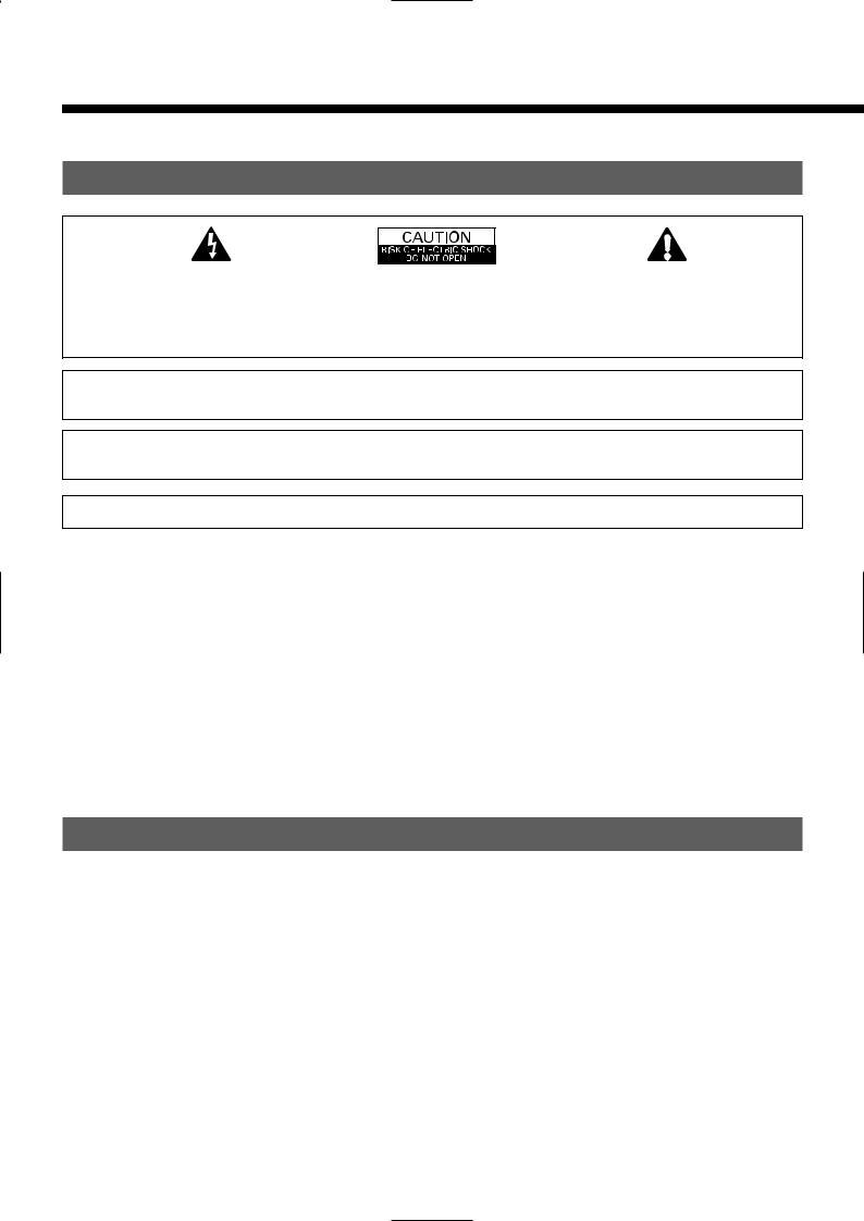
The lightning flash with arrowhead symbol, within an equilateral triangle, is intended to alert the user to the presence of uninsulated “dangerous voltage” within the product’s enclosure that may be of sufficient magnitude to constitute a risk of electric shock to persons.
CAUTION:
TO PREVENT THE RISK OF ELECTRIC SHOCK, DO NOT REMOVE COVER (OR BACK). NO USER-SERVICEABLE PARTS INSIDE. REFER SERVICING TO QUALIFIED SERVICE PERSONNEL.
The exclamation point within an equilateral triangle is intended to alert the user to the presence of important operating and maintenance (servicing) instructions in the literature accompanying the appliance.
WARNING: This is a Class A and Class B product. In a domestic environment this product may cause radio interference in which case the user may be required to take adequate measures.
WARNING: TO REDUCE THE RISK OF FIRE AND ELECTRIC SHOCK, DO NOT EXPOSE THIS PRODUCT TO RAIN OR MOISTURE.
FCC NOTICE
• A Class A digital device
This equipment has been tested and found to comply with the limits for a Class A digital device, pursuant to Part 15 of the FCC Rules. These limits are designed to provide reasonable protection against harmful interference when the equipment is operated in a commercial environment. This equipment generates, uses, and can radiate radio frequency energy and, if not installed and used in accordance with the instruction manual, may cause harmful interference to radio communications. Operation of this equipment in a residential area is likely to cause harmful interference in which case the user will be required to correct the interference at his own expense.
• A Class B digital device
This equipment has been tested and found to comply with the limits for a Class B digital device, pursuant to Part 15 of the FCC Rules. These limits are designed to provide reasonable protection against harmful interference in a residential installation. This equipment generates, uses and can radiate radio frequency energy and, if not installed and used in accordance with the instructions, may cause harmful interference to radio communications. However, there is no guarantee that interference will not occur in a particular installation. If this equipment does cause harmful interference to radio or television reception, which can be determined by turning the equipment off and on, the user is encouraged to try to correct the interference by one or more of the following measures:
–Reorient or relocate the receiving antenna.
–Increase the separation between the equipment and receiver.
–Connect the equipment into an outlet on a circuit different from that to which the receiver is connected.
–Consult the dealer or an experienced radio/TV technician for help.
IMPORTANT SAFETY INSTRUCTIONS
Electrical energy can perform many useful functions. This unit has been engineered and manufactured to assure your personal safety. But
IMPROPER USE CAN RESULT IN POTENTIAL ELECTRICAL SHOCK OR FIRE HAZARD. In order not to defeat the safeguards incorporated into this product, observe the following basic rules for its installation, use and service. Please read these “Important Safeguards” carefully before use.
1)Read these instructions.
2)Keep these instructions.
3)Heed all warnings.
4)Follow all instructions.
5)Do not use this apparatus near water.
6)Clean only with dry cloth.
7)Do not block any ventilation openings. Install in accordance with the manufacturer’s instructions.
8)Do not install near any heat sources such as radiators, heat registers, stoves, or other apparatus (including amplifier’s) that produce heat.
9)Do not defeat the safety purpose of the polarized or grounding-type plug. A polarized plug has two blades with one wider than the other. A grounding type plug has two blades and a third grounding prong. The wide blade or the third prong are provided for your safety. If the provided plug does not fit into your outlet, consult an electrician for replacement of the obsolete outlet.
10)Protect the power cord from being walked on or pinched particularly at plugs, convenience receptacles, and the point where they exit from the apparatus.
11)Only use attachments/accessories specified by the manufacturer.
E-2
Loading...