


MB91460
Table of contents
 Loading...
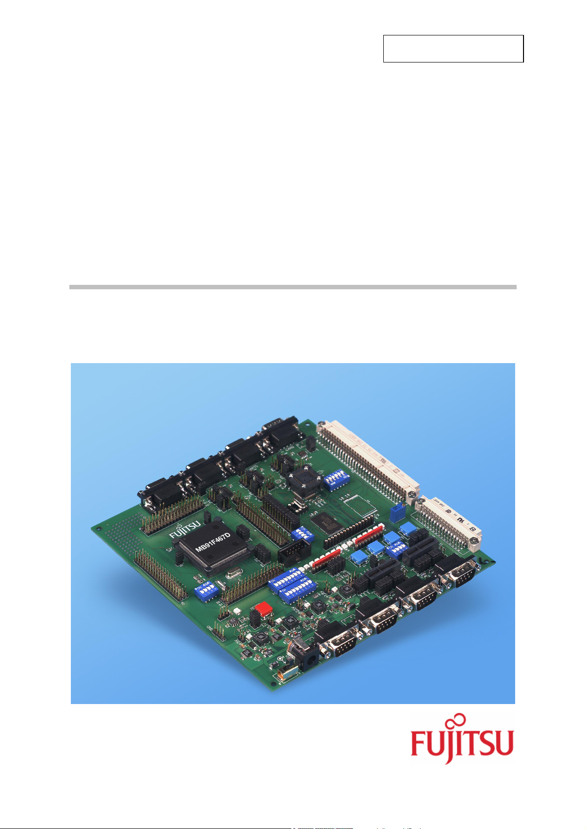
Fujitsu Microelectronics Europe
User Guide
FMEMCU-UG-910017-11
MB88121 SERIES
MB91460 SERIES
STARTER KIT
SK-91F467-FLEXRAY
USER GUIDE

SK-91F467-FLEXRAY V1.1
Revision History
Revision History
Date Issue
22/11/2005
V1.0, MSt,
first official version
V1.1, MSt
01/06/2006
SK-91F467D-208PFV information removed,
Getting started chapter changed to new Monitor debugger version
This document contains 73 pages.
FMEMCU-UG-910017-11 - 2 - © Fujitsu Microelectronics Europe GmbH

SK-91F467-FLEXRAY V1.1
Warranty and Disclaimer
Warranty and Disclaimer
To the maximum extent permitted by applicable law, Fujitsu Microelectronics Europe GmbH restricts
its warranties and its liability for the SK-91F467-FLEXRAY and all its deliverables (eg. software
include or header files, application examples, target boards, evaluation boards, engineering samples
of IC’s etc.), its performance and any consequential damages, on the use of the Product in
accordance with (i) the terms of the License Agreement and the Sale and Purchase Agreement under
which agreements the Product has been delivered, (ii) the technical descriptions and (iii) all
accompanying written materials. In addition, to the maximum extent permitted by applicable law,
ujitsu Microelectronics Europe GmbH disclaims all warranties and liabilities for the performance of
F
the Product and any consequential damages in cases of unauthorised decompiling and/or reverse
engineering and/or disassembling. Note, the SK-91F467-FLEXRAY board and all its deliverables
are intended and must only be used in an evaluation laboratory environment.
1. Fujitsu Microelectronics Europe GmbH warrants that the Product will perform substantially in
accordance with the accompanying written materials for a period of 90 days form the date of
receipt by the customer. Concerning the hardware components of the Product, Fujitsu
Microelectronics Europe GmbH warrants that the Product will be free from defects in material
and workmanship under use and service as specified in the accompanying written materials
for a duration of 1 year from the date of receipt by the customer.
2. Should a Product turn out to be defect, Fujitsu Microelectronics Europe GmbH’s entire liability
and the customer’s exclusive remedy shall be, at Fujitsu Microelectronics Europe GmbH’s
sole discretion, either return of the purchase price and the license fee, or replacement of the
Product or parts thereof, if the Product is returned to Fujitsu Microelectronics Europe GmbH in
original packing and without further defects resulting from the customer’s use or the transport.
However, this warranty is excluded if the defect has resulted from an accident not attributable
to Fujitsu Microelectronics Europe GmbH, or abuse or misapplication attributable to the
customer or any other third party not relating to Fujitsu Microelectronics Europe GmbH.
3. To the maximum extent permitted by applicable law Fujitsu Microelectronics Europe GmbH
disclaims all other warranties, whether expressed or implied, in particular, but not limited to,
warranties of merchantability and fitness for a particular purpose for which the Product is not
designated.
4. To the maximum extent permitted by applicable law, Fujitsu Microelectronics Europe GmbH’s
and its suppliers´ liability is restricted to intention and gross negligence.
NO LIABILITY FOR CONSEQUENTIAL DAMAGES
To the maximum extent permitted by applicable law, in no event shall Fujitsu
Microelectronics Europe GmbH and its suppliers be liable for any damages whatsoever
(including but without limitation, consequential and/or indirect damages for personal
injury, assets of substantial value, loss of profits, interruption of business operation,
loss of information, or any other monetary or pecuniary loss) arising from the use of
the Product.
Should one of the above stipulations be or become invalid and/or unenforceable, the remaining
stipulations shall stay in full effect
© Fujitsu Microelectronics Europe GmbH - 3 - FMEMCU-UG-910017-11

SK-91F467-FLEXRAY V1.1
Contents
Contents
REVISION HISTORY............................................................................................................ 2
WARRANTY AND DISCLAIMER ......................................................................................... 3
CONTENTS .......................................................................................................................... 4
1 INTRODUCTION.............................................................................................................. 7
1.1 Abstract................................................................................................................... 7
1.2 Features.................................................................................................................. 8
1.3 General Description................................................................................................. 9
1.3.1 On Board Memory ................................................................................... 10
1.3.2 MCU Clocks............................................................................................. 10
1.3.3 MCU Operating Mode.............................................................................. 10
1.3.4 FlexRay CC Clock ................................................................................... 10
1.3.5 FlexRay CC-MCU Connection ................................................................. 10
1.3.6 External Bus interface Connectors........................................................... 10
1.3.7 FlexRay Physical Layer ........................................................................... 10
1.3.8 CAN Bus.................................................................................................. 10
1.3.9 RS-232 and LIN....................................................................................... 10
1.3.10 MCU Pins11
1.3.11 User Buttons............................................................................................ 11
1.3.12 User LEDs and optional LCD................................................................... 11
1.3.13 Power Supply .......................................................................................... 11
2 INSTALLATION ............................................................................................................. 12
2.1 Jumper Settings .................................................................................................... 14
2.2 Jumper Location.................................................................................................... 16
2.3 Software Installation.............................................................................................. 17
2.3.1 Installation of Softune Workbench ........................................................... 17
3 JUMPERS AND SWITCHES.......................................................................................... 19
3.1 MCU Operating-Mode (S5).................................................................................... 19
3.2 FlexRay CC Operating-Mode (S2)......................................................................... 20
3.3 FlexRay CC SPI Settings (S1)............................................................................... 21
3.4 Power Supply ........................................................................................................ 22
3.4.1 MCU Power Supply Voltage .................................................................... 24
3.4.2 MCU Analogue Power Supply Voltage..................................................... 24
3.4.3 FlexRay CC Power Supply Voltage at SK-91F467-FLEXRAY.................. 25
3.5 MCU-FlexRay CC Connection at SK-91F467-FLEXRAY....................................... 26
FMEMCU-UG-910017-11 - 4 - © Fujitsu Microelectronics Europe GmbH

SK-91F467-FLEXRAY V1.1
Contents
3.6 FlexRay Physical Layer......................................................................................... 27
3.6.1 Channel A................................................................................................ 27
3.6.2 Channel B................................................................................................ 28
3.6.3 FT1080 Control Settings (S6) .................................................................. 30
3.7 CAN0 – CAN2 ....................................................................................................... 31
3.8 LIN / RS-232 UART............................................................................................... 31
3.8.1 UART 2.................................................................................................... 32
3.8.2 UART 4 (Flash programming).................................................................. 33
3.8.3 UART 5.................................................................................................... 34
3.9 User Push Buttons INT0, INT1, INT2 and ICU0/TIN0............................................ 35
3.10 User DIP Switch 8 Bit (S4) .................................................................................... 35
3.11 Reset Generation .................................................................................................. 36
4 CONNECTORS.............................................................................................................. 38
4.1 Power Connector (X5)........................................................................................... 38
4.2 UART / LIN Connector (X1, X4, X8) ...................................................................... 38
4.3 CAN Connector (X9, X10, X11) ............................................................................. 39
4.4 FlexRay Connector (X2, X6).................................................................................. 39
4.5 FlexRay Physical Layer Module Connector (X3, X7) ............................................. 40
4.6 USER-LEDs and optional LC-Display (D1-D16, J6)............................................... 41
4.7 In-Circuit-Programming Connector (X12) .............................................................. 42
4.8 MCU Pin Connectors (J1-J4)................................................................................. 42
4.9 External Bus Connectors (X13, X14)..................................................................... 43
4.9.1 VG96ABC DIN 41612 (X13) .................................................................... 43
4.9.2 VG48ABC DIN 41612 (X14) .................................................................... 44
4.9.3 Distance between VG-Connectors........................................................... 44
5 GETTING STARTED...................................................................................................... 45
5.1 Introduction to Softune Workbench ....................................................................... 45
5.2 Project Start-up ..................................................................................................... 47
5.2.1 Create a New Project:.............................................................................. 47
5.2.2 Use Active Configuration MONDEBUG_INTERNAL ................................ 49
5.2.3 Use Active configuration STANDALONE ................................................. 51
5.3 Softune Workbench Monitor Debugger.................................................................. 52
5.3.1 General Description................................................................................. 52
5.3.2 Basic Debugger Features ........................................................................ 55
5.4 Advanced Monitor Debugger Features.................................................................. 56
5.5 Memory Configuration for User Applications.......................................................... 59
6 FLASH PROGRAMMING............................................................................................... 61
© Fujitsu Microelectronics Europe GmbH - 5 - FMEMCU-UG-910017-11

SK-91F467-FLEXRAY V1.1
Contents
6.1 Programming internal Flash of MB91F467DA series............................................. 61
7 TROUBLE SHOOTING.................................................................................................. 64
8 SILK-PLOT OF THE BOARD ........................................................................................ 65
8.1 Top Side................................................................................................................ 65
8.2 Bottom Side........................................................................................................... 66
9 PCB HISTORY............................................................................................................... 67
9.1 SK-91F467-FLEXRAY V1.0 .................................................................................. 67
9.2 SK-91F467-FLEXRAY V1.1 .................................................................................. 67
10 APPENDIX..................................................................................................................... 68
10.1 Related Products................................................................................................... 68
10.2 Information on the WWW ...................................................................................... 69
10.3 Tables ................................................................................................................ 70
10.4 Figures ................................................................................................................ 72
10.5 Abbreviations ........................................................................................................ 73
FMEMCU-UG-910017-11 - 6 - © Fujitsu Microelectronics Europe GmbH

SK-91F467-FLEXRAY V1.1
Introduction
1 Introduction
1.1 Abstract
The SK-91F467-FLEXRAY is a multifunctional development board for the FUJITSU FlexRay
communication controller MB88121 and the 32-bit Flash microcontroller MB91F467DA. It
can be used stand alone for software development and testing or together with monitordebugger software.
The board allows the designer immediately to start with the software and system
development, before his own final target system is available.
© Fujitsu Microelectronics Europe GmbH - 7 - FMEMCU-UG-910017-11

SK-91F467-FLEXRAY V1.1
Introduction
1.2 Features
• Supports 32-bit Flash microcontroller MB91F467D
• Supports FlexRay CC MB88121
• 9-12V (2000mA) unregulated external DC power supply
• 5V, 3.3V, 2.5V and 1.8V on-board switching regulators with power status-LEDs
• Triple supply monitor to watch 5V, 3.3V and selectable 2.5V or 1.8V
• On-board Memory:
o 32Mbit (4MByte) SRAM
• It is possible to connect the FlexRay CC in different ways to the MCU
• 16 bit non multiplexed / multiplexed bus
• 8 bit non multiplexed / multiplexed bus
• SPI communication
• All microcontroller resources available for evaluation
• All microcontroller pins routed to pin header
• In-Circuit serial Flash programming
• Three selectable RS-232 or LIN UART-interfaces
• Three High-Speed CAN interfaces
• Two FlexRay channels (Ch-A, Ch-B)
• FlexRay physical layer RS-485 available
• FlexRay physical layer driver module from TZM (FT1080) connectable
• 16 User LEDs
• optional: alphanumeric standard LC-Display connectable
• Reset button, Reset-LED
• 4 User buttons, one 8 bit MCU port can be connected to DIP switches
• External bus interface routed to 96pin and 48pin DIN 41612 (VG) connectors
This board must only be used for test applications
in an evaluation laboratory environment.
FMEMCU-UG-910017-11 - 8 - © Fujitsu Microelectronics Europe GmbH

SK-91F467-FLEXRAY V1.1
Introduction
1.3 General Description
The SK-91F467-FLEXRAY supports the FUJITSU 32-bit Flash microcontroller MB91F467D
and the FUJITSU FlexRay stand alone communication controller MB88121.
The Starter Kit can be used as a stand-alone development platform, or if a MCU socket is
soldered instead of the Flash MCU MB91F467D, with the emulation system MB91V460
adapter board (MB2198-300) and 208 pin probe cable board (PB-91467D-NLS-208PFV).
This User Guide is describing PCB version V1.1. The PCB version is printed at the TOP side
of the starter kit close to MB91F467D MCU [U1].
© Fujitsu Microelectronics Europe GmbH - 9 - FMEMCU-UG-910017-11

SK-91F467-FLEXRAY V1.1
Introduction
1.3.1 On Board Memory
The starter kit includes 32MBit (4MByte) SRAM memory on board. The SRAM can be used
with 5V, or with 3.3V external bus supply voltage.
1.3.2 MCU Clocks
The board is supplied with a 4MHz crystal as the main oscillation clock for the MCU. Using
the internal PLL of the MCU, internal clock rates up to 100MHz can be achieved. The MCU
sub clock is connected to a 32.768 kHz crystal.
1.3.3 MCU Operating Mode
The operating mode of the microcontroller can be selected with the Dip-switch S5.
1.3.4 FlexRay CC Clock
The FlexRay CC clock is operated by a 10MHz crystal mounted in a socket. By removing the
10MHz crystal it is also possible to use an external clock oscillator.
1.3.5 FlexRay CC-MCU Connection
The FlexRay CC (MB88121) is connected to the MCU via external bus. It is possible to use it
in 8 bit / 16 bit multiplexed, 8 bit / 16 bit non multiplexed or SPI communication-mode
(dependent from revision of MB88121). With jumper or switches the user can change
between the different modes.
1.3.6 External Bus interface Connectors
Via DIN 41612 VG96ABC and VG48ABC connectors (external bus interface of the MCU), it
is possible to connect the FlexRay FPGA Board to the Starter Kit and use the FPGA as
FlexRay communication controller. It is also possible to connect other devices e.g. user
applications or Fujitsu graphic device sub boards.
1.3.7 FlexRay Physical Layer
The connection to the physical layer of the FlexRay bus with 9-pin D-Sub connectors (X2
and X6) is realized with RS485 transceiver, or it is also possible to deselect the RS485
transceiver and use pluggable physical layer driver module from TZM (FT1080) instead.
1.3.8 CAN Bus
Three high-speed CAN-transceivers (PCA82C250) are available to connect all available onchip CAN-controllers to 9-pin D-Sub connectors (X9, X10 and X11). The transceivers
provides differential transmit and receive capability between CAN-controller and CAN-bus.
1.3.9 RS-232 and LIN
RS-232 and LIN signals are shared on the 9-pin D-Sub connectors (X1, X4 and X8). It can
be selected, if RS-232 or LIN will be used.
Three separate RS-232 transceivers and three separate LIN transceivers are available, to
connect the on-chip USARTs to the 9-pin D-Sub connectors.
The RS-232 transceivers generate the adequate RS-232 levels for receive (RXD) and
transmit (TXD) lines. The RTS signal can be shortcut to CTS using jumpers (some PC
software needs this connection, when a 1:1 cable is used).
FMEMCU-UG-910017-11 - 10 - © Fujitsu Microelectronics Europe GmbH

SK-91F467-FLEXRAY V1.1
Introduction
Either the DTR line or the RTS line of X1, X4 or X8 connectors can be selected to generate
a system reset.
The LIN transceivers (TLE6259) generate the adequate levels to drive the bus line in LINsystems for automotive and industrial applications.
1.3.10 MCU Pins
All 208 pins of the microcontroller are connected to the edge connectors J1, J2, J3 and J4
and are directly available to the user.
1.3.11 User Buttons
There are four push buttons on board, which can be connected to input-ports of the
microcontroller. Some ports may support additional functions like external interrupts (INT0,
INT1 and INT2) and trigger for the Reload Timer or Input-Capture (TIN0 / ICU0). One
additional button is reserved as System-Reset-button to reset the MCU and the FLEXRAY
CC simultaneously, but it is possible to disconnect the RST-ports with JP52 or JP54.
It is possible to connect with Dip-switch S3 eight port input switches at S4 to the MCU port
P26_D0 – P26_D7. All eight ports can be switched separately to use e.g. only four ports as
input.
1.3.12 User LEDs and optional LCD
Sixteen user-LEDs are connected via two pull-down resistor networks to port P25_D0 P25_D7 and to port P16_D0 - P16_D7. Parallel to the LEDs on port P25, the connector J6
can be used to connect a standard alphanumeric display. The resistor networks RN2 and
RN3 can be removed, to free the ports.
1.3.13 Power Supply
The four on-board step-down switching regulators allow the user to connect an unregulated
DC input voltage between +9V to +12V (max. 2000mA) to the starter-kit. The switching
regulators provide the voltages of 5V (3A), 3.3V (3A), 2.5V (1,5A) and 1.8V (1,5A) on the
starter kit. These voltages give also the possibility, to connect an optional graphic-controller
starter kit to the board. The switching regulators are short circuit protected and provide a
thermal shutdown.
If the SK-91F467-FLEXRAY starter-kit is connected to the Fujitsu FlexRay FPGA-board it is
possible, that the power supply for the SK-91F467-FLEXRAY will be provided by the FPGAboard and a power supply connection to the SK-91F467-FLEXRAY is not needed. For that
case the pins 14B, 15B and 16B of DIN 41612 VG48ABC connector X14 are used as
voltage input behind the SK-91F467-FLEXRAY on-board power switch, so that the power
switch on the FPGA board switches the whole system.
© Fujitsu Microelectronics Europe GmbH - 11 - FMEMCU-UG-910017-11
SK-91F467-FLEXRAY V1.1
Installation
2 Installation
Remove the board carefully from the shipping carton.
First check if there are any damages before power on the starter kit.
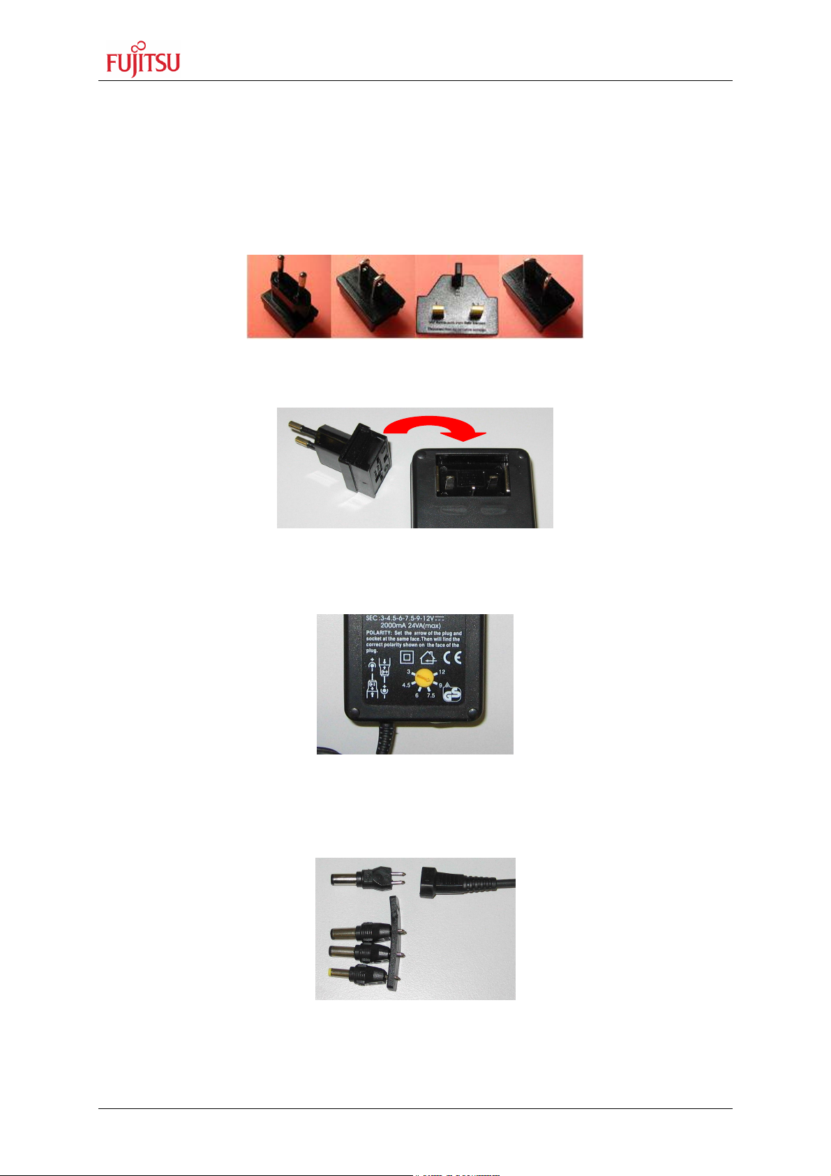
To supply the starter kit, use the delivered In-Plug AC-DC Adapter (UPA 2000). Select the
AC plug adapter suitable for your country power sockets
Figure 2-1: AC plug adapter
and insert this adapter into the connection terminal on the AC-DC adapter.
Figure 2-2: AC plug adapter selection
Check the selected output DC voltage of the AC-DC In-Plug adapter at the voltage selection
key. It should be 9V! Change the output voltage only in a powered-down condition!
Figure 2-3: DC voltage selection
Select the low voltage adapter suitable to the power connector X5 at the SK-91F467FLEXRAY and plug it to the connecting socket in the right orientation (+ connected to shield
and GND connected to centre pin).
Figure 2-4: Low voltage adapter selection
Now connect the DC low voltage adapter to the Starter kit and plug in the In-Plug Power
Supply to a power socket. The SK-91F467-FLEXRAY can be turned on with the on board
power switch S8 (or S9).
FMEMCU-UG-910017-11 - 12 - © Fujitsu Microelectronics Europe GmbH
SK-91F467-FLEXRAY V1.1
Installation
For the power supply of the SK-91F467-FLEXRAY a DC input voltage of 9V – 12V is
recommended. The positive voltage (+) must be connected to the shield, and ground
(GND) must be connected to the centre of the connector X5!
After power-on of the SK-91F467-FLEXRAY, the four red power-on LEDs D24 (5V), D30
(3.3V), D34 (2.5V) and D40 (1.8V) should be light. The reset LED D18 should be off.
Additionally the LED D2 and D4 should be on. The starter kit is delivered with programmed
Softune Workbench Monitor Debugger in internal Flash of MB91F467D series. The monitor
debugger is checking also the external SRAM access at CS1. In case of successful access
to external SRAM the LED D2 and D4 are ON. In case of failed access LED D1 and D4 are
set to ON.
Figure 2-5: Starter kit status after power on
© Fujitsu Microelectronics Europe GmbH - 13 - FMEMCU-UG-910017-11

SK-91F467-FLEXRAY V1.1
Installation
2.1 Jumper Settings
The following table lists all jumpers including its default setting and location on the starter kit.
The default jumper setting is described for 16 bit non multiplexed bus communication
between MCU and FlexRay CC.
Jumper Description / Function Type Default
JP1 ASSP A10 / INT2 Jumper 3 pin 1-2 G 7 1 / 3
JP2 ASSP A9 / INT3 Jumper 3 pin 1-2 G 7 1 / 3
JP3 ASSP A5 / SCK Jumper 3 pin 1-2 G 8 1 / 3
JP4 ASSP A4 / SDI Jumper 3 pin 1-2 G 8 1 / 3
JP5 ASSP A3 / SDO Jumper 3 pin 1-2 G 8 1 / 3
JP6 ASSP BCLK – MCU MCLKI Solder Jumper 2 pad Closed K 9 1 / 3
JP7 ASSP – MCU A0 connection Jumper 2 pin Closed B 8 1 / 3
JP8 ASSPVcc 5V / 3.3V Solder Jumper 3 pad 1-2 J 6 1 / 3
JP9 ASSPVcc1 ASSPVcc / 3.3V Solder Jumper 3 pad 1-2 J 6 1 / 3
JP10 ASSP D10 / MDS2 Jumper 3 pin 1-2 G 8 1 / 3
JP11 ASSP D9 / MDS1 Jumper 3 pin 1-2 G 9 1 / 3
JP12 ASSP D8 / MDS0 Jumper 3 pin 1-2 G 9 1 / 3
JP13 ASSP C-Pin – 1.8V Solder Jumper 2 pad Closed K 8 1 / 3
JP14 ASSP D5 / INT2 Jumper 3 pin 1-2 G 9 1 / 3
JP15 MCUVcc - AVcc Jumper 2 pin Closed E 9 1 / 3
JP16 AVcc - AVRH Jumper 2 pin Closed E 9 1 / 3
JP17 ASSP D4 / INT3 Jumper 3 pin 1-2 G 10 1 / 3
JP18 GND - AVss Jumper 2 pin Closed E 8 1 / 3
JP19 ASSP CS CSX3 / CSX6 Jumper 3 pin 1-2 G 10 1 / 3
JP20 ASSP ALE / INT2 Jumper 3 pin 1-2 G 10 1 / 3
JP21 VDD35 MCUVcc / 3.3V Solder Jumper 3 pad 1-2 F 15 1 / 3
JP22 ASSP BGT – 1.8V Solder Jumper 2 pad Closed J 9 1 / 3
JP23 MCUVcc – HVDD5 Jumper 2 pin Closed E 10 1 / 3
JP24 ASSP MT - GND Solder Jumper 2 pad Closed K 9 1 / 3
JP25 MCUVcc – VDD5R Jumper 2 pin Closed E 11 1 / 3
JP26 Vcc - MCUVcc Jumper 2 pin Closed E 11 1 / 3
JP27 MCUVcc – VDD5 Jumper 2 pin Closed E 11 1 / 3
JP28 GND – HVSS5 Jumper 2 pin Closed E 6 1 / 3
JP29 DTR select DTR / /DTR Jumper 3 pin Open B 14 2 / 3
JP30 UART2 RTS - CTS Jumper 2 pin Open D 3 2 / 3
JP31 FlexRay nSTB – P18_6 Jumper 2 pin Open G 16 2 / 3
JP32 FlexRay WAKE – P18_5 Jumper 2 pin Open G 16 2 / 3
JP33 FlexRay EN – P18_4 Jumper 2 pin Open G 16 2 / 3
JP34 FlexRay CHA RS485 Termination Jumper 2 pin Closed H 18 2 / 3
JP35 FlexRay RxD_A Jumper 2 pin Closed J 18 2 / 3
JP36 FlexRay CHA RS485 Termination Jumper 2 pin Closed H 18 2 / 3
JP37 UART2 RxD RS232 / LIN Jumper 3 pin 2-3 F 5 2 / 3
JP38
JP39
JP40
JP41
JP42
JP43
JP44
JP45
JP46
JP47
JP48
JP49
JP50
JP51
JP52
JP53 VccPL 5V / 3.3V
JP54 RESET - MCU RST
FlexRay CHA RS485 - BM
UART2 DTR / RTS
FlexRay TxEN_A
FlexRay CHA RS485 - BP
Watch 1.8V
Watch 2.5V
UART2 TxD RS232 / LIN
FlexRay TxD_A
UART2 RS232 / LIN
UART2 LIN Enable
FlexRay CHA EN
FlexRay CHA WAKE
FlexRay CHA nSTB
UART2 LIN Master Yes / No
RESET - ASSP RST
Jumper 2 pin Closed
Jumper 3 pin Open F 4 2 / 3
Jumper 2 pin Closed J 18 2 / 3
Jumper 2 pin Closed
Solder Jumper 2 pad Open
Solder Jumper 2 pad Closed B 15 2 / 3
Jumper 3 pin 2-3 F 5 2 / 3
Jumper 2 pin Closed H 18 2 / 3
Jumper 3 pin 2-3 F 4 2 / 3
Jumper 2 pin Closed G 6 2 / 3
Jumper 2 pin Closed G 17 2 / 3
Jumper 2 pin Closed G 17 2 / 3
Jumper 2 pin Closed G 17 2 / 3
Jumper 2 pin Closed G 5 2 / 3
Jumper 2 pin Closed B 16 2 / 3
Solder Jumper 3 pad 1-2
Jumper 2 pin Closed
Layout
Coordinates
H 18
H 18
B 15
H 16
B 15
Schematic
Page
2 / 3
2 / 3
2 / 3
2 / 3
2 / 3
FMEMCU-UG-910017-11 - 14 - © Fujitsu Microelectronics Europe GmbH
SK-91F467-FLEXRAY V1.1
Installation
Jumper Description / Function Type Default
JP55 FlexRay CHA nERR – P14_4
JP56 FlexRay CHA VBat
JP57 UARTX RST Select
JP58
JP59
JP60 UART4 RxD RS232 / LIN
JP61
JP62
JP63 FlexRay CHB RS485 - BM
JP64 UART4 DTR / RTS
JP65 UART4 TxD RS232 / LIN
JP66 FlexRay TxEN_B
JP67
JP68 Vcc 5V / 3.3V
JP69 UART4 RS232 / LIN
JP70 FlexRay TxD_B
JP71 UART4 LIN Enable
JP72 UART4 LIN Master Yes / No
JP73 FlexRay CHB EN
JP74 FlexRay CHB WAKE
JP75 FlexRay CHB nSTB
JP76 FlexRay CHB nERR – P14_7
JP77
JP78 UART5 RTS - CTS Jumper 2 pin Closed H 3 2 / 3
JP79 UART5 RxD RS232 / LIN Jumper 3 pin 1-2 J 5 2 / 3
JP80
JP81
JP82 CAN0 RxD Jumper 2 pin
JP83 CAN0 TxD Jumper 2 pin Closed D 19 2 / 3
JP84
JP85
JP86
JP87 CAN1 RxD Jumper 2 pin
JP88 CAN1 TxD Jumper 2 pin Closed F 19 2 / 3
JP89 CAN2 RxD Jumper 2 pin
JP90 CAN2 TxD Jumper 2 pin Closed M 4 2 / 3
JP91 Vin – Ext Voltage Solder Jumper 2 pad Closed G 18 3 / 3
JP92 INT0 Jumper 2 pin Closed G 15 3 / 3
JP93 INT1 Jumper 2 pin Closed G 15 3 / 3
JP94 INT2 Jumper 2 pin Closed G 15 3 / 3
JP95 ICU0/TIN0 Jumper 2 pin Closed G 15 3 / 3
JP96 Direct RESET Solder Jumper 3 pad 1-2 A 14 2 / 3
JP97 VCC1V8 to X14B2 Solder Jumper 2 pad Closed H 16 3 / 3
UART4 RTS - CTS Jumper 2 pin Closed
FlexRay CHB RS485 Termination
FlexRay RxD_B Jumper 2 pin Closed
FlexRay CHB RS485 Termination
FlexRay CHB RS485 - BP
FlexRay CHB VBat
UART5 DTR / RTS
UART5 TxD RS232 / LIN
UART5 RS232 / LIN
UART5 LIN Enable
UART5 LIN Master Yes / No
Jumper 2 pin
Jumper 2 pin
Jumper 6 pin
Jumper 2 pin Closed
Jumper 3 pin 1-2
Jumper 2 pin Closed
Jumper 2 pin Closed
Jumper 3 pin Open
Jumper 3 pin 1-2
Jumper 2 pin Closed
Jumper 2 pin Closed K 18 2 / 3
Solder Jumper 3 pad 1-2
Jumper 3 pin 1-2
Jumper 2 pin Closed
Jumper 2 pin Open
Jumper 2 pin Open
Jumper 2 pin Closed
Jumper 2 pin Closed
Jumper 2 pin Closed
Jumper 2 pin
Jumper 2 pin
Jumper 3 pin Open J 4 2 / 3
Jumper 3 pin 1-2 K 5 2 / 3
Jumper 3 pin 1-2 K 4 2 / 3
Jumper 2 pin Open K 6 2 / 3
Jumper 2 pin Open K 6 2 / 3
Open J 18
Closed J 16
Open H 6
Open L 18
Closed
Closed
Closed
Closed
Layout
Coordinates
F 3
K 18
H 5
L 18
K 18
K 18
H 4
H 5
L 18
B 16
H 4
L 18
H 6
H 6
L 16
L 16
L 16
L 16 2 / 3
D 19 2 / 3
G 19 2 / 3
M 4 2 / 3
Schematic
Page
2 / 3
2 / 3
2 / 3
2 / 3
2 / 3
2 / 3
2 / 3
2 / 3
2 / 3
2 / 3
2 / 3
2 / 3
2 / 3
2 / 3
2 / 3
2 / 3
2 / 3
2 / 3
2 / 3
2 / 3
2 / 3
Table 2-1: Jumper settings
© Fujitsu Microelectronics Europe GmbH - 15 - FMEMCU-UG-910017-11
SK-91F467-FLEXRAY V1.1
Installation
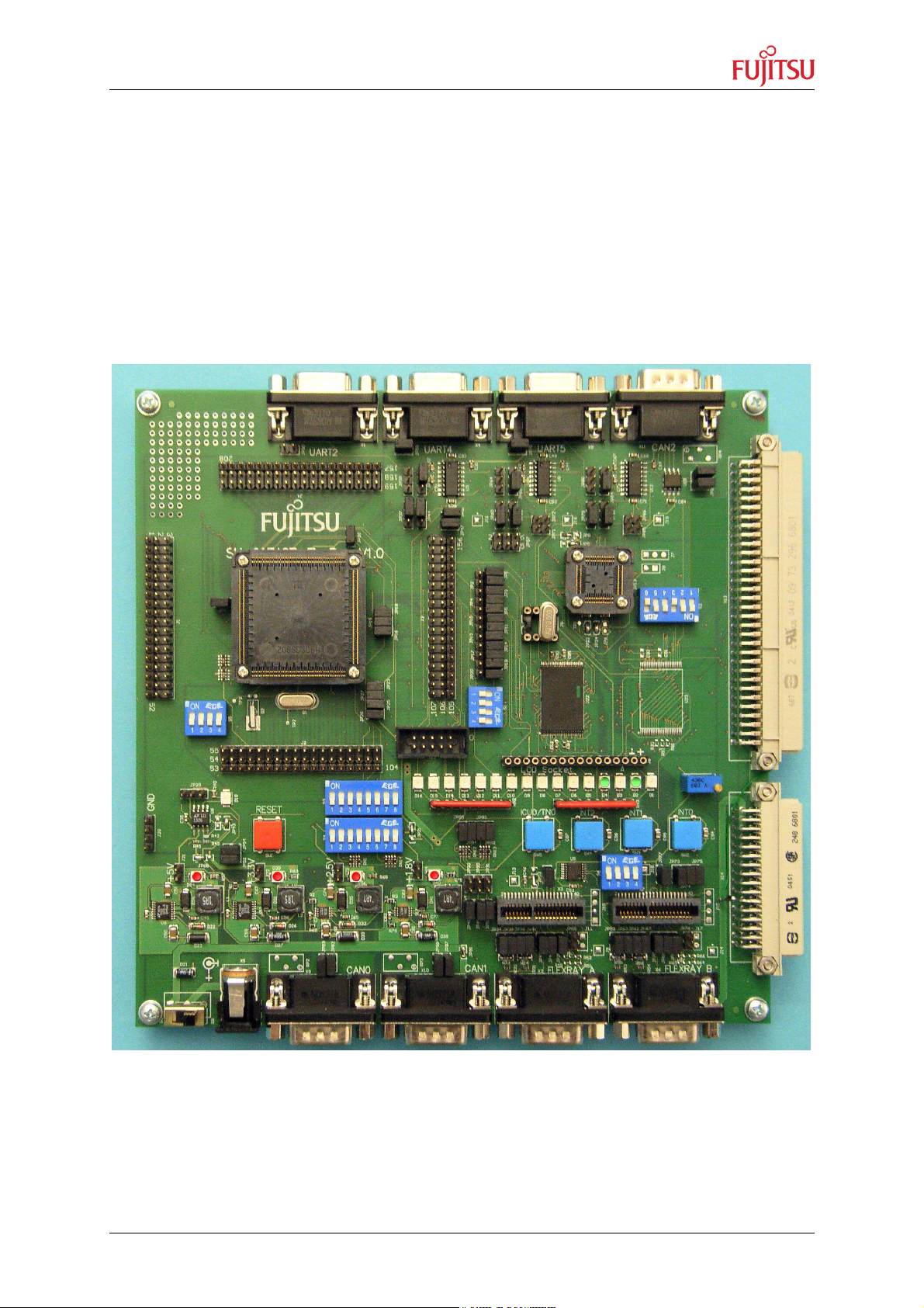
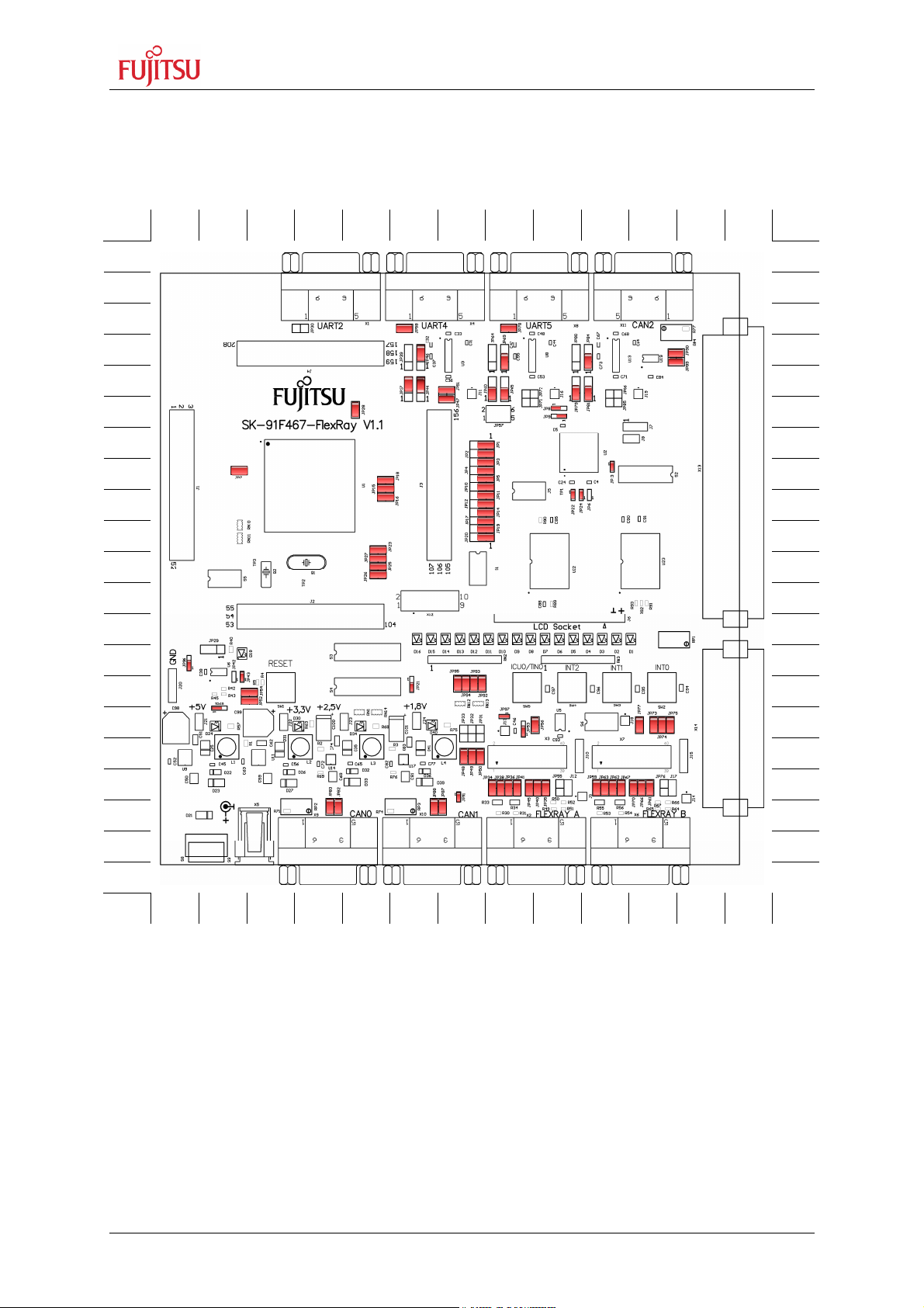
2.2 Jumper Location
The following picture shows the silk plot of the starter kit with marked default jumper settings.
A B C D E F G H J K L M N
1 1
2 2
3 3
4 4
5 5
6 6
7 7
8 8
9 9
10 10
11 11
12 12
13 13
14 14
15 15
16 16
17 17
18 18
19 19
20 20
21
21
A B C D E F G H J K L M N
Figure 2-6: Default Jumper Settings
FMEMCU-UG-910017-11 - 16 - © Fujitsu Microelectronics Europe GmbH
SK-91F467-FLEXRAY V1.1
Installation
2.3 Software Installation
2.3.1 Installation of Softune Workbench
Fujitsu supplies a full working 32bit development environment with the “SK-91F467FLEXRAY” starter kit called Softune Workbench V6. The Softune Workbench also supports
a monitor debugger which is pre-programmed into the internal Flash memory of the “SK91F467-FLEXRAY”. To develop own software and to work with the Monitor Debugger of the
“SK-91F467-FLEXRAY” the Softune Workbench development environment must be installed
first. Follow the instructions for successful installation of the Softune Workbench.
1) Before starting the installation setup ensure that you are logged in with administrator
or power user permissions, otherwise the Softune installation will fail! Be aware that
Softune does not support multi-user support. Therefore install- and user login must
be the same.
2) Browse on the starter kit CD-ROM into the directory Software\SWBInstall and start
the setup.exe
You can also start the installation using a browser by opening the index.html of the
CD-ROM. Use the link “Software\Softune Workbench\” in the left side frame.
3) Follow the installation instructions
4) For the default installation path it is recommended to use c:\Softune32
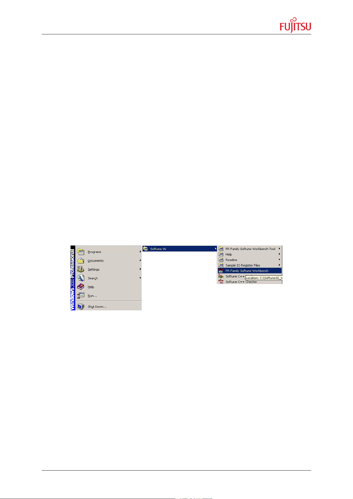
5) After the installation is finished, Softune Workbench for FR can be started via the
Windows “Start” menu
Figure 2-7: Softune Workbench start menu location
6) When Softune Workbench is started the following window will be shown
© Fujitsu Microelectronics Europe GmbH - 17 - FMEMCU-UG-910017-11

SK-91F467-FLEXRAY V1.1
Installation
Figure 2-8: Softune Workbench V6 IDE
FMEMCU-UG-910017-11 - 18 - © Fujitsu Microelectronics Europe GmbH
SK-91F467-FLEXRAY V1.1
1 2 3 4
MD0 MD1 MD2 nc
Jumpers and Switches
3 Jumpers and Switches
This chapter describes all jumpers and switches that can be modified on the starter kit. The
default setting is shown with a grey shaded area.
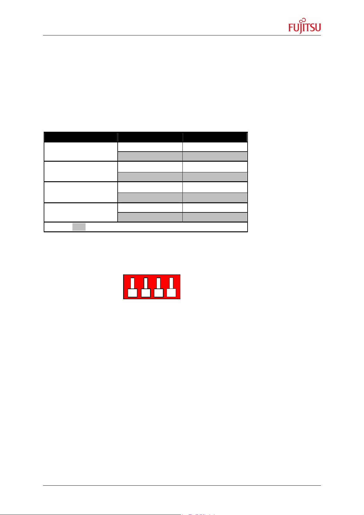
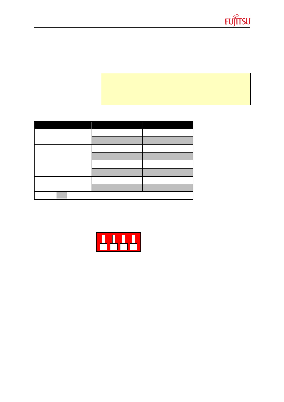
3.1 MCU Operating-Mode (S5)
The DIP-switch S5 is used to set the operating mode of the MCU. Ensure that the mode pin
settings correspond to the operation-mode of the application. For more detailed information
please check the Hardware-Manual of the microcontroller.
DIP switch Setting Logical value
S5/1 (MD0)
ON (closed) 1 (high)
OFF (open) 0 (low)
S5/2 (MD1)
ON (closed) 1 (high)
OFF (open) 0 (low)
S5/3 (MD2)
ON (closed) 1 (high)
OFF (open) 0 (low)
S5/4 (Not used)
ON (closed) Not connected
OFF (open) Not connected
Default: grey
Table 3-1: MCU Operating Mode
By default, the “Single Chip Run-Mode” of MB91F467DA is selected.
Dip-Switch S5
(default setting)
ON
OFF
Figure 3-1: MCU Mode Switch
© Fujitsu Microelectronics Europe GmbH - 19 - FMEMCU-UG-910017-11
SK-91F467-FLEXRAY V1.1
1 2 3 4 5 6
Jumpers and Switches
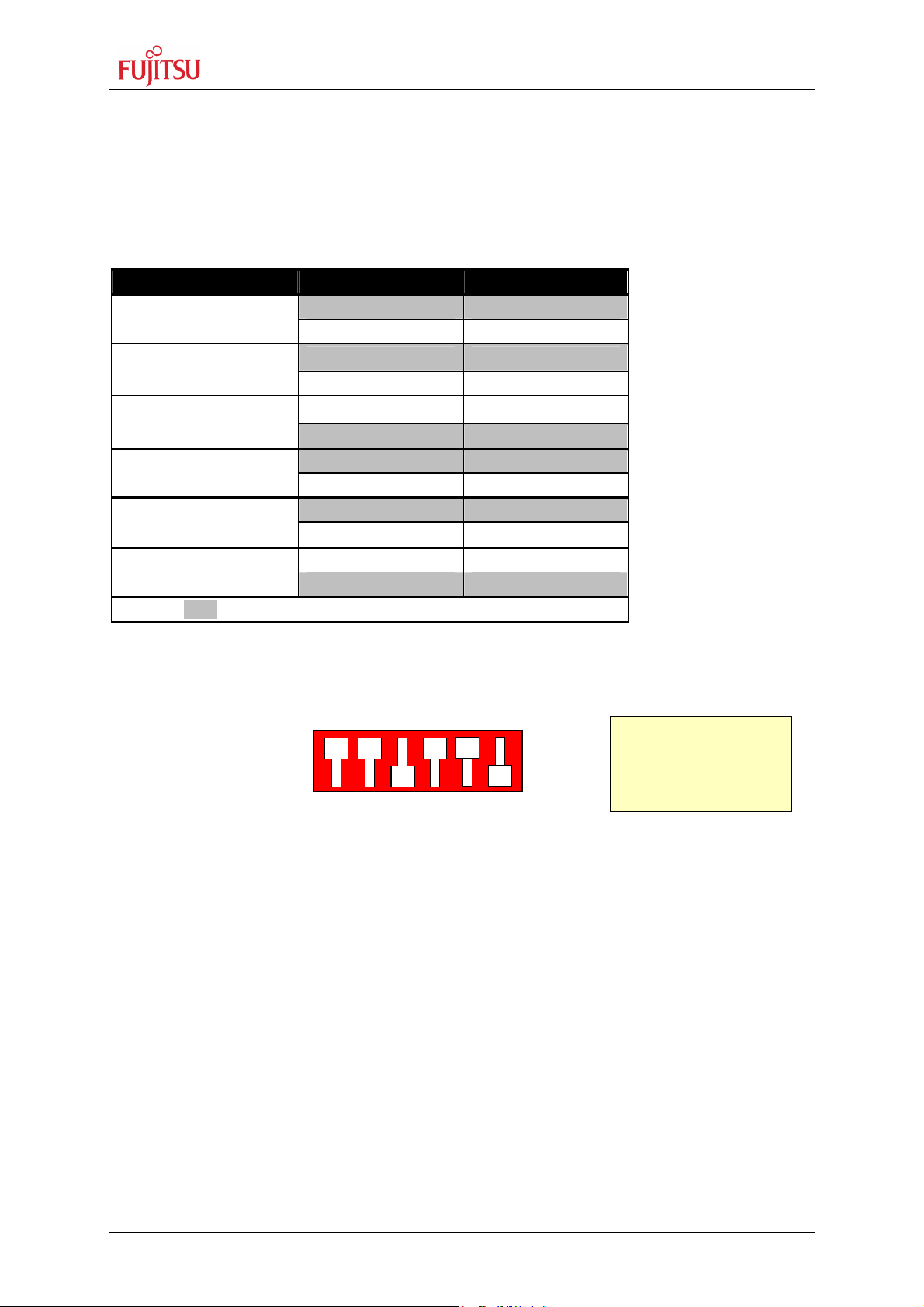
3.2 FlexRay CC Operating-Mode (S2)
The DIP-switch S2 is used to set the operating mode of the FlexRay communication
controller. Ensure that the mode pin settings correspond to the operation-mode of the
application. For more detailed information please check the Hardware-Manual of the
FlexRay CC.
DIP switch Setting Logical value
S2/1 (MD0)
ON (closed) 0 (low)
OFF (open) 1 (high)
S2/2 (MD1)
ON (closed) 0 (low)
OFF (open) 1 (high)
S2/3 (MD2)
ON (closed) 0 (low)
OFF (open) 1 (high)
S2/4 (MDE0)
ON (closed) 0 (low)
OFF (open) 1 (high)
S2/5 (MDE1)
ON (closed) 0 (low)
OFF (open) 1 (high)
S2/6 (MDE2)
ON (closed) 0 (low)
OFF (open) 1 (high)
Default: grey
Table 3-2: FlexRay CC Operating Mode
By default, the “16-bit non multiplexed mode” is selected.
Dip-Switch S2
(default setting)
MD0 MD1 MD2 MDE0 MDE1 MDE2
ON
OFF
Note:
The DIP-switch (S2)
on PCB rotated 180°
Figure 3-2: FlexRay CC Mode Switch
FMEMCU-UG-910017-11 - 20 - © Fujitsu Microelectronics Europe GmbH
SK-91F467-FLEXRAY V1.1
1 2 3 4
Jumpers and Switches
3.3 FlexRay CC SPI Settings (S1)
The DIP-switch S1 is used to set the FlexRay CC SPI settings, if the FlexRay CC is selected
to communicate with the MCU over SPI. For more detailed information please check the
Hardware-Manual of the FlexRay CC.
Note:
he DIP-switch (S1) is connected to the FlexRay CC in case the
T
jumpers setting are set to SPI communication mode. Please refer
to chapter 3.5 MCU-FlexRay CC Connection.
DIP switch Setting Logical value
S1/1 (MDS0)
ON (closed) 0 (low)
OFF (open) 1 (high)
S1/2 (MDS1)
ON (closed) 0 (low)
OFF (open) 1 (high)
S1/3 (MDS2)
ON (closed) 0 (low)
OFF (open) 1 (high)
S1/4 (Not used)
ON (closed) Not connected
OFF (open) Not connected
Default: grey
Table 3-3: FlexRay CC SPI Settings
The SPI function is not jet supported by MB88121!
Dip-Switch S1
(default setting)
MDS0 MDS1 MDS2 nc
ON
OFF
Figure 3-3: FlexRay CC SPI-Mode Switch
© Fujitsu Microelectronics Europe GmbH - 21 - FMEMCU-UG-910017-11
SK-91F467-FLEXRAY V1.1
Jumpers and Switches
3.4 Power Supply
There are four on-board switching regulators to provide the voltages 5V, 3.3V, 2.5V and
1.8V on the starter-kit. With the power ON/OFF-switch S8 or S9 (S9 is a soldering option to
use a different switch), the main input voltage from DC-connector X5 will be connected to the
VIN voltage of the board. The VIN voltage supplies the switching regulators and the VBat
voltage of the FlexRay physical layer driver modules from TZM (FT1080), if they are
connected to X3 and X7.
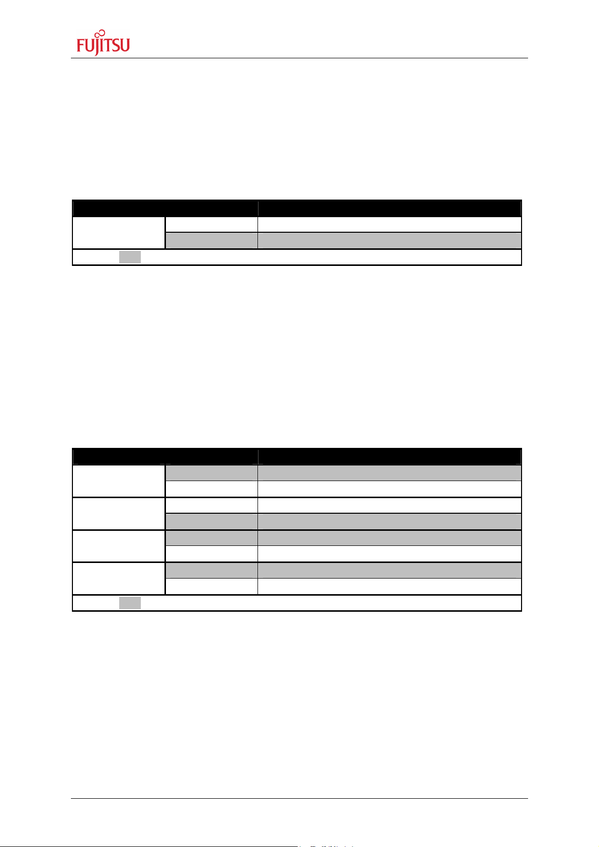
Switch Setting Description
S8 or S9
Default: grey
With JP91 the pins B14, B15 and B16 of the external bus interface connector X14 can be
connected to the VIN voltage, so that it is possible to supply the board from an external
connected board e.g. the Fujitsu FlexRay FPGA board.
ON (1-2) Power ON
OFF (2-3) Power OFF
Table 3-4: Power Switch
There is a triple supply monitor on-board, which monitors three of the four DC output
voltages and generates a system reset, in case with wrong levels of the on board voltages.
5V and 3.3V are always monitored and the third monitored voltage can be selected with the
solder jumpers JP42 and JP43.
With JP68 it is possible to select the whole board supply voltage Vcc to 5V or 3.3V
Jumper Setting Description
JP91
ON (closed) Vin connected to X14 pins B14, B15 and B16
OFF (open) Vin not connected to X14 pins B14, B15 and B16
JP42
ON (closed) Vcc1V8 connected to supply monitor
OFF (open) Vcc1V8 not connected to supply monitor
JP43
ON (closed) Vcc2V5 connected to supply monitor
OFF (open) Vcc2V5 not connected to supply monitor
JP68
1-2 Vcc is connected to 5V
2-3 Vcc is connected to 3.3V
Default: grey
Table 3-5: Power supply configurations
FMEMCU-UG-910017-11 - 22 - © Fujitsu Microelectronics Europe GmbH
Loading...