


MAW3147NC-NP
Table of contents
 Loading...
C141-E226-01EN
MAW3300NC/NP
MAW3147NC/NP
MAW3073NC/NP
HARD DISK DRIVES
PRODUCT/MAINTENANCE MANUAL

FOR SAFE OPERATION
Handling of This manual
This manual contains important information for using this product. Read thoroughly before using the
product. Use this product only after thoroughly reading and understanding especially the section “Important
Alert Items” in this manual. Keep this manual handy, and keep it carefully.
FUJITSU makes every effort to prevent users and bystanders from being injured or from suffering damage
to their property. Use the product according to this manual.
IMPORTANT NOTE TO USERS
READ THE ENTIRE MANUAL CAREFULLY BEFORE USING THIS PRODUCT.
INCORRECT USE OF THE PRODUCT MAY RESULT IN INJURY OR DAMAGE
TO USERS, BYSTANDERS OR PROPERTY.
While FUJITSU has sought to ensure the accuracy of all information in this manual, FUJITSU assumes no
liability to any party for any damage caused by any error or omission contained in this manual, its updates
or supplements, whether such errors or omissions result from negligence, accident, or any other cause. In
addition, FUJITSU assumes no liability with respect to the application or use of any porduct or system in
accordance with the descriptions or instructions contained herein; including any liability for incidental or
consequential damages arising therefrom.
FUJTSU DISCLAIMS ALL WARRANTIES REGARDING THE INFORMATION CONTAINED
HEREIN, WHETHER EXPRESSED, IMPLIED, OR STATUTORY.
FUJITSU reserves the right to make changes to any products described herein without further notice and
without obligation.
This product is designed and manufactured for use in standard applications such as office work, personal
devices and household appliances. This product is not intended for special uses (atomic controls,
aeronautic or space systems, mass transport vehicle operating controls, medical devices for life support, or
weapons firing controls) where particularly high reliability requirements exist, where the pertinent levels of
safety are not guaranteed, or where a failure or operational error could threaten a life or cause a physical
injury (hereafter referred to as "mission-critical" use). Customers considering the use of these products for
mission-critical applications must have safety-assurance measures in place beforehand. Moreover, they are
requested to consult our sales representative before embarking on such specialized use.
The contents of this manual may be revised without prior notice.
The contents of this manual shall not be disclosed in any way or reproduced in any media without the
express written permission of Fujitsu Limited.
All Right Reserved, Copyright © FUJITSU LIMITED 2005
C141-E226

REVISION RECORD
Edition Date published Revised contents
01 June, 2005
Specification No.: C141-E226-**EN
C141-E226 i

Related Standards
Product specifications and functions described in this manual comply with the following ANSI
(*1) standards.
Document number Title
T10/1236D Rev.20
[NCITS.351:2001]
T10/996D Rev.8c
[NCITS.306:1998]
T10/1157D Rev.24 SCSI Architecture Model-2 (SAM-2)
T10/1365D Rev.10 SCSI Parallel Interface-4 (SPI-4)
*1 ANSI = American National Standard Institute
In case of conflict between this manual and any referenced document, this manual takes
precedence.
SCSI Primary Commands-2 (SPC-2)
SCSI-3 Block Commands (SBC)
ii C141-E226

PREFACE
This manual describes the MAW3300NC/NP, MAW3147NC/NP, and MAW3073NC/NP 3.5 inch SCSI
disk drive.
This manual details the specifications and functions of the above disk drive, and gives the requirements and
procedures for installing it into a host computer system.
This manual is written for users who have a basic understanding of SCSI disk drives and their use in
computer systems. The MANUAL ORGANIZATION section describes organization and scope of this
manual. The need arises, use the other manuals.
OVERVIEW OF MANUAL
This manual consists of the following seven chapters and two appendixes:
CHAPTER 1 GENERAL DESCRIPTION
This chapter introduces the standard features, hardware, and system configuration of the HDD.
CHAPTER 2 SPECIFICATIONS
This chapter gives detailed specifications of the HDD and the installation environment.
CHAPTER 3 DATA FORMAT
This chapter describes the data structure of the disk, the address method, and what to do about media
defects.
CHAPTER 4 INSTALLATION REQUIREMENTS
This chapter describes the basic physical and electrical requirements for installing the disk drives.
CHAPTER 5 INSTALLATION
This chapter explains how to install the disk drives. It includes the notice and procedures for setting device
number and operation modes, mounting the disk drive, connecting the cables, and confirming drive
operation.
CHAPTER 6 DIAGNOSTICS AND MAINTENANCE
This chapter describes the automatic diagnosis and maintenance of the disk drive. This chapter also
describes diagnostic methods for operation check and the basics of troubleshooting the disk drives.
CHAPTER 7 ERROR ANALYSIS
This chapter describes in details how collect the information for error analysis and how analyze collected
error information.
APPENDIX A TO B
The appendixes give supplementary information, including a list of setting items and the signal assignments
of interface connector.
C141-E226 iii
CONVENTIONS USED IN THIS MANUAL
The MAW3300NC/NP, MAW3147NC/NP, and MAW3073NC/NP disk drives are described as "the hard
disk drive (HDD)", "the disk drive" or "the device" in this manual.
Decimal number is represented normally.
Hexadecimal number is represented as X'17B9', 17B9h or 17B9H.
Binary number is represented as "010".
CONVENTIONS FOR ALERT MESSAGES
This manual uses the following conventions to show the alert messages. An alert message consists of an
alert signal and alert statements. The alert signal consists of an alert symbol and a signal word or just a
signal word.
The following are the alert signals and their meanings:
CAUTION
IMPORTANT
In the text, the alert signal is centered, followed below by the indented message. A wider line space
precedes and follows the alert message to show where the alert message begins and ends. The following is
an example:
(Example)
Damage
Never remove any labels from the drive or deface them in any way.
The main alert messages in the text are also listed in the "Important Alert Items."
ATTENTION
Please for ward any comments you may have regarding thi s manua l .
To make this manual easier for users to understand, opinions from readers are needed. Please write your
opinions or requests on the Comment at the back of this manual and forward it to the address described in
the sheet.
This indicates that either minor or moderate
personal injury may occur if the user does not
perform the procedure correctly.
This indicates information that the helps the user
use the product more effectively.
CAUTION
iv C141-E226
Important Alert Items
Important Alert Messages
The important alert messages in this manual are as follows:
A hazardous situation could result in minor or moderate personal injury if the
user does not perform the procedure correctly. This alert signal also indicates
that damages to the product or other property may occur if the user does not
perform the procedure correctly.
Task Alert message Page
Specification Data loss
The drive adopts Reed-Solomon code for ECC.
The sector-data is divided into 3 interleaving sectors, and ECC is performed
in each sector where the maximum number of errors
(up to 9 byte) can be corrected. [Total maximum byte: 9 byte
( interleave) = 27 byte]
If the error of read sector keeps allowable error byte number, correction is
performed.
However, if error byte exceeds its allowable number, correction may not be
performed properly.
Installation Damage
Never remove any labels from the drive or deface them in any way.
Hot temperature
To prevent injury, never touch the drive while it is hot. The DE and LSI
become hot during operation and remain hot immediately after turning off
the power.
Data loss
1. The user must not change the setting of terminals not described in this
section. Do not change setting status set at factory shipment.
2. Do not change the setting of terminals except following setting pins
during the power is turned on.
• Write protect: Pin pair 9/10 of the CN2 setting terminal
3. To short the setting terminal, use the short plug attached when the device
is shipped from the factory.
Damage
1. Make sure that system power is off before connecting or disconnecting
cables.
2. Do not connect or disconnect cables when power is on.(except NC
model)
(NP model only)
2-5
×
3
4-4
5-1
5-5
5-12
C141-E226 v

Task Alert message Page
Installation Damage
1. Be careful of the insertion orientation of the SCSI connectors. With the
system in which terminating resistor power is supplied via the SCSI
cable, if the power is turned on, the overcurrent protection fuse of the
terminating resistor power supplier may be blown or the cable may be
burnt if overcurrent protection is not provided.
When the recommended parts listed in Table 4.2 are used, inserting the
cables in the wrong direction can be prevented.
2. To connect SCSI devices, be careful of the connection position of the
cable. Check that the SCSI device with the terminating resistor is the last
device connected to the cable.
Diagnostics and
Maintenance
Damage
Data loss
When the SEND DIAGNOSTIC command terminates with the CHECK
CONDITION status, the initiator must collect the error information using the
REQUEST SENSE command. The RECEIVE DIAGNOSTIC RESULTS
command cannot read out the error information detected in the selfdiagnostics.
Caution
1. To avoid shocks, turn off the power before connecting or disconnecting a
cable, connector, or plug.
2. To avoid injury, do not touch the mechanical assembly during disk drive
operation.
3. Do not use solvents to clean the disk drive.
Caution
1. Always ground yourself with a wrist strap connected to ground before
handling. ESD (Electrostatics Discharge) may cause the damage to the
device.
2. To prevent electrical damage to the disk drive, turn the power off before
connecting or disconnecting a cable, connector, or plug.
3. Do not remove a PCA. This operation is required to prevent unexpected
or unpredictable operation.
4. Do not use a conductive cleaner to clean a disk drive assembly.
5. Ribbon cables are marked with a colored line. Connect the ribbon cable
to a cable connector with the colored wire connected to pin 1.
1. Never remove any labels from the drive.
2. Never open the disk enclosure for any reason.
Doing so will void any warranties.
Data loss
Save data stored on the disk drive to other media before requesting repair.
Fujitsu does not assume responsibility if data is destroyed during servicing
or repair.
5-12
6-4
6-5
6-6
6-14
6-7
vi C141-E226

MANUAL ORGANIZATION
PRODUCT/
MAINTENANCE
MANUAL
(This manual)
SCSI PHYSICAL
INTERFACE
SPECIFICATIONS
SCSI LOGICAL
INTERFACE
SPECIFICATIONS
1. General Description
2. Specifications
3. Data Format
4. Installation Requirements
5. Installation
6. Diagnostics and Maintenance
7. Error Analysis
1. SCSI BUS
2. SCSI MESSAGE
3. ERROR RECOVERY
1. Command Processing
2. Data Buffer Management
3. Command Specifications
4. Parameter Data Formats
5. Sense Data and Error Recovery Method
6. Disk Media Management
C141-E226 vii

This page is intentionally left blank.

CONTENTS
page
CHAPTER 1
1.1 Standard Features..............................................................................................................1-2
1.2 Hardware Structure............................................................................................................1-6
1.3 System Configuration........................................................................................................1-8
CHAPTER 2 SPECIFICATIONS...........................................................................................2-1
2.1 Hardware Specifications....................................................................................................2-1
2.1.1 Model name and order number..........................................................................................2-1
2.1.2 Function specifications......................................................................................................2-2
2.1.3 Environmental specifications ............................................................................................2-4
2.1.4 Error rate...........................................................................................................................2-5
2.1.5 Reliability..........................................................................................................................2-5
2.2 SCSI Function Specifications............................................................................................2-7
CHAPTER 3 DATA FORMAT...............................................................................................3-1
3.1 Data Space.........................................................................................................................3-1
3.1.1 Cylinder configuration.......................................................................................................3-1
3.1.2 Alternate spare area ...........................................................................................................3-3
GENERAL DESCRIPTION ............................................................................1-1
3.1.3 Track format......................................................................................................................3-5
3.1.4 Sector format.....................................................................................................................3-6
3.1.5 Format capacity.................................................................................................................3-8
3.2 Logical Data Block Addressing.........................................................................................3-8
3.3 Defect Management...........................................................................................................3-10
3.3.1 Defect list..........................................................................................................................3-10
3.3.2 Alternate block allocation .................................................................................................3-10
CHAPTER 4 INSTALLATION REQUIREMENTS.............................................................4-1
4.1 Mounting Requirements....................................................................................................4-1
4.1.1 External dimensions..........................................................................................................4-1
4.1.2 Mounting orientations.......................................................................................................4-4
4.1.3 Notes on mounting............................................................................................................4-4
4.2 Power Supply Requirements .............................................................................................4-8
4.3 Connection Requirements..................................................................................................4-11
4.3.1 SCA2 connector type 16-bit SCSI model (NC model)......................................................4-11
C141-E226 ix

68-pin connector type 16-bit SCSI model (NP model)......................................................4-13
4.3.2
4.3.3 Cable connector requirements...........................................................................................4-20
4.3.4 External operator panel (on NP model drives only)..........................................................4-21
CHAPTER 5 INSTALLATION...............................................................................................5-1
5.1 Notes on Handling Drives................................................................................................. 5-1
5.2 Connections.......................................................................................................................5-3
5.3 Setting Terminals .............................................................................................................. 5-5
5.3.1 SCSI ID setting..................................................................................................................5-6
5.3.2 Each mode setting.............................................................................................................5-8
5.3.3 Mode settings....................................................................................................................5-10
5.4 Mounting Drives................................................................................................................5-11
5.4.1 Check before mounting .....................................................................................................5-11
5.4.2 Mounting procedures.........................................................................................................5-11
5.5 Connecting Cables.............................................................................................................5-12
5.6 Confirming Operations after Installation and Preparation for Use....................................5-13
5.6.1 Confirming initial operations.............................................................................................5-13
5.6.2 Checking SCSI connection................................................................................................5-14
5.6.3 Formatting.........................................................................................................................5-17
5.6.4 Setting parameters.............................................................................................................5-19
5.7 Dismounting Drives...........................................................................................................5-23
5.8 Spare Disk Drive...............................................................................................................5-23
CHAPTER 6 DIAGNOSTICS AND MAINTENANCE........................................................6-1
6.1 Diagnostics........................................................................................................................6-1
6.1.1 Self-diagnostics.................................................................................................................6-1
6.1.2 Test programs....................................................................................................................6-4
6.2 Maintenance Information..................................................................................................6-5
6.2.1 Precautions........................................................................................................................6-5
6.2.2 Maintenance requirements.................................................................................................6-6
6.2.3 Maintenance levels............................................................................................................6-7
6.2.4 Revision numbers..............................................................................................................6-8
6.2.5 Tools and test equipment...................................................................................................6-9
6.2.6 Tests..................................................................................................................................6-9
6.3 Operation Check................................................................................................................6-11
6.3.1 Initial seek operation check...............................................................................................6-11
6.3.2 Operation test....................................................................................................................6-11
x C141-E226

Diagnostic test...................................................................................................................6-11
6.3.3
6.4 Troubleshooting Procedures..............................................................................................6-12
6.4.1 Outline of troubleshooting procedures..............................................................................6-12
6.4.2 Troubleshooting with disk drive replacement in the field .................................................6-12
6.4.3 Troubleshooting at the repair site......................................................................................6-14
6.4.4 Troubleshooting with parts replacement in the factory.....................................................6-15
6.4.5 Finding possibly faulty parts.............................................................................................6-15
CHAPTER 7 ERROR ANALYSIS..........................................................................................7-1
7.1 Error Analysis Information Collection..............................................................................7-1
7.1.1 Sense data..........................................................................................................................7-1
7.1.2 Sense key, additional sense code, and additional sense code qualifier..............................7-1
7.2 Sense Data Analysis..........................................................................................................7-3
7.2.1 Error information indicated with sense data......................................................................7-3
7.2.2 Sense data (3-0C-03), (4-40-xx), and (4-C4-xx) ...............................................................7-4
7.2.3 Sense data (1-1x-xx), (3-1x-xx) and (E-1D-00): Disk read error....................................7-4
7.2.4 Sense data (4-44-xx), (5-2x-xx), (5-3D-00), (5-90-00), (B-44-xx), (B-47-xx),
(B-48-00), (B-49-00), (B-4D-xx) and (B-4E-00): SCSI interface error..........................7-4
APPENDIX A SETTING TERMINALS..................................................................................A-1
A.1 Setting Terminals (on NP model only)..............................................................................A-2
APPENDIX B CONNECTOR SIGNAL ALLOCATION.......................................................B-1
B.1 SCSI Connector Signal Allocation: SCA2 type LVD 16-bit SCSI...................................B-2
B.2 SCSI Connector Signal Allocation: 68-pin type LVD 16-bit SCSI..................................B-3
INDEX ........................................................................................................................................IN-1
C141-E226 xi

FIGURES
page
Figure 1.1
Figure 1.2 NP model drives outer view...............................................................................................1-6
Figure 1.3 System configuration..........................................................................................................1-8
NC model drives outer view...............................................................................................1-6
Figure 3.1
Figure 3.2 Spare area in cell ................................................................................................................3-4
Figure 3.3 Alternate cylinder...............................................................................................................3-4
Figure 3.4 Track format.......................................................................................................................3-5
Figure 3.5 Track skew/head skew........................................................................................................3-6
Figure 3.6 Sector format......................................................................................................................3-6
Figure 3.7 Alternate block allocation by FORMAT UNIT command...............................................3-12
Figure 3.8 Alternate block allocation by REASSIGN BLOCKS command ......................................3-13
Figure 4.1
Figure 4.2 NP model dimensions.........................................................................................................4-3
Figure 4.3 HDD orientations................................................................................................................4-4
Figure 4.4 Mounting frame structure...................................................................................................4-5
Figure 4.5 Limitation of side-mounting...............................................................................................4-6
Figure 4.6 Surface temperature measurement points...........................................................................4-7
Figure 4.7 Service clearance area ........................................................................................................ 4-7
Figure 4.8 Spin-up current waveform (+12V DC)...............................................................................4-8
Cylinder configuration........................................................................................................3-2
NC model dimensions.........................................................................................................4-2
Figure 4.9 Power on/off sequence (1)..................................................................................................4-8
Figure 4.10 Power on/off sequence (2)..................................................................................................4-9
Figure 4.11 Power on/off sequence (3)..................................................................................................4-9
Figure 4.12 AC noise filter (recommended) ........................................................................................4-11
Figure 4.13 NC connectors location ....................................................................................................4-11
Figure 4.14 SCA2 type 16-bit SCSI connector....................................................................................4-12
Figure 4.15 NP connectors and terminals location ..............................................................................4-13
Figure 4.16 68-pin type 16-bit SCSI interface connector ....................................................................4-14
Figure 4.17 Power supply connector (68-pin type 16-bit SCSI)..........................................................4-14
Figure 4.18 External operator panel connector (CN1).........................................................................4-15
Figure 4.19 External operator panel connector (CN2).........................................................................4-15
Figure 4.20 16-bit SCSI ID external input...........................................................................................4-16
xii C141-E226

Figure 4.21
Figure 4.22 SCSI cables connection....................................................................................................4-19
Figure 4.23 External operator panel circuit example...........................................................................4-21
Figure 5.1 SCSI bus connections ........................................................................................................5-4
Figure 5.2 Setting terminals location (on NP models only).................................................................5-5
Figure 5.3 CN2 setting terminal (on NP models only).........................................................................5-6
Figure 5.4 Checking the SCSI connection (A)...................................................................................5-15
Figure 5.5 Checking the SCSI connection (B)...................................................................................5-16
Output signal for external LED........................................................................................4-18
Figure 6.1
Figure 6.2 Indicating revision numbers................................................................................................6-9
Figure 6.3 Test flowchart...................................................................................................................6-10
Figure 7.1
Revision label (example)....................................................................................................6-8
Format of extended sense data............................................................................................7-2
C141-E226 xiii

TABLES
page
Table 2.1
Table 2.2 Function specifications.......................................................................................................2-2
Table 2.3 Environmental/power requirements....................................................................................2-4
Table 2.4 SCSI function specifications...............................................................................................2-7
Model names and order numbers........................................................................................2-1
Table 3.1
Table 4.1
Table 4.2 Recommended components for connection......................................................................4-20
Table 5.1
Table 5.2 Setting SCSI terminator power supply (NP model)............................................................5-8
Table 5.3 Motor start mode setting.....................................................................................................5-8
Table 5.4 Write protect setting (NP model)........................................................................................5-9
Table 5.5 Setting of the SCSI interface operation mode (NP model).................................................5-9
Table 5.6 Setting the bus width of the SCSI interface (NP model)....................................................5-9
Table 5.7 Default mode settings (by CHANGE DEFINITION command)......................................5-10
Table 5.8 Setting check list (NP model only)...................................................................................5-11
Table 6.1
Table 6.2 System-level field troubleshooting...................................................................................6-13
Table 6.3 Disk drive troubleshooting...............................................................................................6-14
Format capacity..................................................................................................................3-8
Surface temperature check point.........................................................................................4-6
SCSI ID setting................................................................................................................... 5-7
Self-diagnostic functions ....................................................................................................6-1
Table 7.1
Table A.1
Table B.1
Table B.2 SCSI connector (68-pin type LVD 16-bit SCSI): CN1.....................................................B-3
xiv C141-E226
Definition of sense data......................................................................................................7-3
CN2 setting terminal (on NP model drives only)...............................................................A-2
SCSI connector (SCA2 type LVD 16-bit SCSI): CN1.....................................................B-2

CHAPTER 1 GENERAL DESCRIPTION
1.1 Standard Features
1.2 Hardware Structure
1.3 System Configuration
This chapter describes the feature and configuration of the hard disk drives (HDDs).
The drives are high performance large capacity 3.5 inch hard disk drives with an embedded SCSI controller.
The drives support the Small Computer System Interface (SCSI) as described in the ANSI SCSI SPI-4
[T10/1365D Rev.10] to the extent described in this manual.
The flexibility and expandability of the SCSI, as well as the powerful command set of the HDD, allow the
user to construct a high-performance reliable disk subsystem with large storage capacity.
The data format can be changed from the format at factory shipment by reinitializing with the user's system.
Refer to Chapter 6 “Disk Media Management” of the SCSI Logical Interface Specifications for details.
C141-E226 1-1

1.1 Standard Features
(1) Compactness
Since the SCSI controller circuit is embedded in the standard 3.5 inch hard disk drive form factor,
the HDD is extremely compact. The HDD can be connected directly to the SCSI bus of the host
system.
(2) Restriction of Use of Hazardous Substances
The amounts of hazardous substances in use in these HDDs have been reduced in accordance with
the Restriction of Use of Hazardous Substances (RoHS) Directive recently issued by European
Union (EU).
Note:
At present, the permissible limits on the use of certain materials specified by the RoHS
directive have not been determined. In such cases, we are using the original criteria set by
Fujitsu Limited while referring to the restrictions already established by End-of-Life Vehicle
(ELV) Directive or by the national environmental laws of the EU member nations.
(3) SCSI standard
The HDD provides not only SCSI basic functions but also the following features:
• Arbitration
• Disconnection/Reconnection
• Data bus parity
The SCSI commands can manipula te data through logical block addressing regardless of the
physical characteristics of the disk drive. This allows software to accommodate future expansion
of system functions.
(4) 8-bit SCSI/16-bit SCSI
The HDD has 16-bit data bus width (16-bit SCSI), which have the wide transfer function suitable
for SCSI-2. 8-bit data bus is available only with NP model.
See subsection 5.3.2 for details of the bus width setting.
For the ultra SCSI model, number of connectable SCSI devices on the same SCSI bus is varied as
follows.
• 8-bit SCSI: 8 drives max. (option for NP model)
• 16-bit SCSI: 16 drives max.
1-2 C141-E226

(5) High speed data transfer
Such a high data transfer rate on the SCSI bus can be useful with the large capacity buffer in the
HDD.
• 8-bit SCSI: The data transfer rate on the SCSI bus is 40 MB/s maximum at the
synchronous mode.
• 16-bit SCSI: The data transfer rate on the SCSI bus is 320 MB/s maximum at the paced
transfer synchronous mode.
Note:
The maximum data transfer rate in asynchronous mode may be limited by the response time of
initiator and the length of SCSI bus length. The maximum data transfer rate in synchronous
mode may be limited by the cable length, transmission characteristics of the SCSI bus and the
connected SCSI device number.
(6) Continuous block proce ssi ng
The addressing method of data blocks is logical block address. The initiator can access data by
specifying block number in a logically continuous data space without concerning the physical
structure of the track or cylinder boundaries.
The continuous processing up to [64K-1] blocks in a command can be achieved, and the HDD can
perform continu ous read/ w rite operat ion when processin g data bl ocks on sev eral track s or cy li nder.
(7) Multi-segment data buffer
The data buffe r is 8M bytes. Data i s transferred between SCSI bus and disk media t hrough this
data buffer. This feature provides the suitable usage environment for users.
Since the initiator can control the disconnect/reconnect timing on the SCSI bus by specifying the
condition of stored data to the data buffer or empty condition of the data buffer, the initiator can
perform the effective input/output operations with utilizing high data transfer capability of the
SCSI bus regardless of actual data transfer rate of the disk drive.
(8) Cache feature
After executing the READ command, the HDD reads automatically and stores (prefaces) the
subsequent data blocks into the data buffer (Read-ahead caching).
The high speed sequential data access can be achieved by tran sferrin g th e data from the data bu ff er
without reassessi ng th e disk in case the s ubsequ ent com m an d requests th e perfected data block s.
The write cache feature is supported. When this f eature is en abled, the statu s report is is sued w ith out
waiting for completion of w rite processing to disk media, thereby en abling hig h speed write processing.
C141-E226 1-3

IMPORTANT
When Write cache is enabled, you should ensure that the cashed data is
surely flushed to the disk media befo re you turn off the drive's power.
To ensure it, you should issue either the SYNCHRONIZE CASHE
command or the STOP UNIT command with specifying “0” to the
Immediate bit and then confirm that the command is surely terminated
with the GOOD STATUS.
(9) Command queuing fe ature
The HDD can queue maximum 128 commands, and optimizes the issuing order of queued
commands by the reordering function. This feature realizes the high speed processing.
(10) Reserve and release functions
The HDD can be accessed exclusively in the multi-host or multi-initiator environment by using the
reserve and release functions.
(11) Error recovery
The HDD can try to recover from errors in SCSI bus or the disk drive using its powerful retry
processing. If a recoverable data check occurs, error-free data can be transferred to the initiator
after being corrected in the data buffer. The initiator software is released from the complicated
error recover processing by these error recovery functions of the HDD.
(12) Automatic alternate block reassignment
If a defective data block is detected during read or write the HDD can automatically reassign its
alternate data block.
(13) Programmable data block length
Data can be accessed in fixed-block length units. The data block length is programmable, and can
be specified at initializing with a multiple of four within the range of 512 to 528 bytes.
IMPORTANT
Error rate increase
1. The drive format at factory shipment is generally 512 byte.
2. The Recoverable Error of the drive might increase when the
format would be modified from 512 bytes to the following values:
516 bytes, 520 bytes, 524 bytes, and 528 bytes.
3. The Recoverable Error referred in 2) is sense data (1-13-xx).
1-4 C141-E226

(14) Defective block slipping
A logical data block can be reallocated in a physical sequence by slipping the defective data block
at formatting. This results in high speed contiguous data block processing without a revolution
delay due to defective data block.
(15) High speed positioning
A rotary voice coil motor achieves fast positioning with high performance access control.
(16) Large capacity
A large capacity can be obtained from the HDD by dividing all cylinders into several partitions and
changing the recording density on each partition (constant density recording). The disk subsystem
with large capacity can be constructed in the good space efficiency.
(17) Start/Stop of spindle motor
Using the SCSI command, the host system can start and stop the spindle motor.
(18) Diagnosis
The HDD has a diagnostic capability which checks internal controller functions and drive
operations to facilitate testing and repair.
(19) Low power consumption
By using highly integrated LSI components, the power consumption of the HDD is very low, and
this enables the unit to be used in wide range of environmental conditions.
(20) Low noise and low vibration
The noise level is low; approx. 3.4 Bels at Ready for the drive. This makes it ideal for office use.
(21) Microcode downloading
The HDD implements the microcode download feature. This feature easily achieves maintenance
and function enhancement of the HDD.
C141-E226 1-5
1.2 Hardware Structure
An outer view of the HDD is given in Figures 1.1 and 1.2. The HDD has a disk enclosure (DE)
and a printed circuit assembly (PCA). The DE includes heads on an actuator and disks on a
spindle motor mounted on the DE. The PCA includes a read/write circuit and a controller circuit.
Figure 1.1 NC model drives outer view
Figure 1.2 NP model drives outer view
1-6 C141-E226

(1) Disks
The disks have an outer diameter of 84 mm (3.3 inch) and an inner diameter of 25 mm (0.98 inch).
The disks are good for at least 50,000 contact starts and stops.
(2) Heads
The MR (Magnet - Resistive) of the CSS (contact start/stop) type heads are in contact with the
disks when the disks are not rotating, and automatically float when the rotation is started.
(3) Spindle motor
The disks are rotated by a direct-drive hall-less DC spindle motor. The motor speed is controlled
by a feedback circuit using the counter electromotive current to precisely maintain of the specified
speed.
(4) Actuator
The actuator, which uses a rotary voice coil motor (VCM), consumes little power and generates
little heat. The heads at the end of the actuator arm are controlled and positioned via feedback of
servo information in the data.
The heads are positioned on the CCS zone over the disks when the power is off or the spindle
motor is stopped.
(5) Air circulation (recirculation filter, breather filter)
The disk enclosure (DE) configures a clean room to keep out particle and other contaminants. The
DE has a closed-loop air recirculation system. Using the movement of the rotating disks, air is
continuously cycled through a filter. This filter will trap any particle floating inside the e nc l osure
and keep the air inside the DE contaminant free. To prevent negative pressure in the vicinity of the
spindle when the disks begin rotating, a breather filter is attached. The breather filter also
equalizes the internal air pressure with the atmospheric pressure due to surrounding temperature
changes.
(6) Read/write circuit
The read/write circuit utilizes a read channel mounted with a head IC that supports high-speed
transmission and an MEEPR4ML (Modified Enhanced Extended Partial Response Class 4
Maximum Likelihood) modulation/demodulation circuit in order to prevent errors being triggered
by external noise and to improve data reliability.
(7) Controller circuit
The controller circuit uses LSIs to increase the reliability and uses a high speed microprocessing
unit (MPU) to increase the performance of the SCSI controller.
C141-E226 1-7
1.3 System Configuration
Figure 1.3 shows the system configuration. The drives are connected to the SCSI bus of host
systems and are always operated as target. The drives perform input/output operation as specified
by SCSI devices which operate as initiator.
SCSI bus
HDD
HDD
(#14)
(#15)
Figure 1.3 System configuration
1-8 C141-E226

(1) SCSI bus confi guration
Up to eight SCSI devices operating as an initiator or a target can be connected to the SCSI bus for
the 8-bit SCSI and up to 16 SCSI devices operating as an initiator or a target can be connected to
the SCSI bus for the 16-bit SCSI in any combination.
For example, the system can be configured as multi-host system on which multiple host computers
that operate as initiator or connected through the SCSI bus.
Using disconnect/ reconnect function, concurrent i nput/output processing is possible on multi-SCSI
devices.
(2) Addressing of peripheral device
Each SCSI device on the bus has its own unique address (SCSI ID:#n in Figure 1.3). For
input/output operation, a peripheral device attached to the SCSI bus that operates as target is
addressed in unit called as logical unit. A unique address (LUN: logical unit number) is assigned
for each logical unit.
The initiator selects one SCSI device by specifying that SCSI ID, then specifies the LUN to select
the peripheral device for input/output operation.
The HDD is constructed so that the whole volume of disk drive is a single logical unit, the
selectable number of SCSI ID and LUN are as follows:
• SCSI ID: 8-bit SCSI:Selectable from 0 to 7 (option for NP model, switch selectable)
16-bit SCSI:Selectable from 0 to 15 (switch selectable)
• LUN: 0 (fixed)
C141-E226 1-9

This page is intentionally left blank.

CHAPTER 2 SPECIFICATIONS
2.1 Hardware Specifications
2.2 SCSI Function Specifications
This chapter describes specifications of the HDD and the functional specifications of the SCSI.
2.1 Hardware Specifications
2.1.1 Model name and order number
Each model has a different recording capacities and interface connector type when shipped. Table
2.1 lists the model name and order number.
The data format can be changed by reinitializing with the user's system.
Table 2.1 Model names and order numbers
Model name Order number SCSI type
MAW3300NC CA06550-B400 SCA2, LVD
MAW3300NP CA06550-B460 68-pin, LVD
MAW3147NC CA06550-B200 SCA2, LVD
MAW3147NP CA06550-B260 68-pin, LVD
MAW3073NC CA06550-B100 SCA2, LVD
MAW3073NP CA06550-B160 68-pin, LVD
(*) 1GB=1,000,000,000 bytes
Capacity
(user area)
300.0 GB (*)
147.0 GB (*)
73.5 GB (*)
C141-E226 2-1

2.1.2 Function specifications
Table 2.2 shows the function specifications of the HDD.
Table 2.2 Function specifications
Item
Specification
MAW3300NC/NP MAW3147NC/NP MAW3073NC/NP
Formatted capacity/device (*1) 300.0 GB (*2) 147.0 GB (*2) 73.5 GB (*2)
Number of disks 4 3 1
Number of heads 8 5 2
Number of rotations min-1 (rpm) 10,025 ± 0.2%
Average latency time 2.99 ms
Seek time (*3)
(Read/Write)
Start/stop
time (*4)
Track to Track
Average
Full stroke
Start time
Stop time
0.2 ms/0.4 ms
4.5 ms/5.0 ms
10.0 ms/11.0 ms
30 s typ. (60 s max.)
30 s typ.
Recording mode 32/34 MEEPRML
External
dimensions
Height:
Width:
Depth:
25.4 mm
101.6 mm
146.0 mm
Weight 0.75 kg max.
Power consumption (*5) 9.5 W typ.
Fast 5 SCSI Cable length: 6 m max.
SingleEnded
Interface
Fast 10 SCSI Cable length: 3 m max.
Fast 20 SCSI
Cable length: 3 m max. (*6)
Cable length: 1.5 m max. (*7)
Ultra 2 Wide
LVD
U160
Cable length: 25 m max. (*8)
Cable length: 12 m max. (*9)
U320
Areal density 60 to 75 Gbits/inch2
Disk drive 132.4 MB/s
Data transfer
rate (*10)
SCSI
(Synchronous
320 MB/s max.
mode)
Logical data block length 512, 516, 520, 524, 528 byte (Fixed length) (*11)
SCSI command specification
SPI-4 (T10/1365D Rev.10), SAM-2 (T10/1157D Rev.24),
SPC-2 (T10/1236D Rev.20), SBC (T10/996D Rev.8c)
Data buffer 8 MB FIFO ring buffer (*12)
Acoustic noise (Idle) 3.4 Bels typ.
2-2 C141-E226
(*1) The formatted capacity can be changed by changing the logical block length and using spare sector
space. See Chapter 3 for the further information. The formatted capacity listed in the table is an
estimate for 512 bytes per sector.
(*2) 1GB=1,000,000,000 bytes
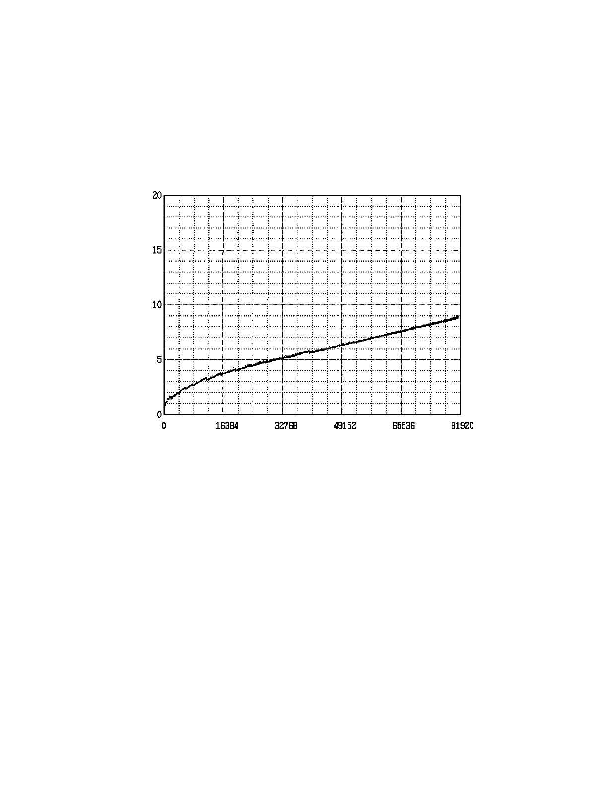
(*3) The seek time is as follows:
Seek time [ms]
Seek Difference [4096 Cyl/div]
(*4) The start time is the time from po wer on or start command to when the HDD is ready, and the stop
time is the time for disks to completely stop from power off or stop command.
(*5) This value indicates during idle mode. Power supply at nominal voltage ± 1%. 25°C ambient.
(*6) Up to 4 SCSI devices having capacitance of 25pF or less can use cable length of up to 3.0 m.
(*7) 5 to 8 SCSI devices having capacitance of 25pF or less can use cable length of up to 1.5 m.
(*8) 1 on 1 connection case.
(*9) 1 host, 15 devices case.
(*10) The maximum data transfer rate may be restricted to the response speed of initiator and by
transmission characteristics. 1MB/s=1,000,000 bytes/s.
(*11) Refer to 1.1(13).
(*12) 1MB=1,048,576 bytes
C141-E226 2-3

2.1.3 Environmental specifications
Table 2.3 lists environmental and power requirements.
Table 2.3 Environmental/power requirements
Item
MAW3300NC/NP MAW3147NC/NP MAW3073NC/NP
Operating 5 to 55°C
Non-operating –40 to 70°C
Temperature
(*1)
Transport
(within a week)
DE surface temperature
at operating
Gradient 15°C/h or less
Operating 5 to 95%RH
Non operating 5 to 95%RH
Relative
humidity
Transport
(within a week)
Maximum wet b ulb
temperature
Vibration
(*2)
Operating (*3) 0.6 mm (5 to 20 Hz)/9.8 m/s2 (1 G) (20 to 300 Hz) or less
Non-operating (*4) 3.1 mm (5 to 20 Hz)/49 m/s2 (5 G) (20 to 300 Hz) or less
Transport (packaged) 3.1 mm (5 to 20 Hz)/49 m/s
Operating 637.4 m/s2 (65 G)/2 ms duration
Shock (*2)
Non-operating 2205 m/s2 (225 G)/2 ms duration
Transport (packaged) 2205 m/s
Altitude
Operating –305 to +3,048 m (-1,000 to +10,000 feet)
Non-operating –305 to +12,192 m (-1,000 to +40,000 feet)
Idle 0.6 A ave.
Power
requirements
(*5)
+12V DC
±5 %
+5V DC
±5 % (*6)
Spin-up 3.0 A (peak within 100 µs)
Random
W/R
Idle 0.46 A ave.
Random
W/R
Ripple
(+5 V and +12 V)
(*1) For detail condition, see Section 4.1.
Specification
–40 to 70°C
5 to 60°C
5 to 95%RH
29°C (no condensation)
2
(5 G) (20 to 300 Hz) or less
2
(225 G)/2 ms duration
1.0 A (about 80 IOPS)
1.0 A (about 80 IOPS)
250 mVp-p or less (*7)
(*2) Vibration applied to the drive is measured at near the mounting screw hole on the frame as much
as possible.
(*3) At random seek write/read and default on retry setting with log sweep vibration.
(*4) At power-off state after installation
Vibration displacement should be less than 2.5 mm.
(*5) Input voltages are specified at the drive connector side, during drive ready state.
2-4 C141-E226
Loading...