


SPLIT TYPE
ROOM AIR CONDITIONER
WALL MOUNTEDtype
INVERTER
SERVICE INSTRUCTION
Models Indoor unit |
Outdoor unit |
ASU9RLS2 |
AOU9RLS2 |
ASU12RLS2 |
AOU12RLS2 |
ASU15RLS2 |
AOU15RLS2 |
R410A

CONTENTS
1. DESCRIPTION OF EACH CONTROL OPERATION
1. COOLING OPERATION................................................................................................ |
01-01 |
2. HEATING OPERATION................................................................................................. |
01-02 |
3. DRY OPERATION......................................................................................................... |
01-02 |
4. AUTO CHANGEOVER OPERATION............................................................................ |
01-03 |
5. INDOOR FAN CONTROL.............................................................................................. |
01-04 |
6. OUTDOOR FAN CONTROL.......................................................................................... |
01-06 |
7. LOUVER CONTROL..................................................................................................... |
01-07 |
8. COMPRESSOR CONTROL.......................................................................................... |
01-08 |
9. TIMER OPERATION CONTROL................................................................................... |
01-09 |
10. ELECTRONIC EXPANSION VALVE CONTROL........................................................ |
01-12 |
11. TEST OPERATION CONTROL................................................................................... |
01-12 |
12. PREVENT TO RESTART FOR 3 MINUTES ( 3 MINUTES ST )................................. |
01-12 |
13. FOUR-WAY VALVE EXTENSION SELECT................................................................ |
01-12 |
14. AUTO RESTART......................................................................................................... |
01-13 |
15. MANUAL AUTO OPERATION ( Indoor unit body operation )..................................... |
01-13 |
16. FORCED COOLING OPERATION.............................................................................. |
01-13 |
17. COMPRESSOR PREHEATING................................................................................... |
01-14 |
18. MIN.(MINIMUM) HEAT OPERATION.......................................................................... |
01-14 |
19. ECONOMY OPERATION............................................................................................ |
01-14 |
20. HUMAN SENSOR CONTROL..................................................................................... |
01-14 |
21. OUTDOOR UNIT LOW NOISE OPERATION.............................................................. |
01-15 |
22. POWERFUL OPERATION........................................................................................... |
01-15 |
23. BASE HEATER OPERATION...................................................................................... |
01-15 |
24. DEFROST OPERATION CONTROL........................................................................... |
01-16 |
25. OFF DEFROST OPERATION CONTROL................................................................... |
01-18 |
26. VARIOUS PROTECTIONS.......................................................................................... |
01-19 |

2. TROUBLE SHOOTING
2-1 ERROR DISPLAY....................................................................................................... |
02-01 |
2-1-1 INDOOR UNIT AND WIRED REMOTE CONTROLLER DISPLAY..................... |
02-01 |
2-1-2 WIRED REMOTE CONTROLLER DISPLAY (OPTION)..................................... |
02-02 |
2-2 TROUBLE SHOOTING WITH ERROR CODE............................................................ |
02-03 |
2-3 TROUBLE SHOOTING WITH NO ERROR CODE..................................................... |
02-25 |
2-4 SERVICE PARTS INFORMATION.............................................................................. |
02-30 |
3. APPENDING DATA
3-1 FUNCTION SETTING................................................................................................. |
03-01 |
3-1-1 INDOOR UNIT.................................................................................................... |
03-01 |
3-1-2 Procedures to change the Function Setting for wireless RC.............................. |
03-03 |
3-2 Thermistor Resistance Values..................................................................................... |
03-05 |
3-2-1 INDOOR UNIT.................................................................................................... |
03-05 |
3-2-2 OUTDOOR UNIT................................................................................................ |
03-05 |
4. REPLACEMENT PARTS
4-1 ASU9/ 12/ 15RLS2....................................................................................................... |
04-01 |
4-1-1 PARTS LAYOUT DRAWING............................................................................... |
04-01 |
4-1-2 DISASSEMBLY PROCESS................................................................................. |
04-02 |

R410A
WALL MOUNTED type
INVERTER
1 . DESCRIPTION OF EACH CONTROL OPERATION
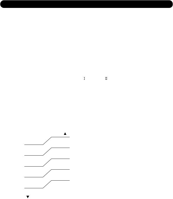
1. COOLING OPERATION
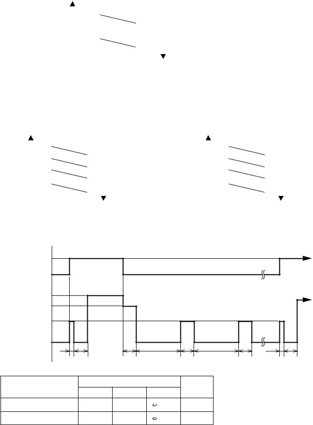
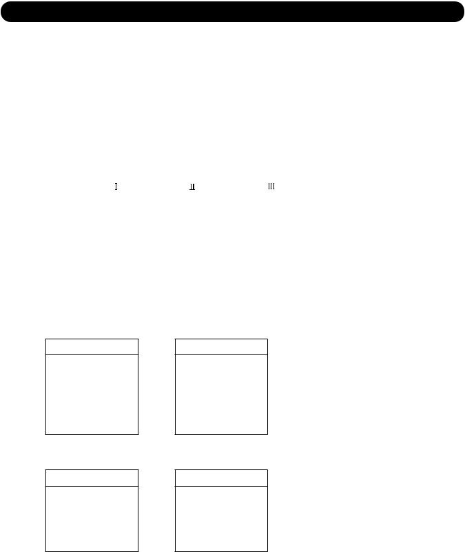
A sensor (room temperature thermistor) built in the indoor unit body will usually perceive difference or variation between a set temperature and present room temperature, and controls the operation frequency of the compressor.
*If the room temperature is 4°F(2°C) higher than a set temperature, the compressor operation frequency will attain to maximum performance.
*If the room temperature is 5°F(2.5°C) lower than a set temperature, the compressor will be stopped.
*When the room temperature is between +4°F(+2°C) to -5°F(-2.5°C) of the setting temperature, the compressor frequency is controlled within the range shown in Table1.
However, the maximum frequency is limited in the range shown in Figure1 based on the fan speed mode and the outdoor temperature.
( Table 1 : Compressor frequency range )
|
Minimum |
Maximum |
Maximum |
|
|
frequency |
frequency |
frequency |
|
AOU9RLS2 |
10rps |
76rps |
57rps |
|
AOU12RLS2 |
10rps |
76rps |
57rps |
|
AOU15RLS2 |
12rps |
91rps |
59rps |
|
When the compressor operates for 30 minutes continuously at over the maximum frequency , the maximum frequency is changed from Maximum Frequency
 to Maximum Frequency
 .
.
( Fig.1 : Outdoor temperature zone ) ( Table 2 : Limit of maximum speed based on outdoor temperature )
Outside air |
Outside air |
|||
temperature |
temperature |
|||
|
|
|
|
97°F |
|
|
|
|
|
93°F |
|
A zone |
|
(36°C) |
|
||||
|
|
90°F |
||
(34°C) |
|
|
|
|
|
|
B zone |
|
(32°C) |
86°F |
|
|
70°F |
|
(30°C) |
|
|
|
|
66°F |
|
C zone |
|
(21°C) |
|
|
54°F |
||
(19°C) |
|
|
|
|
50°F |
|
D zone |
|
(12°C) |
|
|
36°F |
||
(10°C) |
|
|
|
|
32°F |
|
E zone |
|
(2°C) |
|
|
|
||
(0°C) |
|
|
|
|
|
|
F zone |
|
|
|
|
|
|
|
|
Outdoor |
|
Indoor fan mode |
|
|
|
temp. zone |
Hi |
Me |
Lo |
Quiet |
AOU9RLS2 |
A zone |
80rps |
51rps |
43rps |
26rps |
|
B zone |
80rps |
51rps |
43rps |
26rps |
|
C zone |
80rps |
51rps |
43rps |
26rps |
|
D zone |
47rps |
35rps |
29rps |
20rps |
|
E zone |
47rps |
35rps |
29rps |
20rps |
|
F zone |
47rps |
35rps |
29rps |
20rps |
AOU12RLS2 |
A zone |
76rps |
45rps |
37rps |
29rps |
|
B zone |
76rps |
45rps |
37rps |
29rps |
|
C zone |
76rps |
45rps |
37rps |
26rps |
|
D zone |
43rps |
35rps |
26rps |
20rps |
|
E zone |
51rps |
37rps |
31rps |
22rps |
|
F zone |
51rps |
37rps |
31rps |
22rps |
AOU15RLS2 |
A zone |
91rps |
44rps |
34rps |
24rps |
|
B zone |
91rps |
44rps |
34rps |
24rps |
|
C zone |
72rps |
44rps |
34rps |
24rps |
|
D zone |
52rps |
30rps |
21rps |
18rps |
|
E zone |
63rps |
34rps |
27rps |
19rps |
|
F zone |
63rps |
34rps |
27rps |
19rps |
01-01
2. HEATING OPERATION
A sensor (room temperature thermistor) built in the indoor unit body will usually perceive difference or variation between a set temperature and present room temperature, and controls the operation frequency of the compressor.
*If the room temperature is lower by 6°F(3°C) than a set temperature, the compressor operation frequency will attain to maximum performance.
*If the room temperature is higher 5°F(2.5°C) than a set temperatire, the compressor will be stopped.
*When the room temperature is between +5°F(+2.5°C) to -6°F(-3°C) of the setting temperature, the compressor frequency is controlled within the range shown in Table3.
( Table 3 : Compressor frequency range )
|
Minimum |
Maximum |
|
frequency |
frequency |
AOU9RLS2 |
10rps |
119rps |
|
|
|
AOU12RLS2 |
10rps |
119rps |
|
|
|
AOU15RLS2 |
16rps |
140rps |
|
|
|
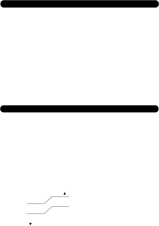
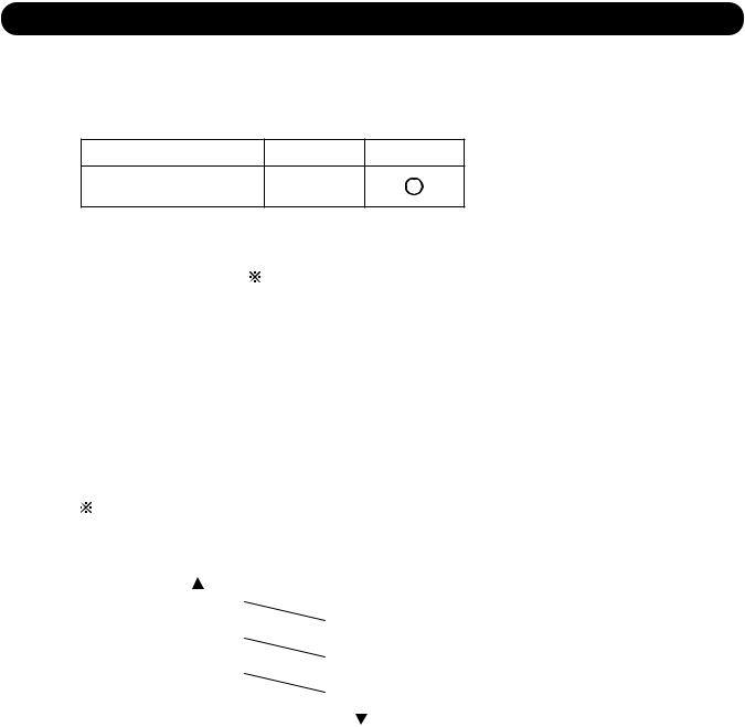
3. DRY OPERATION
The compressor frequency shall change according to the temperature, set temperature,
and room temperature variation which the room temperature sensor of the indoor unit body has detected as shown in the Table 4.
However, after the compressor is driven, the indoor unit shall run at operation frequency of 51rps (9RLS2), 51rps (12RLS2), 52rps (15RLS2) for 60 seconds.
( Table 4 : Compressor frequency in Dry mode)
|
|
Operating |
|
|
|
Operating |
|
|
|
Operating |
|
|
frequency |
|
|
|
frequency |
|
|
|
frequency |
|
|
|
|
|
|
|
|
|
|
|
AOU |
X zone |
26rps |
|
AOU |
X zone |
26rps |
|
AOU |
X zone |
24rps |
9RLS2 |
J zone |
18rps |
|
12RLS2 |
J zone |
18rps |
|
15RLS2 |
J zone |
16rps |
|
Y zone |
0rps |
|
|
Y zone |
0rps |
|
|
Y zone |
0rps |
( Fig.2 : Compressor Control based on Room Temperature )
Room |
|
|
Room |
|
temperature |
temperature |
|||
|
|
|
|
Ts+3°F |
|
|
|
|
|
Ts+1°F |
|
X zone |
|
(Ts+1.5°C) |
|
||||
|
|
|
||
|
|
|
Ts-1°F |
|
(Ts+0.5°C) |
|
|
|
|
|
|
J zone |
|
(Ts-0.5°C) |
Ts-3°F |
|
|
|
|
|
|
|
|
|
(Ts-1.5°C) |
|
Y zone |
|
|
|
|
|
|
|
|
|
|
|
|
01-02
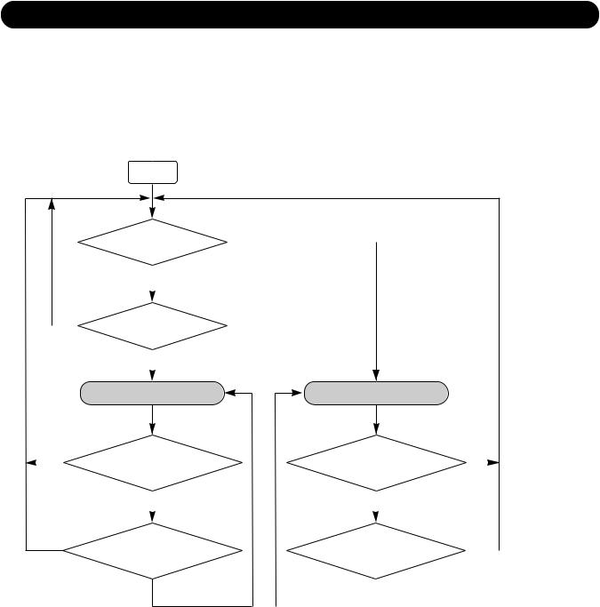
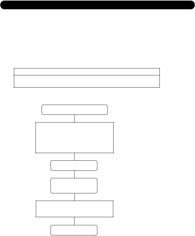
4. AUTO CHANGEOVER OPERATION
When the air conditioner is set to the AUTO mode by remote control, operation starts in the optimum mode from among the HEATING, COOLING, DRY and MONITORING modes. During operation, the optimum mode is automatically switched in accordance with temperature changes. The temperature can be set between 64°F(18°C) and 88°F(30°C) in 2°F(1°C) steps.
(Fig3 : Operation flow chart)
START
Room temp. |
|
YES |
|
>Ts+4°F(2°C)? |
|
|
|
|
NO |
TS : Setting temperature |
|
|
|||
|
|
|
|
NO |
Room temp. |
|
|
<Ts- 4°F(2°C)? |
|
|
|
YES |
|
|
|
|
|
|
HEATING OPERATION
YES |
Thermostat remains |
||
|
|
in OFF state for 6 minutes or |
|
|
|
||
|
|
longer? |
|
|
|
|
NO |
|
|
|
|
|
|
|
|
System stops
YES or operation command other than auto changeover operation?
NO
COOLING OPERATION
Thermostat remains |
YES |
|||
in OFF state for 6 minutes or |
|
|
|
|
|
|
|
||
longer? |
|
|
|
|
|
NO |
|
|
|
|
|
|
|
|
|
|
|
|
|
System stops |
|
YES |
|
|
or operation command other than |
|
|
||
auto changeover operation? |
|
|
|
|
|
NO |
|
|
|
|
|
|
|
|
|
|
|
|
|
01-03
5. INDOOR FAN CONTROL
1. Fan speed
( Table 5 : Indoor fan speed )
Operation mode |
Air flow mode |
|
Speed (rpm) |
|
|
ASU9RLS2 |
ASU12RLS2 |
ASU15RLS |
|||
|
|
||||
|
|
|
|
|
|
Heating |
Powerful |
1470 |
1470 |
1620 |
|
|
Hi |
1370 |
1370 |
1510 |
|
|
Me+ |
1260 |
1260 |
1440 |
|
|
Me |
1180 |
1180 |
1220 |
|
|
Lo |
960 |
960 |
1030 |
|
|
Quiet |
650 |
650 |
790 |
|
|
Cool air prevention |
610 |
610 |
610 |
|
|
S-Lo |
570 |
570 |
570 |
|
Cooling/ Fan |
Powerful |
1470 |
1470 |
1550 |
|
|
Hi |
1370 |
1370 |
1440 |
|
|
Me |
1120 |
1120 |
1220 |
|
|
Lo |
960 |
960 |
980 |
|
|
Quiet |
650 |
650 |
740 |
|
Dry |
|
X zone: 650 |
X zone: 650 |
X zone: 740 |
|
|
|
J zone: 610 |
J zone: 610 |
J zone: 710 |
2. FAN OPERATION
The airflow can be switched in 5 steps such as Auto, Quiet, Lo, Me, Hi, while the indoor fan only runs. When fan mode is set at [Auto], it operates on [Me] fan Speed.
3. COOLING OPERATION
Switch the airflow [Auto], and the indoor fan motor will run according to a room temperature, as shown in Figure4.
On the other hand, if switched in [Hi] [Quiet], the indoor motor will run at a constant airflow of [Cool] operation modes Quiet, Lo, Me, Hi, as shown in Table 5.
( Fig.4 : Airflow change - over ( Cooling : Auto ) )
TR-Ts > 4°F (2°C)
4°F > TR-Ts > 2°F (2°C) =(1°C)
2°F > TR-Ts (1°C)
HIGH mode
MED mode
LOW mode
When the room temperature drops
TR-Ts > 5°F =(2.5°C)
5°F > TR-Ts > 3°F (2.5°C) =(1.5°C)
3°F > TR-Ts (1.5°C)
When the room temperature rises
TR : Room temperature Ts : Setting temperature
4. DRY OPERATION
Refer to the Table 5.
During the dry mode operation, the fan speed setting can not be changed.
01-04
5. HEATING OPERATION
Switch the airflow [Auto], and the indoor fan motor will run according to a room temperature, as shown in Fig. 5
On the other hand, if switched in [Hi]  [Quiet], the indoor motor will run at a constant airflow of [Heat] operation modes Quiet, Lo, Me, High, as shown in Table 6.
( Fig.5 : Airflow change - over ( Heating : Auto ) )
|
|
When the room |
When the room |
|
|||||
|
|
temperature rises |
|
||||||
|
|
temperature drops |
|
||||||
|
|
|
|
|
|
|
|||
|
TR-Ts > -2°F |
|
|
LOW mode |
|
|
|
|
|
|
|
|
|
|
|
|
|||
|
= |
|
|
|
TR-Ts > -3°F |
|
|||
|
|
|
|
|
|
||||
|
(-1°C) |
|
|
|
|
|
|
=(-1.5°C) |
|
-2°F > TR-Ts > -4°F |
|
|
|
|
|
|
|||
(-1°C) |
=(-2°C) |
|
|
MED mode |
|
-3°F > TR-Ts > -5°F |
|||
|
-4°F > TR-Ts |
|
|
|
|
|
(-1.5°C) |
=(-2.5°C) |
|
|
|
|
|
|
|||||
|
|
|
|
|
|
|
|
|
|
|
|
|
MED+ mode |
|
-5°F > TR-Ts |
TR : Room temperature |
|||
|
(-2°C) |
|
|
|
|||||
|
|
|
|||||||
|
|
|
|
|
|
|
(-2.5°C) |
Ts : Setting temperature |
|
6. COOL AIR PREVENTION CONTROL (Heating mode)
The maximum value of the indoor fan speed is set as shown in Fig.6 based on the detected temperature by the indoor heat-exchanger sensor on heating mode.
( Fig.6 : Cool air prevension control ) |
|
|
|
|
<Powerful operation> |
||||||||||||||||||||
|
|
|
|
<Normal operation> |
|
|
|
|
|||||||||||||||||
Indoor heat exchanger |
|
|
|
|
|
|
|
Indoor heat exchanger |
|
|
|
|
|
|
|
|
|
||||||||
temperature rises |
|
|
|
Indoor heat exchanger |
temperature rises |
|
|
|
|
Indoor heat exchanger |
|||||||||||||||
|
|
|
|
|
|
|
|
|
|
|
|
|
|
|
|
|
|||||||||
108°F |
|
|
|
|
Hi |
temperature drops |
108°F |
|
|
|
|
Powerful |
|
temperature drops |
|||||||||||
|
|
|
|
|
|
|
|
||||||||||||||||||
(42°C) |
|
|
|
|
Me+ |
|
|
|
99°F |
(42°C) |
|
|
|
|
Hi |
|
|
|
|
|
99°F |
||||
102°F |
|
|
|
|
|
|
|
(37°C) |
102°F |
|
|
|
|
|
|
|
|
|
(37°C) |
||||||
(39°C) |
|
|
Lo |
|
|
|
|
93°F |
(39°C) |
|
|
Lo |
|
|
|
|
|
|
96°F |
||||||
99°F |
|
|
|
|
|
|
|
|
|
99°F |
|
|
|
|
|
|
|
|
|
|
|
||||
|
|
|
|
|
|
|
|
(34°C) |
|
|
|
|
|
|
|
|
|
|
(34°C) |
||||||
|
|
|
|
|
|
|
|
|
|||||||||||||||||
(37°C) |
|
|
Cool air |
|
|
|
|
90°F |
(37°C) |
|
|
Cool air |
|
|
|
|
|
|
90°F |
||||||
|
|
|
|
|
|
|
|
|
|
|
|
|
|
|
|
|
|
|
|
|
|
||||
86°F |
|
|
|
prevention |
|
|
|
(32°C) |
86°F |
|
|
|
prevention |
|
|
|
|
|
(32°C) |
||||||
(30°C) |
|
|
S-Lo |
|
|
|
82°F |
(30°C) |
|
|
S-Lo |
|
|
|
|
|
82°F |
||||||||
|
|
|
|
|
|
|
|
|
|
|
|
|
|
|
|
|
|
|
|
||||||
|
|
|
|
|
|
|
|
|
|
|
|
|
|
|
|
|
|
||||||||
|
|
|
|
|
|
|
|
|
|
|
(28°C) |
|
|
|
|
|
|
|
|
|
|
|
|
|
(28°C) |
7. MOISTURE RETURN PREVENTION CONTROL (Cooling mode& Dry mode)
Switch the airflow [Auto] at cooling mode, and the indoor fan motor will run as shown in Fig.7. ( Fig.7 : Indoor fan control )
Compressor ON
OFF
Indoor fan
Setting air flow
Indoor fan
(as shown in Table 6)
S-Lo |
|
|
|
|
|
|
|
|
|
OFF |
|
|
|
|
|
|
|
|
|
10 |
30 |
60 |
|
180 |
60 |
180 |
60 |
10 |
30 |
( Table 6 : Indoor fan speed ) |
|
|
|
|
|
|
|
(sec) |
|
|
|
|
|
|
|
|
|
||
|
|
Dry |
|
|
Cooling |
|
|
|
|
|
X zone |
J zone |
|
Y zone |
|
|
|
|
|
|
|
|
|
|
|
|
|||
ASU9 /12RLS2 |
650rpm |
610rpm |
0 |
570rpm |
650rpm |
|
|
|
|
ASU15RLS2 |
740rpm |
710rpm |
0 |
570rpm |
740rpm |
|
|
|
|
01-05
6. OUTDOOR FAN CONTROL
1. Outdoor Fan Motor
Following table shows the type of the outdoor fan motor. The control method is different between AC motor and DC motor.
( Table 7 : Type of Motor )
AC Motor |
DC Motor |
AOU9 / 12 / 15RLS2
2. Fan Speed
|
( Table 8 : Outdoor fan speed ) |
|
|
(rpm) |
|||||||||||
|
|
|
|
Zone |
|
|
|
Cooling |
|
Heating |
Dry |
||||
|
|
|
|
Y |
|
1050/ 870/ 720/ 590/ 530 |
|
|
|||||||
|
AOU9RLS2 |
Z |
|
870/530/300 |
|
|
|
1100/ 870/ 780/ 720/ 590/ 480 |
530 |
||||||
|
F |
|
300/ 250 |
|
|
|
|||||||||
|
|
|
|
|
|
|
|
|
|
||||||
|
|
|
|
G |
|
250/ 200 |
|
|
|
|
|
||||
|
|
|
|
Y |
|
1050/ 870/ 720/ 590/ 530 |
|
|
|||||||
|
AOU12RLS2 |
Z |
|
870/530/300 |
|
|
|
1100/ 870/ 780/ 720/ 590/ 480 |
530 |
||||||
|
F |
|
300/ 250 |
|
|
|
|||||||||
|
|
|
|
|
|
|
|
|
|
||||||
|
|
|
|
G |
|
250/ 200 |
|
|
|
|
|
||||
|
|
|
|
Y |
|
1050/ 870/ 720/ 530 |
|
|
|||||||
|
AOU15RLS2 |
Z |
|
870/ 530/ 300 |
|
1100/ 1000/ 780/ 720/ 590/ 480 |
530 |
||||||||
|
F |
|
300 |
|
|
|
|||||||||
|
|
|
|
|
|
|
|
|
|
||||||
|
|
|
|
G |
|
250/ 200 |
|
|
|
|
|
||||
|
Refer to Fig.8 |
|
|
|
|
|
|
|
|
|
|
|
|
||
( Fig.8 : Outside air temperature zone selection ) |
|
|
|
||||||||||||
|
Outside air |
|
|
|
|
|
|
Outside air |
|
||||||
|
temperature |
|
|
D zone |
temperature |
|
|||||||||
|
70°F |
|
|
|
|
|
|
|
|||||||
|
(21°C) |
|
|
|
F zone |
|
|
|
|
66°F |
|
||||
|
|
|
|
|
|
|
|
|
|
|
|||||
|
54°F |
|
|
|
|
|
|
(19°C) |
|
||||||
|
(12°C) |
|
|
|
G zone |
|
|
|
|
|
50°F |
|
|||
|
|
|
|
|
|
|
|
|
|
|
|
||||
|
36°F |
|
|
|
|
|
|
|
(10°C) |
|
|||||
|
(2°C) |
|
|
|
H zone |
|
|
|
|
|
32°F |
|
|||
|
|
|
|
|
|
|
|
|
|
|
|
||||
|
|
|
|
|
|
|
|
|
( 0°C) |
|
|||||
|
|
|
|
|
|
|
|||||||||
|
|
|
|
|
|
|
|
|
|
|
|
|
|
|
|
*The outdoor fan speed mentioned above depends on the compressor frequency.
(When the compressor frequency increases, the outdoor fan speed also changes to the higher speed. When the compressor frequency decreases, the outdoor fan speed also changes to the lower speed.)
*After the defrost control is operated on the heating mode, the fan speed keeps at the higher speed as table 9 without relating to the compressor frequency.
( Table 9 : Outdoor fan speed after the defrost )
AOU9RLS2 |
1100rpm |
AOU12RLS2 |
1100rpm |
AOU15RLS2 |
1100rpm |
01-06

7. LOUVER CONTROL
1. VERTICAL LOUVER CONTROL
(Function Range)
Each time the button is pressed, the air direction range will change as follow: Fig.9 : Air Direction Range
Types of Air flow Direction Setting:
, |
, |
|
: During Cooling/Dry modes |
, |
, |
, |
: During Heating |
The Remote Controller's display does not change.
1
2
3
4
5
6
7
 Use the air direction adjustments within the ranges shown above.
 The vertical airflow direction is set automatically as shown, in accordance with the type of operation selected. Cooling / Dry mode
  Horizontal flow
Heating mode |
Downward flow |
 During AUTO mode operation, for the first a few minutes after beginning operation, air-flow will be horizontal 1; the air direction cannot be adjusted during this period.
The air flow direction setting will temporarily become 1 when the temperature of the air -flow is low at the start of the Heating mode.
2. ADJUST THE RIGHT-LEFT LOUVERS
 Move the Right-Left louvers to adjust air flow in the direction you prefer.
Right-Left Louvers
Knob
Knob (2 places)
2. SWING OPERATION
To select Vertical Airflow Swing Operation
When the swing signal is received from the remote controller, the vertical louver starts to swing. (Table10 : Swinging Range)
Range
Cooling / Dry mode
Fan mode (
 )
)
Heating mode |
) |
Fan mode ( |
 The SWING operation may stop temporarily when the air conditioner’s fan is not operating, or when operating at very low speeds.
To select Horizontal Airflow Swing Operation
(No function)
01-07
8.COMPRESSOR CONTROL
1.OPEARTION FREQUENCY RANGE
The operation frequency of the compressor is different based on the operation mode as shown in the Table 11.
(Table 11 : Compressor frequency range)
|
Cooling / Dry |
Heating |
||
|
|
|
|
|
|
Minimum |
Maximum |
Minimum |
Maximum |
|
|
|
|
|
AOU9RLS2 |
10rps |
76rps |
10rps |
119rps |
AOU12RLS2 |
10rps |
76rps |
10rps |
119rps |
AOU15RLS2 |
12rps |
91rps |
16rps |
140rps |
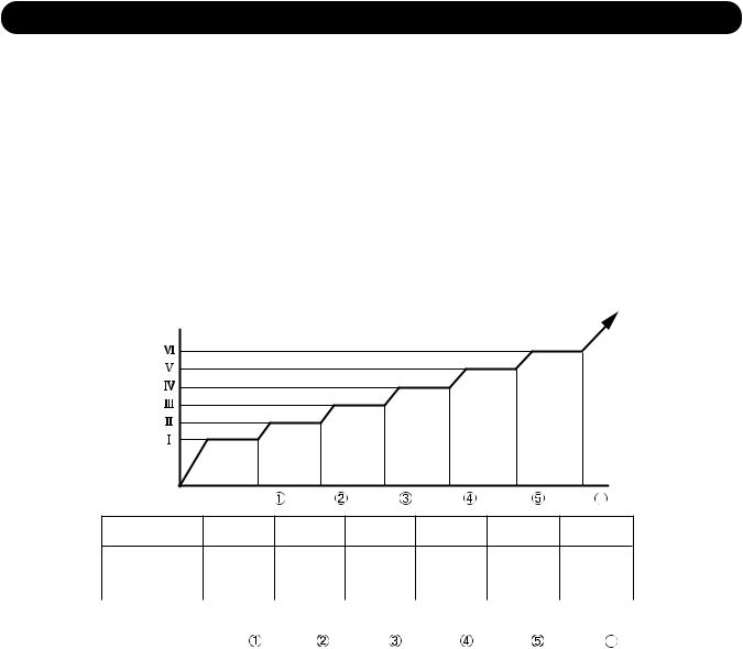
2.OPEARTION FREQUENCY CONTROL AT NORMAL START UP
The compressor frequency soon after the start-up is controlled as shown in the Fig.10
(Fig.10 : Compressor control at start-up)
Frequency |
|
|
|
|
|
|
Frequency |
|
|
|
|
|
|
Frequency |
|
|
|
|
|
|
Frequency |
|
|
|
|
|
|
Frequency |
|
|
|
|
|
|
Frequency |
|
|
|
|
|
|
(Frequency) |
Time |
Time |
Time |
Time |
Time |
Time 6 |
|
|
|
|
|
|
Frequency Frequency
 Frequency
 Frequency
 Frequency
 Frequency
AOU9RLS2 |
40rps |
57rps |
72rps |
80rps |
101rps |
110rps |
|
AOU12RLS2 |
|||||||
|
|
|
|
|
|
||
AOU15RLS2 |
40rps |
59rps |
72rps |
80rps |
101rps |
110rps |
|
(Time) |
|
|
|
|
|
|
|
|
Time |
Time |
Time |
Time |
Time |
Time 6 |
|
|
|
|
|
|
|
|
|
AOU9RLS2 |
|
|
|
|
|
|
|
AOU12RLS2 |
80sec |
110sec |
140sec |
200sec |
350sec |
410sec |
|
AOU15RLS2 |
|
|
|
|
|
|
3.LIMITATION OF COMPRESSOR FREQUENCY BY OUTDOOR TEMPERATURE
The minimum compressor frequency is limited by outdoor temperature as shown in the Table12.
(Table12 : Limitation of Compressor Frequency)
[ Cooling/ Dry ]
|
|
10°C |
|
14°C |
|
40°C |
|
|
|
||||
|
|
Under |
|
Over |
Under |
Over |
Under |
Over |
|
|
|
||
AOU9RLS2 |
35rps |
|
18rps |
|
10rps |
|
15rps |
|
|
|
|||
AOU12RLS2 |
|
|
|
|
|
|
|||||||
|
|
|
|
|
|
|
|
|
|
|
|
||
[ Heating ] |
|
|
|
|
|
|
|
|
|
|
|
|
|
|
|
- 5°C |
|
3°C |
|
7°C |
|
18°C |
|||||
|
|
Under |
|
Over |
Under |
Over |
Under |
Over |
Under |
Over |
|||
AOU9RLS2 |
35rps |
|
29rps |
|
18rps |
|
10rps |
|
16rps |
||||
AOU12RLS2 |
|
|
|
|
|||||||||
|
|
|
|
|
|
|
|
|
|
|
|
||
[ Cooling/ Dry ] |
|
|
|
|
|
|
|
|
|
|
|
|
|
|
|
0°C |
|
|
10°C |
|
40°C |
|
|
|
|||
|
|
Under |
|
Over |
Under |
Over |
Under |
Over |
|
|
|
||
AOU15RLS2 |
24rps |
|
18rps |
|
12rps |
|
16rps |
|
|
|
|||
[ Heating ] |
|
|
|
|
|
|
|
|
|
|
|
|
|
|
|
7°C |
|
|
14°C |
|
|
|
|
|
|
||
|
|
Under |
|
Over |
Under |
Over |
|
|
|
|
|
|
|
AOU15RLS2 |
24rps |
|
18rps |
|
16rps |
|
|
|
|
|
|
||
01-08
9. TIMER OPEARTION CONTROL
9-1 WIRELESS REMOTE CONTROLLER
The Table 13 shows the available timer setting based on the product model. ( Table 13 : Timer Setting )
ON TIMER / OFF TIMER PROGRAM TIMER |
SLEEP TIMER WEEKLY TIMER |
ASU9/ 12/ 15RLS2
1. OPEARTION FREQUENCY RANGE
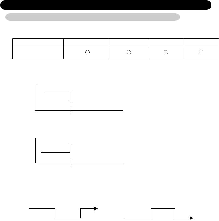
 OFF timer : When the clock reaches the set time, the air conditioner will be turned off.
Operation mode
 Stop mode
Set time of timer
 ON timer : When the clock reaches the set time, the air conditioner will be turned on.
 Operation mode
Stop mode
Set time of timer
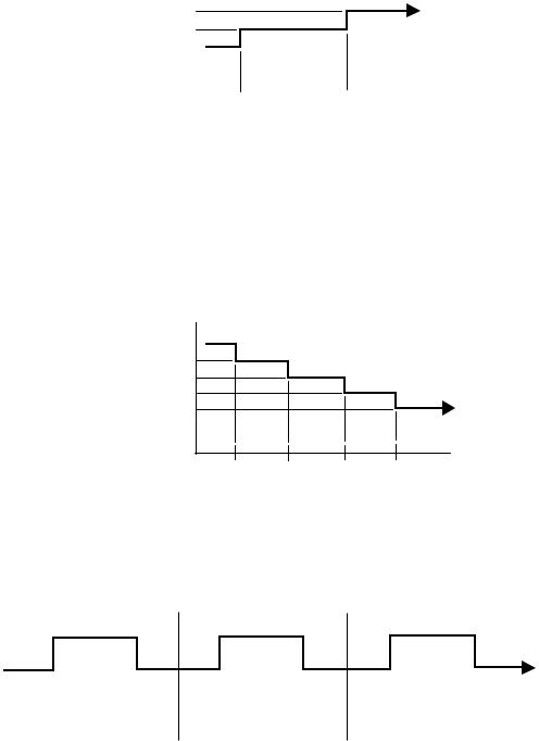
2. PROGRAM TIMER
 The program timer allows the OFF timer and ON timer to be used in combination one time.
Operation mode |
Operation mode |
Operation mode |
|||||||
|
Stop mode |
Stop mode |
|
Stop mode |
|||||
|
|
|
|
|
|
|
|
|
|
|
|
|
|
|
|
|
|
|
|
|
|
|
|
|
|
|
|
|
|
Set time |
Set time |
Set time |
Set time |
||||||
 Operation will start from the timer setting (either OFF timer or ON timer) whichever is closest to the clock's current timer setting.
The order of operations is indicated by the arrow in the remote control unit's display.  SLEEP timer operation cannot be combined with ON timer operation.
01-09
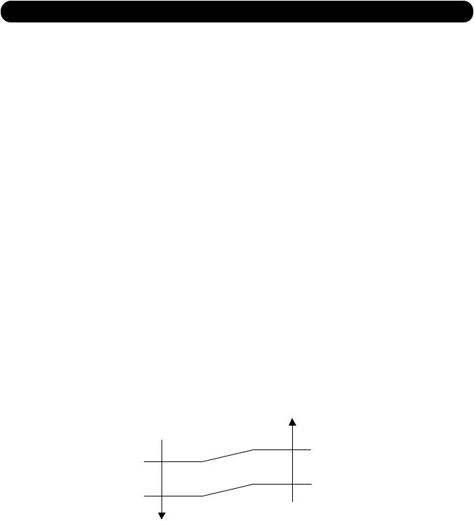
3. SLEEP TIMER
If the sleep is set, the room temperature is monitored and the operation is stopped automatically. If the operation mode or the set temperature is change after the sleep timer is set, the operation is continued according to the changed setting of the sleep timer from that time ON.
In the cooling operation mode
When the sleep timer is set, the setting temperature is increased 2°F(1°C). It increases the setting temperature another 2°F(1°C) after 1 hour.
After that, the setting temperature is not changed and the operation is stopped at the time of timer setting.
Set temperature rises ( Ts : Set temperature )
+4°F (2°C) |
|
|
|
|
|
+2°F (1°C) |
|
|
|
Stop of operation |
|
Ts |
|
|
|
|
|
|
|
|
|
|
|
|
|
|
|
|
|
|
|
|
|
|
|
|
Set |
60min |
|||
In the heating operation mode |
|
|
|
||
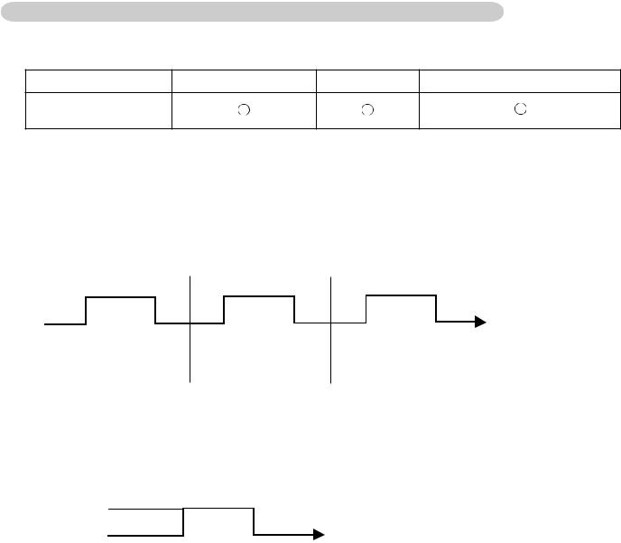
When the sleep timer is set, the setting temperature is decreased 2°F(1°C). It decreases the setting temperature another 2°F(1°C) every 30 minutes.
Upon lowering 8°F(4°C) the setting temperature is not changed and the operation stops at the time of timer setting.
Set temperature lowers ( Ts : Set temperature )
Ts
-2°F (-1°C)
-4°F (-2°C)
-6°F (-3°C)
-8°F (-4°C)
Stop of operation
Set 30min 30min 30min
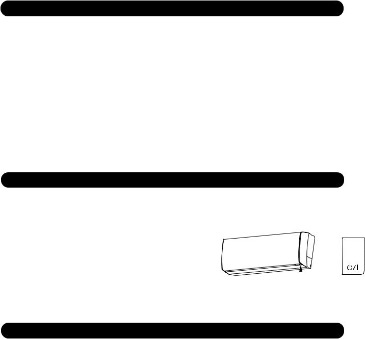
4. WEEKLY TIMER
This timer function can set operation times of the each day of the week.
All days can be set together,the weekly timer can be used to repeat the timer setting for all of the days.
|
ON |
|
OFF |
ON |
OFF |
ON |
OFF |
||||||||||||
|
|
|
|
|
|
|
|
|
|
|
|
|
|
||||||
|
|
|
Setting day |
|
|
|
|
Setting day |
|
|
|
Setting day |
|
||||||
|
|
|
|
|
|
|
|
|
|
|
|
|
|
|
|
|
|
|
|
|
|
|
|
|
|
|
|
|
|
|
|
|
|
|
|
|
|
|
|
|
|
|
|
|
|
|
|
|
|
|
|
|
|
|
|
|
|
|
|
|
Set time |
|
Set time |
|
|
|
|
|
|
|
|
|
|
|
|
||||
01-10
9-2 WIRED REMOTE CONTROLLER (OPTION)
The Table14 shows the available timer setting based on the product model. ( Table14 : Timer Setting )
ON TIMER / OFF TIMER WEEKLY TIMER TEMPERATURE SET BACK TIMER
ASU9/ 12/ 15RLS2
1. ON TIMER / OFF TIMER
Same to 9-1 1.ON TIMER / OFF TIMER and shown in those.
2. WEEKLY TIMER
This timer function can set operation times of the each day of the week.
All days can be set together,the weekly timer can be used to repeat the timer setting for all of the days.
|
ON |
|
OFF |
ON |
OFF |
ON |
OFF |
||||||||||||
|
|
|
|
|
|
|
|
|
|
|
|
|
|
||||||
|
|
|
Setting day |
|
|
|
|
Setting day |
|
|
|
Setting day |
|
||||||
|
|
|
|
|
|
|
|
|
|
|
|
|
|
|
|
|
|
|
|
|
|
|
|
|
|
|
|
|
|
|
|
|
|
|
|
|
|
|
|
|
|
|
|
|
|
|
|
|
|
|
|
|
|
|
|
|
|
|
|
|
Set time |
|
Set time |
|
|
|
|
|
|
|
|
|
|
|
|
||||
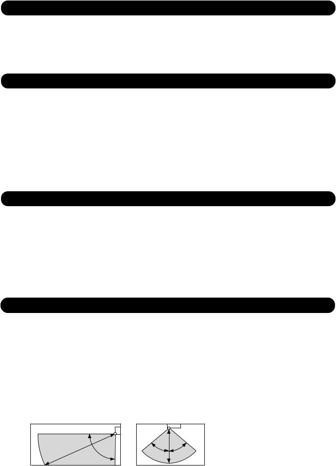
3. TEMPERATURE SET BACK TIMER
This timer function can change setting temperature of setting operation times of the each day of the week. This can be together with other timer setting.
|
|
|
ON |
|
OFF |
|||
|
Set back tmp. |
|
|
|||||
|
|
|
|
|
|
|
|
|
|
Normal tmp. |
|
|
|
|
|
|
|
|
|
|
|
|
|
|
|
|
|
|
|
|
|
|
|
|
|
|
|
|
|
|
|
|
|
|
|
|
|
|
|
|
|
||
|
|
|
Set time |
|
Set time |
|
||
01-11

10. ELECTRONIC EXPANSION VALVE CONTROL
The most proper opening of the electronic expansion valve is calculated and controlled under the present operating condition based on the Table15.
The compressor frequency, the detected temperature by the discharge temperature sensor,
the indoor heat exchanger sensor, the outdoor heat exchanger sensor, and the outdoor temperature sensor. ( Table15 : The pulse range of the electronic expansion valve control )
|
Operation mode |
Pulse range |
|
AOU9RLS2 |
Cooling / Dry mode |
Between 60 to 480 pulses. |
|
|
|
||
AOU12RLS2 |
Heating mode |
Between 45 to 480 pulses. |
|
|
|||
|
|
|
|
AOU15RLS2 |
Cooling / Dry mode |
Between 60 to 480 pulses. |
|
Heating mode |
|||
|
|
 The expansion valve is set at 480 pulses 110seconds after the compressor had stopped.
 Initialization will start after 24 hours pass from the last initialization, and the compressor stops
 At the time of supplying the power to the outdoor unit, the initialization of the electronic expansion valve is operated (528 pulses are input to the closing direction).
11. TEST OPERATION CONTROL
[ Operation method ]
The outdoor unit, may not operate, depending on the room temperature.
In this case, keep on pressing the MANUAL AUTO button of the indoor unit for more than 10 seconds. The Operation lamp and Timer lamp will begin to flash simultaneously during cooling test run.
Then, heating test run will begin in about 3 minutes when HEAT is selected by the remote control operation. (When the air conditioner is running by pressing the test run button, the Operation lamp and Timer lamp will simultaneously flash slowly.)
[ Release ]
Perform the test operation for 60 minutes.
Pressing the MANUAL AUTO button of the indoor unit for more than 3 seconds.
[ Using the Wired remote control (Option) ]
If the Operation lamp is on, press the START/STOP button to turn it off.
Press the MODE and the FAN buttons at the same time for more than two seconds to start the test operation.
The operation lamp will light up and "o1" will be displayed on the set temperature display.
[ Release ]
Perform the test operation for 60 minutes.
Pressing the START/STOP button will stop the test operation.
12. PREVENT TO RESTART FOR 3 MINUTES ( 3 MINUTES ST )
The compressor won't enter operation status for 2 minutes and 20 seconds after the compressor is stopped, even if any operation is given.
13. FOUR-WAY VALVE EXTENSION SELECT
At the time when the air conditioner is switched from the cooling mode to heating mode, the compressor is stopped, and the four-way valve is switched in 2 minutes and 20 seconds later after the compressor stopped.
01-12
14. AUTO RESTART
When the power was interrupted by a power failure, etc. during operation, the operation contents at that time are memorized and when power is recovered, operation is automatically started with the memorized operation contents.
When the power is interrupted and recovered during timer operation, since the timer operation time is shifted by the time the power was interrupted, an alarm is given by blinking (7 sec ON/2 sec OFF) the indoor unit body timer lamp.
[ Operation contents memorized when the power is interrupted ]
 Operation mode
 Set temperature
 Set air flow
 Timer mode and set time (set by wireless remote controller)
 Set air flow Direction
 Swing
Swing
 ECONOMY operation
 10°C HEAT operationOutdoor low noise operation
  Human sensor
15. MANUAL AUTO OPERATION (Indoor unit body operation)
When the remote control is lost or battery power dissipated, this function will work without the remote control. When MANUAL AUTO button is set more than 3seconds and less than 10seconds, MANUAL AUTO OPERATION will be started as shown in Table16.To stop operation, press the MANUAL AUTO button for 3seconds.
(Table16 : MANUAL AUTO OPERATION)
|
Manual auto operation |
OPERATION MODE |
Auto changeover |
FAN CONT. MODE |
Auto |
TIMER MODE |
Continuous (No timer setting available) |
SETTING TEMP. |
75°F(24°C) |
SETTING LOUVER |
Standard |
SWING |
OFF |
ECONOMY |
OFF |
|
AUTO |
MANUAL AUTO |
Press and hold MANUAL |
||
button for 3 ~ 10seconds |
button |
|
16. FORCED COOLING OPERATION (TEST OPERATION)
When FORCED COOLING OPERATION is set, the operation is controlled as shown in Table17. ( Table17 : FORCED COOLING OPERATION )
|
Forced cooling operation |
OPERATION MODE |
Cooling |
FAN CONT. MODE |
Hi |
TIMER MODE |
- |
SETTING TEMP. |
Room Temp is not controlled |
SETTING LOUVER |
Horizontal |
|
(It is changed follow as setting of remote controller) |
SWING |
OFF |
ECONOMY |
- |
 Forced cooling operation is started when press MANUAL AUTO button for 10 seconds or more.
 During the forced cooling operation, it operates regardless of room temperature sensor.
 Operation LED and timer LED blink at the same time during the forced cooling operation.
They blink for 1 second ON and 1 second OFF on both operation LED and timer LED (same as test operation).
 Forced cooling operation is released after 60 minutes of starting operation or pressing MANUAL AUTO button for 3 seconds.
01-13
17. COMPRESSOR PREHEATING
When the outdoor heat exchanger temperature is lower than 41°F(5°C) and the all operation has been stopped for 30 minutes, power is applied to the compressor and the compressor is heated. (By heating the compressor, warm air is quickly discharged when operation is started.)
When operation was started, and when the outdoor heat exchanger temperature rises to 44.6°F(7°C) or greater, preheating is ended.
18. MIN. (MINIMUM) HEAT OPERATION
MIN. HEAT OPERATION performs as below when pressing MIN. HEAT button or Weekly timer setting on the remote controller.
( Table 18 : MIN. HEAT OPERATION )
Mode |
Heating |
|
Setting temperature |
50°F(10°C) |
|
Fan mode |
Auto |
|
LED display |
Economy |
|
Defrost operation |
Operate as normal |
|
|
|
|
19. ECONOMY OPERATION
The ECONOMY operation functions by pressing ECONOMY button on the remote controller.
At the maximum output, ECONOMY Operation is approximately 70% of normal air conditioner operation for cooling and heating.
The ECONOMY operation is almost the same operation as below settings. ( Table 19 )
Mode |
Cooling/ Dry |
Heating |
|
|
|
Target temperature |
Setting temp.+2°F(+1°C) |
Setting temp.-2°F(-1°C) |
|
|
|
20 . HUMAN SENSOR CONTROL
The HUMAN SENSOR functions by pressing SENSOR button on the remote controller. When the sensor detects that there is no one in the room for 20 minutes or more,
it automatically changes the operation as below settings.
When someone comes back into the room, the human sensor will detect this, and automatically revert to the original settings.
( Table 20 )
Mode |
Cooling/ Dry |
Heating |
|
|
|
Target temperature |
Setting temp.+4°F(+2°C) |
Setting temp.-8°F(-4°C) |
|
|
|
( Application range )
Vertical angle 90°(Side view)
6 m |
90° |
Horizontal angle 100°(Top view)
|
6 m |
50° |
50° |
 The sensor unit should detect when the human body (estimate: 100cmX30cm) or the object which has more than 39°F(4°C) temp, difference from the background and are crossed with 1.0m/s speed in front of the sensor unit.
01-14

21. OUTDOOR UNIT LOW NOISE OPERATION
The OUTDOOR UNIT LOW NOISE Operation functions by pressing OUTDOOR UNIT LOW NOISE button on the remote controller.
This operation stops the PFC control, and changes the Current release operation/release value.
OUTDOOR UNIT LOW NOISE Operation mode can be used during cooling, heating and automatic operation. It can not be used in Fan and Dry mode
( Table 21 )
|
Control / Release |
|
|
|
|
Current release |
3.5A / 3.0A |
|
operation/release value |
||
|
22. POWERFUL OPERATION
The POWERFUL OPERATION functions by pressing POWERFUL button on the remote controller. The indoor unit & outdoor unit will operate at maximum power as shown in Table22.
(Table22)
|
Powerful operation |
COMPRESSOR FREQUENCY |
Maximum |
FAN CONT. MODE |
Powerful |
|
|
SETTING LOUVER |
Cooling/ Dry : 3, Heating : 5 |
Release Condition is as follows. [Cooling / Dry]
- Room tenperature < Setting temperature -3°F(- 1.5°C) or Operation time has passed 20 minutes.
=
[Heating]
- Room tenperature > Setting temperature +3.5°F(+1.5°C) or Operation time has passed 20 minutes.
=
23. BASE HEATER OPERATION
The base heater is operated as shown in Figure 11.
( Fig.11 : Base heater control )
When outdoor |
|
|
When outdoor |
|||
temperature drops |
|
|
temperature rises |
|||
|
|
|
OFF |
|
|
41°F |
|
|
|
|
|
||
|
|
|
|
|
|
|
35.6°F |
|
|
|
|
(5°C) |
|
|
|
|
|
|
||
(2°C) |
|
|
ON |
|
|
|
|
|
|
|
|
|
|
 When the compressor stops, Base heater is OFF.
 When the outdoor fan motor stops, Base heater is OFF.
 In the cooling mode, Base heater is OFF.
 In the defrost operation, Base heater maintains the same status as before the compressor stops.
01-15
24. DEFROST OPERATION CONTROL
1.CONDITION OF STARTING THE DEFROST OPERATION
The defrost operation starts as shown in the following Table 23.
(Table 23 : Condition of starting Defrost Operation)
Normal defrost |
Compressor integrating operation time |
|||
|
|
|
||
|
|
Less than 25 minutes (9/12RLS2) |
More than 25 minutes (9/12RLS2) |
|
|
|
Less than 40 minutes (15RLS2) |
More than 40 minutes (15RLS2) |
|
|
|
|
|
|
|
|
Does not operate |
Outdoor heat exchanger temp. < 1.4°F(-17°C) |
|
|
|
= |
|
|
|
|
|
(at outside air temp. > 14°F(-10°C) |
|
|
|
|
= |
|
|
|
|
Outdoor heat exchanger temp. < Outside air temp.- 44.6°F(7°C) |
|
|
|
|
= |
|
|
|
|
or Outdoor heat exchanger temp. < -13°F(- 25°C) |
|
|
|
|
= |
|
|
|
|
(at outside air temp. < 14°F(-10°C) |
|
|
|
|
|
|
|
|
|
|
|
Integrating defrost |
Compressor integrating operation time |
|
||
|
|
|
||
|
|
More than 210 minutes |
Less than 10 minutes |
|
|
|
(For continuous operation) |
( For intermittent operation ) |
|
|
|
Outdoor heat exchanger |
OFF count of the compressor |
|
|
|
temperature below 26.6°F(-3°C) |
40 times |
|
|
|
|
|
|
 If the compressor continuous operation time is less than 10 minutes, the OFF number of the compressor is counted.
If any defrost operated, the compressor OFF count is cleared.
2. CONDITION OF THE DEFROST OPERATION COMPLETION
Defrost operation is released when the conditions become as shown in Table 24. (Table 24 : Defrost Release Condition)
Release Condition
Outdoor heat exchanger temperature sensor value is higher than 60.8°F(16°C) or
Compressor operation time has passed 15 minutes.
01-16
3. Defrost Flow Chart
The defrosting shall proceed by the integrating operation time, outdoor temperature and outdoor heat exchanger temperature as follows.
|
|
|
|
|
Heating operation start : Compressor ON |
|
|
|
|
||||||
|
|
|
|
|
|
|
|
|
(Not defrosted for 10 minutes) |
||||||
|
|
|
|
|
|
|
|
|
|||||||
|
|
|
|
|
|
|
|
|
|
|
|
|
|
|
|
|
|
Normal |
defrost |
|
|
Integrating |
|
defrost |
|||||||
|
|
|
|
|
|
|
|
|
|
|
|
|
|
|
|
Outside air temp. > 14°F |
Outside air |
temp. < 14°F |
Intermittent |
operation |
|
Continuous |
operation |
||||||||
|
|
= (-10°C) |
|
|
(-10°C) |
|
|
|
|
|
|
|
|
||
|
Outdoor HEX temp. |
|
|
Outdoor HEX temp. |
|
|
Compressor |
|
|
Compressor |
|
|
|||
|
Below 1.4°F(-17°C) |
|
|
< Outside air temp. |
|
|
OFF count : |
|
|
integrating |
|
|
|||
|
|
|
= |
|
|
|
40 times |
|
|
operation: |
|
|
|||
|
|
|
|
|
-44.6°F(7°C) |
|
|
|
|
|
|
||||
|
|
|
|
|
or |
|
|
(Less than 10min.) |
|
|
Over 210 |
min. |
|
||
|
|
|
|
|
Outdoor HEX temp. |
|
|
|
|
|
|
|
|
|
|
|
|
|
|
|
|
|
|
|
|
|
|
|
|
||
|
|
|
|
|
Below - 25°C |
|
|
|
|
|
|
|
|
|
|
|
|
|
|
|
|
|
|
|
|
|
|
|
|
|
|
|
|
|
|
|
|
|
|
|
|
|
|
|
Outdoor |
|
|
|
|
|
|
|
|
|
|
|
|
|
|
|
heat exchanger |
|
|
|
|
|
|
|
|
|
|
|
|
|
|
|
temperature: |
|
|
|
|
|
|
|
|
|
|
|
|
|
|
|
Below 26.6°F(-3°C) |
|
|
|
|
|
|
|
|
|
|
|
|
|
|
|
|
|
|
|
|
|
|
|
|
|
|
|
|
|
|
|
|
|
|
Defrost start
Defrost Indicator: [Operation lamp]
7 sec ON / 2 sec OFF
Outdoor fan : OFF Compressor speed : 0 rps EEV : 480pulse
4-way valve : OFF
Compressor speed : 70rps (9/12RLS2) 80rps (15RLS2)
Outdoor HEX temp.: Over 60.8°F(16°C) or
Compressor ON time: Maximum 15 minutes
Defrost end
01-17
25. OFF DEFROST OPEARTION CONTROL
When operation stops in the [Heating operation] mode, if frost is adhered to the outdoor unit heat exchanger, the defrost operation will proceed automatically. In this time, if indoor unit operation lamp flashes slowly (7 sec ON / 2 sec OFF), the outdoor unit will allow the heat exchanger to defrost, and then stop.
1. OFF DEFROST OPERATION CONDITION
In heating operation, the outdoor heat exchanger temperature is less than 24.8°F(- 4°C), compressor continuous operation more than 10 minutes, and
compressor operation integrating time lasts for more than 30 minutes.
2. OFF DEFROST END CONDITION
Release Condition
Outdoor heat exchanger temperature sensor value is higher than 60.8°F(16°C) or Compressor operation time has passed 15 minutes.
OFF Defrost Flow Chart
Heating operation stop
 Outdoor heat exchanger temperature :
Below 24.8°F(- 4°C)
 Compressor continuous operation :
Over 10 minutes
 Compressor integrating operation :
Over 30 minutes
Defrost start
Defrost Indicater: [Operation lamp]
7 sec ON / 2 sec OFF
Outdoor heat exchanger temperature:
Over 60.8°F(16°C) or
Compressor ON time: Over 15 minutes
Defrost end
01-18
26. VARIOUS PROTECTIONS
1.DISCHARGE GAS TEMPERATURE OVERRISE PREVENSION CONTROL
The discharge gas thermosensor (discharge thermistor : Outdoor side) will detect discharge gas temperature.
When the discharge temperature becomes higher than Temperature  , the compressor frequency is decreased 20rps, and it continues to decrease the frequency for 20rps every 120 seconds until the temperature becomes lower than Temperature
 .
.
When the discharge temperature becomes lower than Temperature , the protection control of the compressor frequency will be released.
When the discharge temperature becomes higher than Temperature , the compressor is stopped and the indoor unit LED starts blinking.
( Table 25 : Discharge temperature over rise prevension control / Release temperature )
Temperature |
Temperature |
Temperature |
219.2°F |
213.8°F |
230°F |
(104°C) |
(101°C) |
(110°C) |
|
|
|
2.CURRENT RELEASE CONTROL
The compressor frequency is controlled so that the outdoor unit input current does not exceed the current limit value that was set up with the outdoor temperature.
The compressor frequency returns to the designated frequency of the indoor unit at the time when the frequency becomes lower than the release value.
( Table 26 : Current release operation value / Release value )
[ Heating ]
AOU9 / 12RLS2
OT (Control / Release)
62.6°F |
7.0A / 6.5A |
|
|
||
(17°C) |
9.0A / 8.5A |
|
53.6°F |
||
|
||
(12°C) |
10.0A / 9.5A |
|
41°F |
|
|
(5°C) |
10.0A / 9.5A |
OT : Outdoor Temperature
[ Heating ]
AOU15RLS2
OT (Control / Release)
62.6°F |
7.0A / 6.5A |
|
|
||
(17°C) |
9.0A / 8.5A |
|
53.6°F |
||
|
||
(12°C) |
11.0A / 10.5A |
|
41°F |
|
|
(5°C) |
13.0A / 12.5A |
OT : Outdoor Temperature
[ Cooling ]
AOU9 / 12RLS2
OT (Control / Release)
114.8°F |
4.5A / 4.0A |
|
(46°C) |
|
6.0A / 5.5A |
104°F |
|
|
|
|
|
(40°C) |
8.5A / 8.0A |
|
OT : Outdoor Temperature
[ Cooling ]
AOU15RLS2
OT (Control / Release)
114.8°F 4.5A / 4.0A
(46°C) |
6.0A / 5.5A |
|
104°F |
||
|
||
(40°C) |
9.0A / 8.5A |
|
|
OT : Outdoor Temperature
01-19
 Loading...