


SPLIT TYPE
ROOM AIR CONDITIONER
WALL MOUNTEDtype
INVERTER
SERVICE INSTRUCTION
Models Indoor unit |
Outdoor unit |
ASU9RLQ |
AOU9RLQ |
ASU12RLQ |
AOU12RLQ |
ASU18CL |
AOU18CL |
ASU18RL |
AOU18RL |
R410A

CONTENTS
1. SPECIFICATION
ASU9/12RLQ, AOU9/12RLQ, ASU18C/RL, AOU18C/RL............................................... |
01-01 |
2. DIMENSIONS
ASU9/12RLQ, AOU9/12RLQ.......................................................................................... |
02-01 |
ASU18C/RL, AOU18C/RL............................................................................................... |
02-02 |
3. REFRIGERANT SYSTEM DIAGRAM
ASU9/12RLQ, AOU9/12RLQ.......................................................................................... |
03-01 |
ASU18C/RL, AOU18C/RL............................................................................................... |
03-02 |
4. CIRCUIT DIAGRAM
ASU9/12RLQ, AOU9/12RLQ........................................................................................... |
04-01 |
ASU18C/RL, AOU18C/RL............................................................................................... |
04-02 |
5. DESCRIPTION OF EACH CONTROL OPERATION
1. COOLING OPERATION.............................................................................................. |
05-01 |
2. HEATING OPERATION.............................................................................................. |
05-02 |
3. DRY OPERATION...................................................................................................... |
05-03 |
4. AUTO CHANGEOVER OPERATION......................................................................... |
05-04 |
5. INDOOR FAN CONTROL........................................................................................... |
05-05 |
6. OUTDOOR FAN CONTROL....................................................................................... |
05-07 |
7. LOUVER CONTROL................................................................................................... |
05-08 |
8. COMPRESSOR CONTROL........................................................................................ |
05-09 |
9. TIMER OPERATION CONTROL................................................................................ |
05-10 |
10. ELECTRONIC EXPANSION VALVE CONTROL........................................................ |
05-12 |
11. TEST OPERATION CONTROL.................................................................................. |
05-12 |
12. PREVENT TO RESTART FOR 3 MINUTES ( 3 MINUTES ST )................................ |
05-12 |
13. FOUR-WAY VALVE EXTENSION SELECT............................................................... |
05-12 |
14. AUTO RESTART........................................................................................................ |
05-12 |
15. MANUAL AUTO OPERATION ( Indoor unit body operation )..................................... |
05-13 |
16. FORCED COOLING OPERATION............................................................................ |
05-13 |
17. COMPRESSOR PREHEATING.................................................................................. |
05-13 |
18. COIL DRY OPEARTION CONTROL.......................................................................... |
05-13 |
19. DEFROST OPERATION CONTROL.......................................................................... |
05-14 |
20. OFF DEFROST OPERATION CONTROL.................................................................. |
05-16 |
21. VARIOUS PROTECTIONS......................................................................................... |
05-17 |

6. REFRIGERANT CAUTION -R410A-
1. R410A TOOLS............................................................................................................ |
06-01 |
2. PRECAUTION FOR INSTALLATION......................................................................... |
06-02 |
3. PRECAUTION FOR SERVICING............................................................................... |
06-04 |
4. NEW REFRIGERANT R410A..................................................................................... |
06-05 |
5. DEFFERENCE FROM CONVENTIONAL MODEL(R22) AND PRECAUTIONS........ |
06-08 |
7. TROUBLE SHOOTING
1. WHEN THE UNIT DOES NOT OPERATE AT ALL.................................................... |
07-01 |
2. SELF DIAGNOSIS FUNCTION.................................................................................. |
07-02 |
3. TROUBLE SHOOTING METHOD |
|
4. SELF-DIAGNOSIS FUNCTION AND CHECKING POINTS....................................... |
07-03 |
5. SERIAL SIGNAL DIAGNOSIS.................................................................................... |
07-07 |
6. IPM PROTECTION..................................................................................................... |
07-08 |
7. TROUBLE SHOOTING OF REFRIGERANT CYCLE................................................. |
07-09 |
8. APPENDING DATA
1. JUMPER SETTING OF INDOOR UNIT AND OUTDOOR UNIT................................ |
08-01 |
2. OUTDOOR UNIT PRESSURE VALUE AND TOTAL ELECTRIC |
|
CURRENT CURVE................................................................................................... |
08-02 |
3. THERMISTOR RESISTANCE VALUES..................................................................... |
08-06 |
4. CAPACITY/INPUT DATA........................................................................................... |
08-07 |
9. REPLACEMENT PARTS
1. EXPLODED VIEW...................................................................................................... |
09-01 |
2. INVERTER ASSEMBLY SPECIFICATION................................................................. |
09-07 |
10. INSTALLATION MANUAL

R410A
WALL MOUNTED type
INVERTER
1 . SPECIFICATIONS

SPECIFICATIONS
|
MODEL NAME |
|
|
ASU9RLQ |
ASU12RLQ |
ASU18CL |
ASU18RL |
||
|
|
|
AOU9RLQ |
AOU12RLQ |
AOU18CL |
AOU18RL |
|||
|
|
|
|
|
|
||||
|
|
|
PHASE |
|
Ph |
1 |
1 |
1 |
1 |
POWER SOURCE |
|
FREQUENCY |
|
Hz |
60 |
60 |
60 |
60 |
|
|
|
|
VOLTAGE |
|
V |
208-230 |
208-230 |
208-230 |
208-230 |
|
|
|
|
|
kW |
2.64 |
3.51 |
5.28 |
5.28 |
|
CAPACITY (230V) |
|
|
(1.05~3.51) |
(1.11~4.26) |
(1.62~5.58) |
(1.62~5.58) |
||
|
|
|
|
||||||
|
|
|
Btu /h |
9,000 |
12,000 |
18,000 |
18,000 |
||
|
|
|
|
|
|||||
|
|
|
|
|
(3,600~12,000) |
(3,800~14,500) |
(5,500~19,000) |
(5,500~19,000) |
|
|
|
|
|
|
|
||||
|
POWER CONSUMPTION (230V) |
|
W |
670 |
960 |
1,730 |
1,730 |
||
|
|
(200~1,200) |
(200~1,500) |
(250~2,000) |
(250~2,000) |
||||
|
|
|
|
|
|
||||
|
EER |
|
|
W /W |
3.93 |
3.66 |
3.05 |
3.05 |
|
|
|
|
Btu /(h.W) |
13.4 |
12.5 |
10.4 |
10.4 |
||
|
|
|
|
|
|||||
COOLING |
SEER |
|
|
Btu /(h.W) |
21.00 |
21.00 |
19.00 |
19.00 |
|
RUNNING CURRENT |
|
|
A |
3.2 |
4.5 |
7.7 |
7.7 |
||
PERFORMANCE |
|
|
|||||||
POWER FACTOR |
|
|
% |
90 |
93 |
98 |
98 |
||
|
|
|
|||||||
|
MAXIMUM CURRENT |
|
|
A |
6.0 |
7.0 |
9.0 |
9.0 |
|
|
MOISTURE REMOVAL |
|
|
L /hr |
1.3 |
1.8 |
2.8 |
2.8 |
|
|
|
|
Pt /h |
2.7 |
3.8 |
5.9 |
5.9 |
||
|
|
|
|
|
|||||
|
|
|
|
HI |
dB |
39 |
41 |
44 |
44 |
|
OPERATING NOISE |
|
INDOOR UNIT |
ME |
dB |
34 |
35 |
38 |
38 |
|
|
LO |
dB |
29 |
29 |
32 |
32 |
||
|
(SOUND PRESSURE) |
|
|
||||||
|
|
|
QUIET |
dB |
20 |
20 |
25 |
25 |
|
|
|
|
|
||||||
|
|
|
OUTDOOR UNIT |
|
dB |
47 |
47 |
50 |
50 |
|
|
|
|
|
kW |
3.51 |
4.68 |
- |
6.30 |
|
CAPACITY |
|
|
(0.87~5.28) |
(0.90~6.18) |
- |
(1.32~8.52) |
||
|
|
|
|
||||||
|
|
|
Btu /h |
12,000 |
16,000 |
- |
21,600 |
||
|
|
|
|
|
|||||
|
|
|
|
|
(3,000~18,000) |
(3,000~21,000) |
- |
(4,600~29,000) |
|
|
|
|
|
|
|
||||
|
POWER CONSUMPTION |
|
|
W |
830 |
1,250 |
- |
1,930 |
|
|
|
|
(200~1,800) |
(200~2,140) |
- |
(250~2,930) |
|||
|
|
|
|
|
|
||||
|
COP |
|
|
W /W |
4.25 |
3.75 |
- |
3.28 |
|
HEATING |
|
|
Btu /(h.W) |
14.5 |
12.8 |
- |
11.2 |
||
|
|
|
|
||||||
HSPF |
|
|
Btu /(h.W) |
11.00 |
10.55 |
- |
10.00 |
||
PERFORMANCE |
|
|
|||||||
RUNNING CURRENT |
|
|
A |
3.9 |
5.7 |
- |
8.6 |
||
|
|
|
|||||||
|
POWER FACTOR |
|
|
% |
92 |
95 |
- |
98 |
|
|
MAXIMUM CURRENT |
|
|
A |
8.5 |
10.0 |
- |
13.5 |
|
|
|
|
|
HI |
dB |
40 |
41 |
- |
42 |
|
OPERATING NOISE |
|
INDOOR UNIT |
ME |
dB |
35 |
35 |
- |
37 |
|
|
LO |
dB |
28 |
28 |
- |
32 |
||
|
(SOUND PRESSURE) |
|
|
||||||
|
|
|
QUIET |
dB |
21 |
21 |
- |
27 |
|
|
|
|
|
||||||
|
|
|
OUTDOOR UNIT |
|
dB |
47 |
48 |
- |
50 |
|
COMPRESSOR |
|
TYPE |
|
- |
Rotary |
Rotary |
Rotary |
Rotary |
|
|
OUTPUT |
|
W |
750 |
750 |
1,100 |
1,100 |
|
|
|
|
|
||||||
|
|
|
INDOOR UNIT |
|
m3 /h |
560 |
595 |
700 |
700 |
|
AIR CIRCULATION |
|
|
cfm |
329 |
374 |
412 |
412 |
|
|
|
|
|
||||||
|
(FAN MODE) |
|
OUTDOOR UNIT |
|
m3 /h |
2,060 |
1,850 |
2,000 |
2,000 |
|
|
|
|
cfm |
1,211 |
1,088 |
1,176 |
1,176 |
|
|
|
|
|
|
|||||
OTHER |
STARTING CURRENT |
|
|
A |
3.9 |
5.7 |
7.7 |
8.6 |
|
MINIMUM CIRCUIT AMPACITY |
|
A |
10 |
12 |
16 |
16 |
|||
INDICATION |
|
||||||||
MAXIMUM OVERCURRENT PROTECTION |
|
A |
20 |
20 |
20 |
20 |
|||
|
|
||||||||
|
DESIGN PRESSURE |
|
HIGH SIDE |
|
PSI(MPa) |
450(3.10) |
450(3.10) |
450(3.10) |
450(3.10) |
|
|
LOW SIDE |
|
PSI(MPa) |
240(1.65) |
240(1.65) |
240(1.65) |
240(1.65) |
|
|
|
|
|
||||||
|
|
COOLING |
|
°F |
14~115 |
14~115 |
14~115 |
14~115 |
|
|
PERMISSIBLE OUTDOOR |
|
°C |
-10~46 |
-10~46 |
-10~46 |
-10~46 |
||
|
TEMPERATURE |
|
HEATING |
|
°F |
5~75 |
5~75 |
- |
5~75 |
|
|
|
|
°C |
-15~24 |
-15~24 |
- |
-15~24 |
|
|
|
|
|
|
|||||
01-01

SPECIFICATIONS
|
MODEL NAME |
|
|
ASU9RLQ |
ASU12RLQ |
ASU18CL |
ASU18RL |
|
|
|
|
|
AOU9RLQ |
AOU12RLQ |
AOU18CL |
AOU18RL |
|
||
|
|
|
|
|
|
||||
|
CONNECTING METHOD |
|
- |
Flare |
Flare |
Flare |
Flare |
|
|
|
|
LIQUID SIDE |
|
mm |
6.35 |
6.35 |
6.35 |
6.35 |
|
|
PIPE SIZE |
|
in. |
1/4 |
1/4 |
1/4 |
1/4 |
|
|
|
|
|
|
||||||
|
GAS SIDE |
|
mm |
9.52 |
9.52 |
12.7 |
12.7 |
|
|
|
|
|
|
||||||
|
|
|
in. |
3/8" |
3/8" |
1/2" |
1/2" |
|
|
|
|
|
|
|
|||||
|
STANDARD PIPE LENGTH |
|
m |
7.5 |
7.5 |
7.5 |
7.5 |
|
|
|
|
ft. |
25 |
25 |
25 |
25 |
|
||
|
|
|
|
|
|||||
|
MAXIMUM PIPE LENGTH |
|
m |
20 |
20 |
20 |
20 |
|
|
INSTALLATION |
|
ft. |
66 |
66 |
66 |
66 |
|
||
|
|
|
|
||||||
CHARGE LESS PIPE LENGTH |
|
m |
15 |
15 |
15 |
15 |
|
||
|
|
|
|||||||
|
|
ft. |
49 |
49 |
49 |
49 |
|
||
|
|
|
|
|
|||||
|
AMOUNT OF ADDITIONAL CHARGE |
|
g /m |
20 |
20 |
20 |
20 |
|
|
|
|
oz. /ft. |
3 /16 |
3 /16 |
3 /16 |
3 /16 |
|
||
|
|
|
|
|
|||||
|
MAXIMUM HEIGHT DIFFERENCE |
|
m |
15 |
15 |
15 |
15 |
|
|
|
|
ft. |
49 |
49 |
49 |
49 |
|
||
|
|
|
|
|
|||||
|
NUMBER OF WIRE |
|
- |
4 |
4 |
4 |
4 |
|
|
|
DRAIN HOSE LENGTH |
|
mm |
580 |
580 |
580 |
580 |
|
|
|
|
in. |
22-13/16" |
22-13/16" |
22-13/16" |
22-13/16" |
|
||
|
|
|
|
|
|||||
|
|
INDOOR UNIT |
kg |
9.5 |
9.5 |
9 |
9 |
|
|
|
NET |
lbs. |
21 |
21 |
20 |
20 |
|
||
|
|
|
|
||||||
|
OUTDOOR UNIT |
kg |
35 |
37 |
40 |
40 |
|
||
|
|
|
|||||||
WEIGHT |
|
lbs. |
77 |
82 |
88 |
88 |
|
||
|
|
|
|
||||||
|
INDOOR UNIT |
kg |
12 |
12 |
12 |
12 |
|
||
|
|
|
|||||||
|
GROSS |
lbs. |
26 |
26 |
26 |
26 |
|
||
|
|
|
|
||||||
|
(PACKAGING WEIGHT) |
OUTDOOR UNIT |
kg |
39 |
41 |
44 |
44 |
|
|
|
|
lbs. |
86 |
90 |
97 |
97 |
|
||
|
|
|
|
|
|||||
|
|
|
HEIGHT |
mm |
283 |
283 |
275 |
275 |
|
|
|
|
in. |
11-1/8" |
11-1/8" |
10-13/16" |
10-13/16" |
|
|
|
|
|
|
|
|||||
|
|
INDOOR UNIT |
WIDTH |
mm |
790 |
790 |
790 |
790 |
|
|
|
in. |
31-1/8" |
31-1/8" |
31-1/8" |
31-1/8" |
|
||
|
|
|
|
|
|||||
|
|
|
DEPTH |
mm |
230 |
230 |
215 |
215 |
|
|
MAIN UNIT |
|
in. |
9-1/16" |
9-1/16" |
8-7/16" |
8-7/16" |
|
|
|
|
|
|
||||||
|
DIMENSIONS |
|
HEIGHT |
mm |
540 |
540 |
578 |
578 |
|
|
|
|
in. |
21-1/4" |
21-1/4" |
22-3/4" |
22-3/4" |
|
|
|
|
|
|
|
|||||
|
|
OUTDOOR UNIT |
WIDTH |
mm |
790 |
790 |
790 |
790 |
|
|
|
in. |
31-1/8" |
31-1/8" |
31-1/8" |
31-1/8" |
|
||
|
|
|
|
|
|||||
|
|
|
DEPTH |
mm |
290 |
290 |
300 |
300 |
|
OTHER |
|
|
in. |
11-7/16" |
11-7/16" |
11-13/16" |
11-13/16" |
|
|
|
|
|
|
||||||
INDICATION |
|
|
HEIGHT |
mm |
316 |
316 |
290 |
290 |
|
|
|
|
in. |
12-7/16" |
12-7/16" |
11-7/16" |
11-7/16" |
|
|
|
|
|
|
|
|||||
|
|
INDOOR UNIT |
WIDTH |
mm |
835 |
835 |
835 |
835 |
|
|
|
in. |
32-7/8" |
32-7/8" |
32-7/8" |
32-7/8" |
|
||
|
|
|
|
|
|||||
|
|
|
DEPTH |
mm |
360 |
360 |
345 |
345 |
|
|
PACKAGE |
|
in. |
14-3/16" |
14-3/16" |
13-9/16" |
13-9/16" |
|
|
|
|
|
|
||||||
|
DIMENSIONS |
|
HEIGHT |
mm |
625 |
625 |
648 |
648 |
|
|
|
|
in. |
24-5/8" |
24-5/8" |
25-1/2" |
25-1/2" |
|
|
|
|
|
|
|
|||||
|
|
OUTDOOR UNIT |
WIDTH |
mm |
919 |
919 |
910 |
910 |
|
|
|
in. |
36-3/16" |
36-3/16" |
35-13/16" |
35-13/16" |
|
||
|
|
|
|
|
|||||
|
|
|
DEPTH |
mm |
385 |
385 |
380 |
380 |
|
|
|
|
in. |
15-3/16" |
15-3/16" |
14-15/16" |
14-15/16" |
|
|
|
|
|
|
|
|||||
|
KIND OF REFRIGERANT |
|
|
- |
R410A |
R410A |
R410A |
R410A |
|
Refrigerant |
AMOUNT OF CHARGING |
|
kg |
0.95 |
1.05 |
1.15 |
1.15 |
|
|
|
|
lbs. |
2-2/16 |
2-5/16 |
2-9/16 |
2-9/16 |
|
||
|
|
|
|
|
|||||
01-02

R410A
WALL MOUNTED type
INVERTER
2 . DIMENSIONS
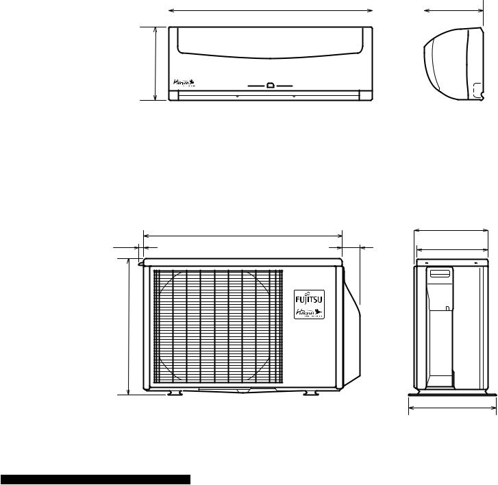
D I M E N S I O N S
Models : ASU9RLQ / AOU9RLQ |
(unit : mm) |
ASU12RLQ / AOU12RLQ |
|
INDOOR UNIT |
|
|
790 |
|
|
|
|
|
230 |
|||
|
|
|
|
|
||||||
|
|
|
|
|
|
|
|
|
|
|
|
|
|
|
|
|
|
|
|
|
|
|
|
|
|
|
|
|
|
|
|
|
|
|
|
|
|
|
|
|
|
|
|
|
|
|
|
|
|
|
|
|
|
|
|
|
|
|
|
|
|
|
|
|
|
|
|
|
|
|
|
|
|
|
|
|
|
|
|
|
|
|
|
|
|
|
|
|
|
|
|
|
|
|
|
|
|
|
|
|
|
|
|
|
|
|
|
|
|
|
|
|
|
|
|
|
|
|
|
|
283
OUTDOOR UNIT |
|
|
|
|
790 |
|
290 |
17 |
56 |
|
|
|
288 |
||
|
|
|
540
356
02-01

D I M E N S I O N S
Models : ASU18CL / AOU18CL |
(unit : mm) |
|
|
ASU18RL / AOU18RL |
|
790 |
215 |
275
|
508 |
48 |
20 |
347 |
320 |
540 |
125 |
790 |
66 |
300 |
578 |
|
|
10 |
|
|
02-02 |
|
|

R410A
WALL MOUNTED type
INVERTER
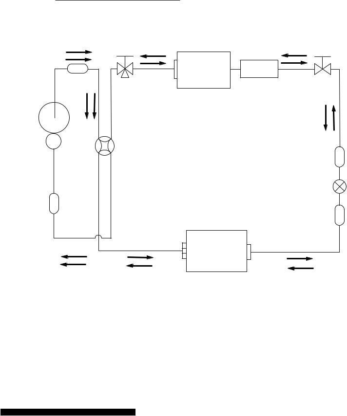
3 . REFRIGERANT SYSTEM DIAGRAM
REFRIGERANT SYSTEM DIAGRAM
Models : ASU9RLQ / AOU9RLQ
ASU12RLQ / AOU12RLQ
Muffler
Compressor
Heat exchanger 3-Way ( INDOOR ) valve
2-Way valve
 Muffler
4-Way valve
Strainer
|
Expansion valve |
Heat exchanger |
Strainer |
( OUTDOOR ) |
|
AOU9RLQ |
|
(2Pass) |
|
AOU12RLQ
(4Pass)
 Cooling
 Heating
03-01
REFRIGERANT SYSTEM DIAGRAM
Models : ASU18CL / AOU18CL
ASU18RL/ AOU18RL
3-Way valve
Muffler
Compressor |
4-Way valve |
|
Sub-accumulator
Heat exchanger ( INDOOR )
Sub-heat |
2-Way |
|
valve |
||
exchanger |
||
|
||
( INDOOR ) |
|
|
Strainer |
|
Expansion valve |
Heat exchanger |
Strainer |
( OUTDOOR ) |
|
 Cooling
 Heating
03-02

R410A
WALL MOUNTED type
INVERTER
4 . CIRCUIT DIAGRAM
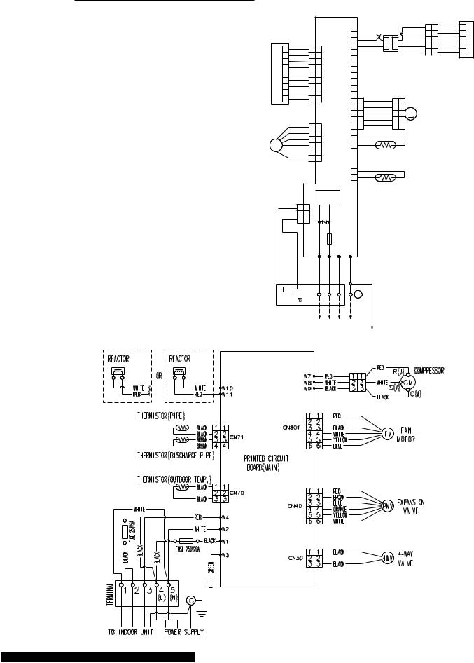
CIRCUIT DIAGRAM
Models : ASU9RLQ / AOU9RLQ
ASU12RLQ AOU12RLQ
INDOOR UNIT
OUTDOOR UNIT
|
|
|
|
CONTROL BOARD |
|
|
|
|
|
|
|
|
||||
|
|
|
|
|
|
|
|
|
|
|
|
WHITE |
1 1 |
WHITE |
1 |
|
|
|
|
|
|
|
|
1 |
WHITE |
|
|
|
2 2 |
YELLOW |
2 |
||
CN201 |
RED |
|
|
|
CN4 |
2 |
YELLOWRED |
4 |
3 |
RED |
3 3 |
RED |
3 |
|||
|
1 |
1 1 |
|
|
3 |
BLUE |
2 |
1 |
|
4 |
4 |
BLUE |
4 |
|||
|
WHITE |
|
|
4 |
|
|
|
5 5 |
5 |
|||||||
DISPLAYBOARD |
2 |
2 2 |
|
|
|
SWITCH |
|
|
||||||||
WHITE |
CN3 |
CN10 |
1 |
|
|
|
|
|
||||||||
8 |
WHITE |
8 |
8 |
|
|
|
|
|
|
|
|
|||||
|
3 |
WHITE |
3 |
3 |
|
|
|
|
|
|
|
|
|
|
||
|
4 |
4 |
4 |
|
|
2 |
|
|
|
|
|
|
|
|
||
|
5 |
WHITE |
5 |
5 |
|
|
3 |
|
|
|
|
|
|
|
|
|
|
6 |
WHITE |
6 |
6 |
|
|
4 |
|
|
|
|
|
|
|
|
|
|
7 |
WHITE |
7 |
7 |
|
|
5 |
|
|
|
|
|
|
|
|
|
|
9 |
WHITE |
9 |
9 |
|
|
1 |
1 |
RED |
|
1 1 |
|
|
|
|
|
|
|
|
|
|
|
CN2 |
2 |
2 |
ORANGE |
|
2 2 |
M |
|
|
|
|
|
|
|
|
|
|
3 3 |
YELLOW |
|
3 3 |
STEP MOTOR |
|
|||||
|
|
|
|
|
|
|
4 |
4 |
PINK |
|
4 4 |
|
|
|
|
|
|
|
BLUE |
1 1 |
|
|
5 |
5 |
BLUE |
|
5 5 |
|
|
|
|
|
|
|
|
YELLOW |
2 2 |
|
|
1 |
BLACK |
|
|
|
|
|
|
|
||
|
|
WHITE |
3 3 |
CN1 |
CN6 |
|
|
|
|
|
|
|
||||
F. M. |
|
BLACK |
4 |
4 |
2 |
BLACK |
|
|
|
|
|
|
|
|||
FAN MOTOR |
RED |
5 |
5 |
|
|
|
|
PIPE TEMPERATURE THERMISTOR |
|
|
|
6 |
6 |
|
|
|
|
|
|
|
|
|
|
|
|
|
CN5 |
1 |
BLACK |
|
|
|
|
|
SW |
|
2 |
BLACK |
|
|
|
|
|
|
|
|
|
ROOM TEMPERATURE THERMISTOR |
|
|
|
POWER CIRCUIT |
|
||||||
GRAY 3 3 |
CN7 |
|
BARISTOR |
|
|
|
|||
GRAY |
2 |
2 |
|
|
|
|
|||
1 1 |
|
|
|
|
|
|
|
||
|
|
|
|
|
|
FUSE |
|
|
|
|
|
|
|
|
|
3.15A |
|
|
|
|
|
|
|
W1 |
W2 |
W3 |
W4 |
|
|
|
|
|
|
WHITE |
BLACK |
RED |
GREEN |
|
YELLOW/ |
THERMAL FUSE 1 |
2 |
3 |
|
|
|||||
|
G |
||||||||
102 |
|
|
|
|
|
|
|
|
|
TERMINAL |
|
|
|
|
|
|
GREEN |
||
|
|
|
|
|
|
|
|
|
|
AIR CLEAN UNIT
04-01
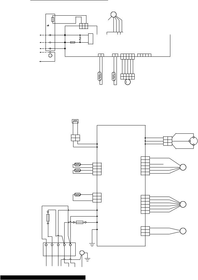
CIRCUIT DIAGRAM
Models : ASU18CL / AOU18CL
ASU18RL / AOU18RL
INDOOR UNIT
|
G 3 2 1 FUSETHERMAL 102 TERMINAL |
|
|
GRAY |
GRAY |
|
|
|
|
3 2 1 |
|
||
|
|
|
3 2 1 |
CIRCUIT POWER |
||
UNITOUTDOOR TO |
W1 |
|
CN7 |
|
||
|
|
|
||||
WHITE |
|
|
|
|||
W2 |
|
|
|
|||
BLACK |
|
VARISTOR |
|
|||
RED W3 |
FUSE |
|
||||
15A3. |
|
|||||
|
GREEN / |
|
|
|
|
|
|
YELLOW |
|
|
|
|
|
|
|
|
|
|
RTHERMISTO |
TEMPERATURE ROOM |
|
OUTDOOR UNIT |
|
|
|
||
MOTOR FAN |
|
|
|
|
|
|
|
|
INDICATOR PCB ASSY |
|||||||||||||||||
|
|
|
FM |
|
|
|
|
|
|
|
|
|
|
|
|
|
|
|
|
|
CN201 |
|||||
|
|
|
|
|
|
|
|
|
|
|
|
|
|
|
|
|
|
|
|
|||||||
|
|
|
|
|
|
|
|
|
|
|
|
|
|
|
|
|
|
|
|
|
|
|
|
|
||
|
|
|
|
|
|
|
|
|
|
7 |
6 |
5 |
4 |
3 |
2 |
1 |
|
|||||||||
|
RED |
BLUE YELLOW WHITE BLACK |
|
|
WHITE |
WHITE |
WHITE |
WHITE |
WHITE |
WHITE |
RED |
|||||||||||||||
|
|
|
|
|
|
|
|
|
|
|
|
|
|
|
|
|
|
|
|
|
|
|
|
|
|
|
|
6 |
5 |
4 |
1 2 3 |
|
|
7 |
6 |
5 |
4 |
|
3 |
2 |
1 |
|
|
||||||||||
SW |
6 |
5 |
4 |
3 |
2 |
1 |
|
|
7 |
6 |
5 |
4 |
|
3 |
2 |
1 |
|
|
||||||||
|
|
|
CN1 |
|
|
|
|
|
|
CN3 |
|
|||||||||||||||
|
|
|
|
|
|
|
|
|
|
|
||||||||||||||||
CONTROLLER PCB ASSY
CN5 |
CN6 |
1 2 |
1 2 |
BLACK BLACK |
BLACK BLACK |
|
TEMPERATURE PIPE THERMISTOR |
CN2 |
CN10 |
1 2 3 4 5 |
1 2 3 4 5 |
1 2 3 4 5 |
|
RED ORANGE YELLOW PINK BLUE |
|
1 2 3 4 5 |
|
1 2 3 4 5 |
|
M |
|
MOTOR STEP |
|
REACTOR
YELLOW |
YELLOW |
|
|
|
2 |
1 |
|
W7 |
RED |
2 |
1 |
|
WHITE |
|
|
W8 |
|||
|
WHITE |
W10 |
BLACK |
|
|
W9 |
|||
|
RED |
|
||
|
W11 |
|
||
|
|
|
|
PIPE TEMP. THERMISTOR |
|
|
|
|
1 |
1 |
RED |
|||
|
|
|
BLACK |
1 |
1 |
|
|
2 |
2 |
BLACK |
|
|
|
|
CN801 |
3 |
3 |
||||
|
|
|
BLACK |
2 |
2 |
CN71 |
4 |
4 |
WHITE |
|
|
|
|
BROWN |
3 |
3 |
|
5 |
5 |
YELLOW |
|
|
|
|
BROWN |
4 |
4 |
|
|
6 |
6 |
BLUE |
DISCHARGE PIPE TEMP. THERMISTOR |
|
|
|
|
|
|
|
|||
|
|
|
|
|
CONTROLLER PCB ASSY |
|
|
|
||
OUTDOOR TEMP. THERMISTOR |
|
|
|
|
|
|
|
|||
|
|
|
BLACK |
1 |
1 |
|
|
|
|
RED |
|
|
|
|
|
|
1 |
1 |
|||
|
|
|
BLACK |
2 |
2 |
CN70 |
|
|||
|
|
|
3 |
3 |
|
|
2 |
2 |
BROWN |
|
|
|
|
|
|
|
|
CN40 |
3 |
3 |
BLUE |
|
WHITE |
|
|
|
|
|
4 |
4 |
ORANGE |
|
|
|
|
|
|
|
|
||||
|
|
|
RED |
|
W4 |
|
5 |
5 |
YELLOW |
|
|
|
|
WHITE |
|
|
6 |
6 |
WHITE |
||
FUSE |
|
|
|
W2 |
|
|
|
|
||
|
|
|
|
|
|
|
|
|||
5A-250V |
|
|
BLACK |
W1 |
|
|
|
|
||
|
|
BLACK |
|
|
|
|
|
|
||
BLACK |
BLACK |
FUSE 20A-250V |
W3 |
CN30 |
1 |
1 |
BLACK |
|||
GREEN |
|
2 |
2 |
|
||||||
|
|
|
|
|
|
|||||
|
|
|
|
|
|
|
BLACK |
|||
|
|
|
|
|
|
|
|
3 |
3 |
|
|
|
RED |
|
|
|
1 |
1 |
|
R(R) |
||
WHITE |
|
C M COMPRESSOR |
|||
2 |
2 |
|
|||
S(S) |
|||||
3 |
3 |
C(T) |
|||
|
|
BLACK |
|
||
 F M FAN MOTOR
E V EXPANSION VALVE
4WV 4-WAY VALVE
TERMINAL 1 2 3 4 5
(L) (N) G
TO INDOOR UNIT POWER SUPPLY
04-02

R410A
WALL MOUNTED type
INVERTER
5 . DESCRIPTION OF EACH CONTROL OPERATION
1. COOLING OPERATION
1-1 COOLING CAPACITY CONTROL
A sensor (room temperature thermistor) built in the indoor unit body will usually perceive difference or variation between a set temperature and present room temperature, and controls the operation frequency of the compressor.
*If the room temperature is°F(2°C)4 higher than a set temperature, the compressor operation frequency will attain to maximum performance.
*If the room temperature is°F(25.5°C)lower than a set temperature, the compressor will be stopped.
*When the room temperature is between °F(+2°C)+4 to -5°F(-2.5°C)of the setting temperature, the compressor frequency is controlled within the range shown in Table1.
However, the maximum frequency is limited in the range shown in Figure 1 based on the fan speed mode and the outdoor temperature.
( Table 1 : Compressor Frequency Range )
|
minimum |
maximum |
maximum |
|
frequency |
frequency |
frequency |
ASU9RLQ |
18Hz |
61Hz |
80Hz |
ASU12RLQ |
18Hz |
80Hz |
96Hz |
ASU18CL |
18Hz |
70Hz |
90Hz |
ASU18RL |
18Hz |
70Hz |
90Hz |
( Fig. 1 : Limit of Maximum Frequency based on Outdoor Temperature )
Outside air |
Outside air |
|
|
Hi |
Me |
Lo |
Quiet |
|
temperature |
temperature |
9RLQ |
A zone |
80Hz |
61Hz |
51Hz |
33Hz |
|
|
|
97°F(36°C) |
|
B zone |
80Hz |
61Hz |
51Hz |
33Hz |
|
|
|
||||||
|
|
|
C zone |
80Hz |
61Hz |
51Hz |
33Hz |
|
|
|
|
|
|||||
93°F(34°C) |
A zone |
|
|
D zone |
51Hz |
42Hz |
36Hz |
27Hz |
|
90°F(32°C) |
|
E zone |
51Hz |
42Hz |
36Hz |
27Hz |
|
|
|
|
||||||
|
|
|
F zone |
51Hz |
42Hz |
36Hz |
27Hz |
|
|
B zone |
|
|
|||||
86°F(30°C) |
|
12RLQ |
A zone |
96Hz |
61Hz |
51Hz |
33Hz |
|
|
70°F(21°C) |
|
B zone |
96Hz |
61Hz |
51Hz |
33Hz |
|
|
|
|
||||||
|
C zone |
|
|
C zone |
96Hz |
61Hz |
51Hz |
33Hz |
66°F(19°C) |
|
|
D zone |
57Hz |
42Hz |
36Hz |
27Hz |
|
|
54°F(12°C) |
|
||||||
|
|
|
E zone |
57Hz |
42Hz |
36Hz |
27Hz |
|
50°F(10°C) |
D zone |
|
|
F zone |
57Hz |
42Hz |
36Hz |
27Hz |
|
18CL |
A zone |
90Hz |
45Hz |
42Hz |
30Hz |
||
|
36°F(2°C) |
|||||||
|
|
|
B zone |
90Hz |
45Hz |
42Hz |
30Hz |
|
32°F(0°C) |
E zone |
|
|
C zone |
90Hz |
45Hz |
42Hz |
30Hz |
|
|
|
D zone |
58Hz |
38Hz |
34Hz |
24Hz |
|
|
|
|
|
|||||
|
F zone |
|
|
E zone |
58Hz |
38Hz |
34Hz |
24Hz |
|
|
|
F zone |
58Hz |
38Hz |
34Hz |
24Hz |
|
|
|
|
18RL |
A zone |
90Hz |
45Hz |
42Hz |
30Hz |
|
|
|
|
B zone |
90Hz |
45Hz |
42Hz |
30Hz |
|
|
|
|
C zone |
90Hz |
45Hz |
42Hz |
30Hz |
|
|
|
|
D zone |
58Hz |
38Hz |
34Hz |
24Hz |
|
|
|
|
E zone |
58Hz |
38Hz |
34Hz |
24Hz |
|
|
|
|
F zone |
58Hz |
38Hz |
34Hz |
24Hz |
When the compressor operates for 30 minutes continuously at over the maximum frequency , the maximum frequency is changed from Maximum Frequency
 to Maximum Frequency
 . The room temperature is controlled°F(1°C)2 lower than the setting temperature for 40 minutes after starting the operation.
After 40 minutes, it is controlled based on the normal setting temperature.
05-01
2. HEATING OPERATION
2-1 HEATING CAPACITY CONTROL
A sensor (room temperature thermistor) built in the indoor unit body will usually perceive difference or variation between a set temperature and present room temperature, and controls the operation frequency of the compressor.
*If the room temperature is lower by°F(3°C)6 than a set temperature, the compressor operation frequency will attain to maximum performance.
*If the room temperature is higher°F(25 .5°C)than a set temperatire, the compressor will be stopped.
*When the room temperature is between °F(+2°C)+4 to -6°F(-3°C)of the setting temperature, the compressor frequency is controlled within the range shown in Table2.
However, the maximum frequency is limited in the range shown in Figure 2 based on the fan speed mode and the outdoor temperature.
( Table 2 : Compressor Frequency Range )
|
minimum |
maximum |
|
frequency |
frequency |
ASU9RLQ |
18Hz |
130Hz |
ASU12RLQ |
18Hz |
130Hz |
ASU18CL |
- |
- |
ASU18RL |
18Hz |
119Hz |
( Fig.2 : Limit of Maximum Frequency based on Outdoor Temperature )
Outside air |
|
|
|
Outside air |
|
|
Hi |
Me |
Lo |
Quiet |
||||
temperature |
|
|
temperature |
|
|
|||||||||
|
|
9RLQ |
A zone |
130Hz |
96Hz |
80Hz |
68Hz |
|||||||
|
|
|
|
|
|
|
|
|
||||||
66°F(19°C) |
|
|
|
|
|
|
|
B zone |
130Hz |
96Hz |
80Hz |
54Hz |
||
|
|
|
|
|
|
|
|
|||||||
|
|
|
|
|
|
|
|
|||||||
|
|
|
|
|
C zone |
|
|
|
|
C zone |
130Hz |
96Hz |
80Hz |
45Hz |
|
|
|
|
|
|
|
|
63°F(17°C) |
12RLQ |
A zone |
130Hz |
96Hz |
80Hz |
68Hz |
|
|
|
|
|
|
|
|
|||||||
57°F(14°C) |
|
|
|
|
|
|
|
|
B zone |
130Hz |
96Hz |
80Hz |
54Hz |
|
|
|
|
|
|
|
|
|
|||||||
|
|
|
|
|
B zone |
|
|
|
|
C zone |
130Hz |
96Hz |
80Hz |
45Hz |
|
|
|
|
|
|
|
|
54°F(12°C) |
18CL |
A zone |
- |
- |
- |
- |
|
|
|
|
|
|
|
|
|||||||
|
|
|
|
|
|
|
|
|
|
B zone |
- |
- |
- |
- |
|
|
|
|
|
A zone |
|
|
|
|
C zone |
- |
- |
- |
- |
|
|
|
|
|
|
|||||||||
|
|
|
|
|
|
|
|
|
18RL |
A zone |
119Hz |
90Hz |
70Hz |
58Hz |
|
|
|
|
|
|
|
|
|
|
B zone |
119Hz |
90Hz |
70Hz |
58Hz |
|
|
|
|
|
|
|
|
|
|
C zone |
119Hz |
90Hz |
70Hz |
58Hz |
* The room temperature is controlled°F(2°C)4 higher than the setting temperature for 60 minutes after starting the operation.
After 60 minutes, it is controlled based on the normal setting temperature.
05-02
3. DRY OPERATION
3-1 INDOOR UNIT CONTROL
The compressor rotation frequency shall change according to the temperature, set temperature, and room temperature variation which the room temperature sensor of the indoor unit body has detected as shown in the Table 3. However, after the compressor is driven, the indoor unit shall run at operation frequency of 58Hz, for a minute.
( Table 3 : Compressor frequency )
|
Operating |
|
frequency |
ASU9RLQ |
33Hz |
ASU12RLQ |
33Hz |
ASU18CL |
24Hz |
ASU18RL |
24Hz |
( Fig.3 : Compressor Control based on Room Temperature )
room |
room |
||||||
temperature |
temperature |
||||||
Ts+1°F(0.5°C) |
|
compressor ON |
|
|
Ts+3°F(1.5°C) |
||
|
|
|
|||||
|
|
|
|
|
|
||
|
|
|
|
|
|
||
|
|
|
|
|
|
|
|
|
compressor OFF |
|
|
|
|||
|
|
|
|
|
|||
|
|
|
|
|
|||
( Fig.4 : Indoor Fan Control )
Compressor
ON
OFF
Indoor fan
Dry air flow
 S-Lo
S-Lo
OFF |
|
|
|
|
|
|
|
|
|
10 |
30 |
60 |
180 |
60 |
180 |
60 |
10 |
30 |
(SEC) |
|
|
|
|
|
|
|
|
|
When an IAQ works in 9/12LA models, it operate with S-LO without stopping.
05-03
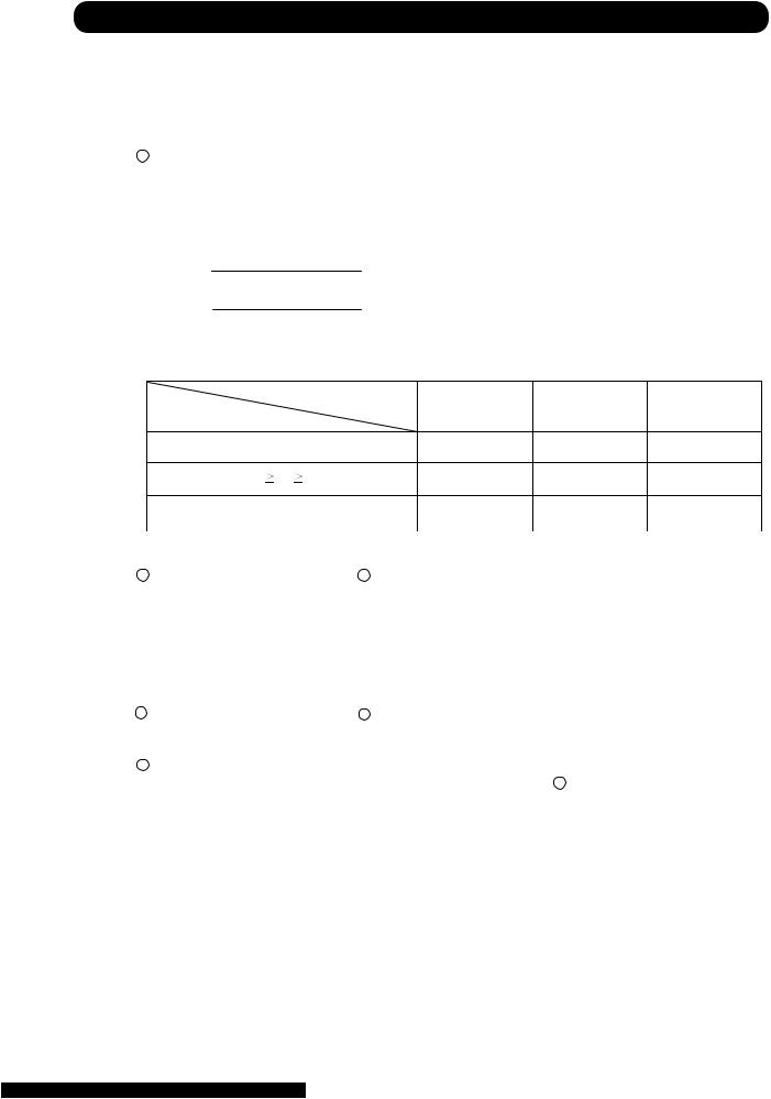
4. AUTO CHANGEOVER OPERATION
When the air conditioner is set to the AUTO mode by remote cintrol, operation starts in the optimum mode from amoung the HEATING, COOLING, DRY and MONITORING modes. During operation, the optimum mode is automatically swiched in accordance with temperature changes. The temperature can be set between 64°F(18°C)and 88°F(30°C)in 2°F(1°C)steps.
1 .When operation starts, only the indoor and outdoor fans are operated for 1 minute. After 1 minute, the room temperature and outside air temperature are sensed and the operation mode is selected in accordance with the table below.
( Fig.5 : Outside air temperature zone selection )
C zone
90°F(32°C)
B zone
14°F(-10°C)
A zone
( Table.4 Operation mode selection table)
Outside air temperature |
(TO) |
B zone |
C zone |
|
Room temperature(TB) |
A zone |
|||
|
|
|
||
TB > TS+4°F(2°C) |
Monitoring |
Cooling |
Cooling |
|
(automatic dry) |
(automatic dry) |
|||
|
|
|||
TS+4°F(2°C) TB TS - 4°F(2°C) |
Monitoring |
Monitoring |
Monitoring |
|
TB<TS- 4°F(2°C) |
*Heating |
*Heating |
Monitoring |
|
|
|
*18CL is Monitoring |
||
2 .When COOING was selected at 1 , the air conditioner operates as follow:
 The same operation as COOLING OPERATION of item 1 above is performed.
 When the room temperature has remained at (set tempareure -2°F(1°C)) for 8 minutes, operation is automatically switched to DRY and the same operation as DRY OPERATION of item 3 above
is performed.
 If the room temperature reaches (set temperature+4°F(2°C) during DRY operation, operation returns to COOLING operation.
3.When HEATING was selected at 1 , the same operation as HEATING OPERATION of item 2 above is performed.
4 When the compressor was stopped for 6 consecutive minutes by the temperature control function after the COOLING or HEATING operation mode was selected at 1 above, operation is switched to MONITORING and the operation mode is selected again.
05-04
5. INDOOR FAN CONTROL
(1).Fan speed
( Table 5 : Indoor Fan Speed )
|
ASU9RLQ |
|
Operat ion mode |
Air flow mode |
Speed (rpm) |
Heating |
Hi |
1390 |
|
Me+ |
1350 |
|
Me |
1200 |
|
Lo |
1000 |
|
Quiet |
760 |
|
Cool air |
760 |
|
prevention |
|
|
|
|
|
S-Lo |
480 |
Cooling |
Hi |
1300 |
Fan |
Me |
1120 |
|
Lo |
950 |
|
Quiet |
700 |
Dry |
|
700 |
|
ASU18CL |
|
Operation mode |
Air flow mode |
Speed (rpm) |
Heating |
Hi |
- |
|
Me+ |
- |
|
Me |
- |
|
Lo |
- |
|
Quiet |
- |
|
Cool air |
- |
|
prevention |
|
|
|
|
|
S-Lo |
480 |
Cooling |
Hi |
1480 |
Fan |
Me |
1260 |
|
Lo |
1040 |
|
Quiet |
850 |
Dry |
|
850 |
|
ASU12RLQ |
|
Operation mode |
Air flow mode |
Speed (rpm) |
Heating |
Hi |
1440 |
|
Me+ |
1350 |
|
Me |
1200 |
|
Lo |
1000 |
|
Quiet |
760 |
|
Cool air |
760 |
|
prevention |
|
|
|
|
|
S-Lo |
480 |
Cooling |
Hi |
1370 |
Fan |
Me |
1150 |
|
Lo |
950 |
|
Quiet |
700 |
Dry |
|
700 |
|
ASU18RL |
|
Operation mode |
Air flow mode |
Speed (rpm) |
Heating |
Hi |
1480 |
|
Me+ |
1420 |
|
Me |
1300 |
|
Lo |
1110 |
|
Quiet |
950 |
|
Cool air |
850 |
|
prevention |
|
|
|
|
|
S-Lo |
480 |
Cooling |
Hi |
1480 |
Fan |
Me |
1260 |
|
Lo |
1040 |
|
Quiet |
850 |
Dry |
|
850 |
(2).FAN OPERATION
The airflow can be switched in 5 steps such as AUTO, QUIET, LOW, MED, HIGH, while the indoor fan only runs.
When Fan mode is set at (Auto), it operates on (MED) Fan Speed.
05-05
(3).COOLING OPERATION
Switch the airflow [AUTO], and the indoor fan motor will run according to a room temperature, as shown in Figure 6.
On the other hand, if switched in [HIGH]  [QUIET], the indoor motor will run at a constant airflow of [COOL] operation modes QUIET, LOW, MED, HIGH, as shown in Table 5.
+4°F(+2°C)
+2°F(+1°C)
(4).DRY OPERATION
Refer to the table 4.
Durring the dry mode operation, the fan speed setting can not be changed.
(Fig.6)
airflow change - over ( Cooling:AUTO )
When the room temperature rises
HIGH mode |
+5°F(+2.5°C) |
|
MED mode
+3°F(+1.5°C)
LOW mode
When the room temperature lowers
(Room temperature) D (Setting temperature)
(5).HEATING OPERATION
Switch the airflow [AUTO], and the |
|
|
|
(Fig.7) |
|||||||||||||
indoor fan motor will run according |
|
|
|
|
|
airflow change - over ( Heating:AUTO) |
|||||||||||
to a room temperature, as shown in |
|
|
|
When the room |
|||||||||||||
Figure 7. |
|
|
|
|
|
temperature rises |
|||||||||||
On the other hand, if switched |
|
|
|
|
|
|
LOW mode |
|
|
|
|
||||||
|
|
|
|
|
|
|
|||||||||||
[HIGH] [QUIET], the indoor motor |
-2°F |
(-1°C) |
|
|
|
|
|
|
|
|
|
-3°F(-1.5°C) |
|||||
|
|
|
|||||||||||||||
will run at a constant airflow of [HEAT] |
|
|
|
|
|
|
|
|
|
|
|
|
|
|
|||
|
|
|
|
|
|
|
|
|
|
|
|
|
|
||||
operation modes QUIET, LOW, MED, |
|
|
|
|
|
|
MED mode |
|
|
|
|
||||||
HIGH, as shown in Table 5. |
-4°F(-2°C) |
|
|
|
|
|
|
|
|
|
|||||||
|
|
||||||||||||||||
|
|
|
|
|
|
|
|
|
|
|
|
|
|
|
-5°F(-2.5°C) |
||
|
|
|
|
|
|
|
MED + mode |
|
|
|
|||||||
|
|
|
|
|
|
|
|
|
|
|
|||||||
|
|
|
|
|
|
|
|
|
When the room |
|
|||||||
|
|
|
|
|
|
|
|
|
temperature lowers |
|
|||||||
|
|
|
|
|
|
(Room temperature) D (Setting temperature) |
|
|
|||||||||
|
|
|
|
|
|
|
|
||||||||||
(6).COOL AIR PREVENTION CONTROL (Heating mode)
The maximum value of the indoor fan speed is set as shown in Figure 8, based on the detected temperature by the indoor heat exchanger sensor on heating mode.
(Fig.8 : Cool Air Prevention Control)
Indoor heat exchanger |
|
|
|
Indoor heatxchanger |
||||
temperature |
|
|
|
temperature |
||||
117°F(47°C) |
|
Hi |
|
|
|
|||
104°F(40°C) |
|
|
|
Me+ |
|
|
104°F(40°C) |
|
|
|
|
|
|||||
|
|
|
|
|
|
|
||
99°F(37°C) |
|
Lo |
|
|
|
93°F(34°C) |
||
|
|
|
|
|
|
|
||
|
|
|
|
|
|
|||
86°F(30°C) |
|
Cool air prevention |
|
|
90°F(32°C) |
|||
|
|
|
|
|
|
82°F(28°C) |
||
|
|
|
|
|
|
|||
|
|
|
|
|
|
|
|
|
|
|
|
|
|
|
|
|
|
S-Lo
05-06
6. OUTDOOR FAN CONTROL
(1). Fan Speed
( Table 6 : Outdoor fan speed ) |
|
|
(rpm) |
|||
|
|
ZONE |
|
Cooling |
Dry |
Heating |
ASU9RLQ |
|
A-D |
|
800/760/470 |
500 |
|
|
|
E |
|
400/280 |
400/280 |
760/680/470 |
|
|
F |
|
200 |
200 |
|
ASU12RLQ |
|
A-D |
|
800/760/470 |
500 |
|
|
|
E |
|
400/280 |
400/280 |
760/680/470 |
|
|
F |
|
250/200 |
250/200 |
|
ASU18CL |
|
A-D |
|
860/820/670/500 |
500 |
|
|
|
E |
|
400/340/280 |
400/340/280 |
- |
|
|
F |
|
280/250/230 |
280/250/230 |
|
|
|
|
|
|
|
|
ASU18RL |
|
A-D |
|
860/820/670/500 |
500 |
|
|
|
E |
|
400/340/280 |
400/340/280 |
820/750/670/450 |
|
|
F |
|
280/250/230 |
280/250/230 |
|
Refer to Fig1. |
|
|
|
|
|
|
(1). Fan Speed
*It runs at 500(A-D ZONE)/200(E,F ZONE) rpm for 20 seconds after starting up the outdoor fan.
*The outdoor fan speed mentioned avobe depends on the compressor frequency.
(When the compressor frequency increases, the outdoor fan speed also changes to the higher speed. When the compressor frequescy decreases, the outdoor fan speed also changes to the lower speed.)
*Outdoor temperature falls, and if it becomes E and F zone(Refer to Fig1), rotations of fan speed will fall.
*After the defrost control is operated on the heating mode, the fan speed keeps at the higher speed as table 7 without relating to the compressor frequency.
( Table 7 : Outdoor fan speed after the defrost )
|
Min |
ASU9RLQ |
800rpm |
ASU12RLQ |
900rpm |
ASU18CL |
- |
ASU18RL |
950rpm |
05-07
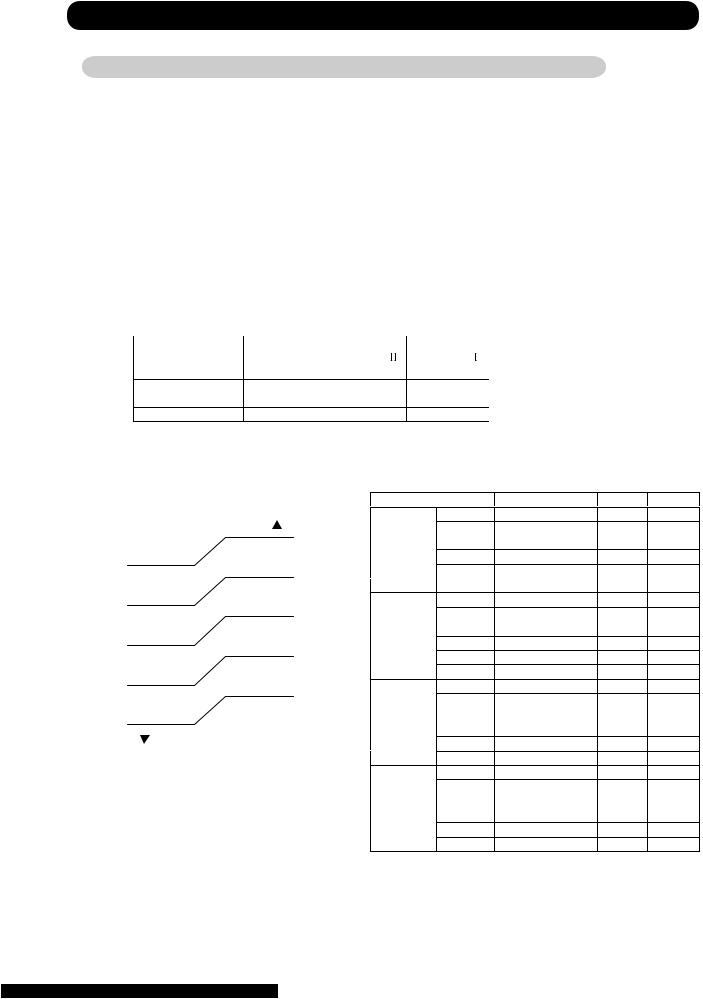
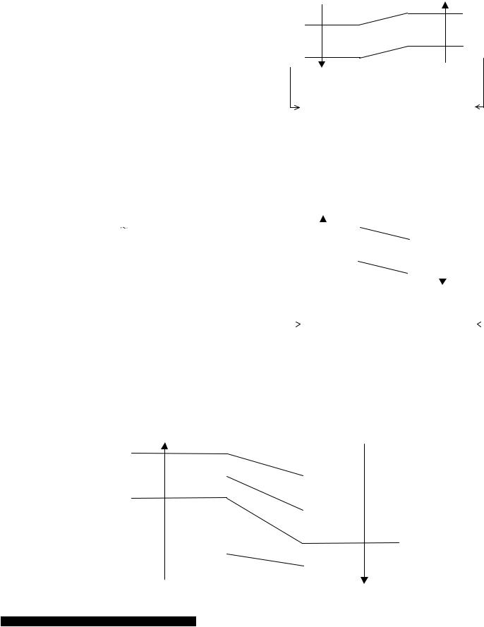
7. LOUVER CONTROL
(1). VERTICAL LOUVER CONTROL
(Function Range)
Each time the button is pressed, the air direction range will change as follow:
(Fig 9: Air Direction Range)
(Operation Range)
Cooling / Dry mode 


 Heating mode


 Fan mode
Use the air direction adjustments within the ranges shown above.
 The vertical airflow direction is set automatically as shown, in accordance with the type of operation selected.
Cooling / Dry mode |
Horizontal flow |
Heating mode |
Downward flow |
 When the temperature of the air being blown out is low at the start of heating operation or during defrosting, the airflow direction temporarily becomes
  to prevent cold air being blown onto the body.
 During use of the Cooling and Dry modes, do not set the Air Flow Direction Louver in the Heating range (
 ) for long period of time, since water vapor many condense near the outlet louvers and drop of water may drip from the air conditioner. During the Cooling and Dry modes, if the Air Flow Direction Louvers are left in the hating range for more than 30minutes, they will automatically
return to position .
.
 During Monitor operation in AUTO CHANGEOVER mode, the airflow direction automatically becomes
  , and it cannot be adjusted.
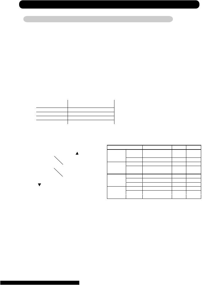
(2). SWING OPERATION
When the swing signal is received from the remote controller, the vertical louver starts to swing.
(Swinging Range)
Cooling mode / Dry mode / Fan mode(
 ) Heating mode / Fan mode(
 )
)
 When the indoor fan is either at S-lo or Stop mode, the swinging operation is interrrupted and the louver stops at the memorized position.
05-08
8. COMPRESSOR CONTROL
(1). OPEARTION FREQUENCY RANGE
The operation frequency of the compressor is different based on the operation mode as shown in the table 8.
(Table 8 : Compressor Operation Frequency Range)
|
Cooling |
|
Heating |
Dry |
|
|
Min |
Max |
Min |
Max |
|
|
|
||||
ASU9RLQ |
18Hz |
80Hz |
18Hz |
130Hz |
33Hz |
ASU12RLQ |
18Hz |
96Hz |
18Hz |
130Hz |
33Hz |
ASU18CL |
18Hz |
90Hz |
- |
- |
24Hz |
ASU18RL |
18Hz |
90Hz |
18Hz |
119Hz |
24Hz |
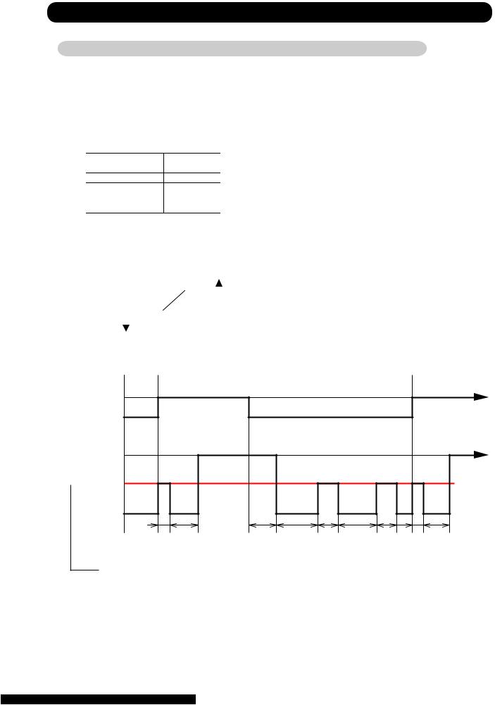
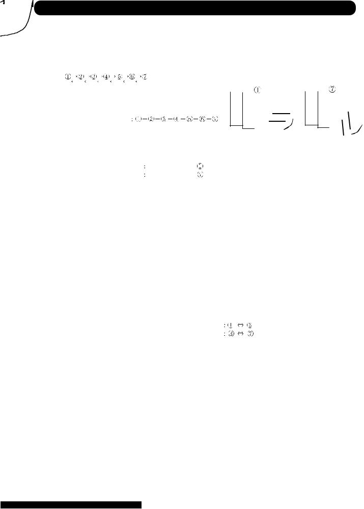
(2). OPEARTION FREQUENCY CONTROL AT START UP
The compressor frequency soon after the start-up is controlled as shown in the figure 10. (Fig.10 : Compressor Control at Start-up)
Frequency

Frequency

Frequency

Frequency

Frequency

Frequency 

Time |
Time |
Time |
Time |
Time |
Time |
|
(Frequency) |
|
|
|
|
|
|
|
Frequency |
Frequency |
Frequency |
Frequency |
Frequency |
Frequency |
ASU9RLQ |
56Hz |
74Hz |
87Hz |
97Hz |
108Hz |
119Hz |
ASU12RLQ |
56Hz |
74Hz |
87Hz |
97Hz |
108Hz |
119Hz |
ASU18CL |
40Hz |
59Hz |
72Hz |
80Hz |
101Hz |
110Hz |
ASU18RL |
40Hz |
59Hz |
72Hz |
80Hz |
101Hz |
110Hz |
(Time) |
|
|
|
|
|
|
|
Time |
Time |
Time |
Time |
Time |
Time |
ASU9RLQ |
80sec |
60sec |
60sec |
180sec |
60sec |
60sec |
ASU12RLQ |
80sec |
60sec |
60sec |
180sec |
60sec |
60sec |
ASU18CL |
60sec |
40sec |
40sec |
60sec |
150sec |
60sec |
ASU18RL |
60sec |
40sec |
40sec |
60sec |
150sec |
60sec |
05-09
 Loading...