


Fujitsu AOU24RLX, AOU42RLX, AUU42RCLX, AUU24RCLX, AOU18RLX User Manual
...SPLIT TYPE
ROOM AIR CONDITIONER
CASSETTE type
INVERTER
SERVICE
INSTRUCTION
Models Indoor unit Outdoor unit
AUU18RCLX AOU18RLX
AUU24RCLX AOU24RLX
AUU36RCLX AOU36RLX
AUU42RCLX AOU42RLX
R410A

CONTENTS
1. DESCRIPTION OF EACH CONTROL OPERATION
1. COOLING OPERATION.............................................................................................. |
01-01 |
2. HEATING OPERATION.............................................................................................. |
01-02 |
3. DRY OPERATION...................................................................................................... |
01-03 |
4. AUTO CHANGEOVER OPERATION......................................................................... |
01-04 |
5. INDOOR FAN CONTROL........................................................................................... |
01-05 |
6. OUTDOOR FAN CONTROL....................................................................................... |
01-07 |
7. LOUVER CONTROL................................................................................................... |
01-08 |
8. COMPRESSOR CONTROL........................................................................................ |
01-09 |
9. TIMER OPERATION CONTROL................................................................................ |
01-10 |
10. ELECTRONIC EXPANSION VALVE CONTROL........................................................ |
01-12 |
11. TEST OPERATION CONTROL.................................................................................. |
01-12 |
12. PREVENT TO RESTART FOR 3 MINUTES ( 3 MINUTES ST )................................ |
01-12 |
13. 4-WAY VALVE EXTENSION SELECT....................................................................... |
01-12 |
14. AUTO RESTART........................................................................................................ |
01-12 |
15. PUMP DOWN ( Refrigerant collecting operation )...................................................... |
01-13 |
16. COMPRESSOR PREHEATING.................................................................................. |
01-13 |
17. DEFROST OPERATION CONTROL.......................................................................... |
01-13 |
18. DRAIN PUMP OPERATION....................................................................................... |
01-15 |
19. ENERGY SAVE FUNCTION....................................................................................... |
01-15 |
20. VARIOUS PROTECTIONS......................................................................................... |
01-16 |
2. TROUBLE SHOOTING
2-1 |
ERROR DISPLAY...................................................................................................... |
02-01 |
|
2-1-1 |
WIRED REMOTE CONTROLLER DISPLAY...................................................... |
02-01 |
|
2-1-2 |
OUTDOOR UNIT DISPLAY................................................................................ |
02-03 |
|
2-2 |
TROUBLE SHOOTING WITH ERROR CODE.......................................................... |
02-04 |
|
2-3 |
TROUBLE SHOOTING WITH NO ERROR CODE.................................................... |
02-24 |
|
2-4 |
SERVICE PARTS INFORMATION............................................................................ |
02-29 |
|

3. REPLACEMENT PARTS
1 REPLACEMENT PARTS ( For OUTDOOR UNIT )....................................................... |
03-01 |
|
1-1 For AOU18/ 24/ 36RLX........................................................................................... |
03-01 |
|
1-1-1 PARTS LAYOUT DRAWING............................................................................... |
03-01 |
|
1-1-2 WIRING................................................................................................................ |
03-03 |
|
1-1-3 DISASSEMBLY PROCESS................................................................................. |
03-04 |
|
1-1-4 ASSEMBLY PROCESS of INVERTER UNIT...................................................... |
03-09 |
|
1-2 For AOU42RLX....................................................................................................... |
03-15 |
|
1-2-1 |
PARTS LAYOUT DRAWING............................................................................... |
03-15 |
1-2-2 |
WIRING................................................................................................................ |
03-17 |
1-2-3 |
DISASSEMBLY PROCESS................................................................................. |
03-19 |
1-2-4 |
ASSEMBLY PROCESS of INVERTER UNIT...................................................... |
03-25 |
2 REPLACEMENT PARTS ( For INDOOR UNIT )........................................................... |
03-30 |
|
2-1 PARTS LAYOUT DRAWING................................................................................... |
03-30 |
|

R410A
CASSETTE type
INVERTER
1 . DESCRIPTION OF EACH CONTROL OPERATION

1. COOLING OPERATION
1-1 COOLING CAPACITY CONTROL
A sensor (room temperature thermistor) built in the indoor unit will usually perceive difference or variation between a set temperature and present room temperature, and controls the operation frequency of the compressor.
*If the room temperature is 3.6 degF(2 degC) higher than a set temperature, the compressor operation frequency will attain to maximum performance.
*If the room temperature is 3.6 degF(2 degC) lower than a set temperature, the compressor will be stopped.
*When the room temperature is between +3.6 degF(+2 degC) to -3.6 degF(-2 degC) of
the setting temperature, the compressor frequency is controlled within the range shown in Table1. However, the maximum frequency is limited in the range shown in Figure 1 based on the
fan speed mode and the outdoor temperature.
( Table 1 : Compressor Frequency Range )
|
minimum |
maximum |
|
frequency |
frequency |
AUU18RCLX |
20Hz |
63Hz |
AUU24RCLX |
20Hz |
80Hz |
AUU36RCLX |
20Hz |
90Hz |
AUU42RCLX |
25Hz |
92Hz |
( Fig. 1 : Limit of Maximum Frequency based on Outdoor Temperature )
Outdoor air |
|
|
Fan speed mode |
Hi |
Me |
Lo |
|||
|
|
|
|
||||||
temperature |
|
|
|
|
|
|
|
||
A zone |
|
AUU18RCLX |
A zone |
63Hz |
45Hz |
45Hz |
|||
|
|
|
|
||||||
87.8°F |
|
|
|
|
B zone |
45Hz |
35Hz |
35Hz |
|
|
|
|
|
|
|||||
|
|
|
|
|
C zone |
35Hz |
35Hz |
35Hz |
|
(31°C) |
B zone |
|
|
||||||
|
|
D zone |
35Hz |
30Hz |
30Hz |
||||
|
|
|
|
|
|||||
66.2°F |
|
|
AUU24RCLX |
A zone |
80Hz |
55Hz |
55Hz |
||
|
|
|
B zone |
55Hz |
45Hz |
45Hz |
|||
(19°C) |
C zone |
|
|
||||||
|
|
C zone |
45Hz |
45Hz |
45Hz |
||||
|
|
|
|
|
|||||
51.8°F |
|
|
|
|
D zone |
45Hz |
35Hz |
35Hz |
|
|
D zone |
|
AUU36RCLX |
A zone |
90Hz |
75Hz |
75Hz |
||
(11°C) |
|
||||||||
|
|
B zone |
75Hz |
70Hz |
70Hz |
||||
|
|
|
|
|
|
||||
|
|
|
|
|
|
C zone |
70Hz |
63Hz |
63Hz |
|
|
|
|
|
|
D zone |
63Hz |
55Hz |
55Hz |
|
|
|
|
|
AUU42RCLX |
A zone |
92Hz |
72Hz |
72Hz |
|
|
|
|
|
|
B zone |
72Hz |
60Hz |
60Hz |
|
|
|
|
|
|
C zone |
60Hz |
60Hz |
60Hz |
|
|
|
|
|
|
D zone |
60Hz |
53Hz |
53Hz |
01-01

2. HEATING OPERATION
2-1 HEATING CAPACITY CONTROL
A sensor (room temperature thermistor) built in the indoor unit will usually perceive difference or variation between a set temperature and present room temperature, and controls the operation frequency of the compressor.
*If the room temperature is lower 5.4 degF(3 degC) than a set temperature, the compressor operation frequency will attain to maximum performance.
*If the room temperature is higher 3.6 degF(2 degC) than a set temperature, the compressor will be stopped.
*When the room temperature is between +3.6 degF(+2 degC) to -5.4 degF(-3 degC) of
the setting temperature, the compressor frequency is controlled within the range shown in Table2. However, the maximum frequency is limited in the range shown in Figure 2 based on
the outdoor temperature.
( Table 2 : Compressor Frequency Range )
|
minimum |
maximum |
|
frequency |
frequency |
AUU18RCLX |
20Hz |
87Hz |
AUU24RCLX |
20Hz |
87Hz |
AUU36RCLX |
20Hz |
95Hz |
AUU42RCLX |
23Hz |
92Hz |
( Fig.2 : Limit of Maximum Frequency based on Outdoor Temperature )
Outdoor air |
|
|
|
|
Limit of Maximum |
||
|
|
|
|
Frequency |
|||
temperature |
|
|
|
|
|||
E zone |
|
AUU18RCLX |
A zone |
87Hz |
|||
|
|
|
|
||||
68°F |
|
|
|
B zone |
85Hz |
||
|
|
|
|
||||
|
|
|
|
C zone |
70Hz |
||
(20°C) |
D zone |
|
|
||||
|
|
D zone |
70Hz |
||||
|
|
|
|
|
|||
60.8°F |
|
|
|
E zone |
60Hz |
||
|
|
AUU24RCLX |
A zone |
87Hz |
|||
(16°C) |
C zone |
|
|||||
|
|
B zone |
85Hz |
||||
|
|
|
|
|
|||
53.6°F |
|
|
|
|
|
C zone |
70Hz |
|
|
|
|
|
D zone |
70Hz |
|
|
|
|
|
||||
(12°C) |
|
|
|
||||
B zone |
|
|
E zone |
60Hz |
|||
|
|
|
|
|
|||
41°F |
|
|
|
|
AUU36RCLX |
A zone |
95Hz |
|
|
|
|
|
B zone |
95Hz |
|
|
A zone |
|
|
||||
(5°C) |
|
|
|||||
|
|
C zone |
90Hz |
||||
|
|
|
|
|
|
||
|
|
|
|
|
|
D zone |
80Hz |
|
|
|
|
|
|
E zone |
80Hz |
|
|
|
|
|
AUU42RCLX |
A zone |
92Hz |
|
|
|
|
|
|
B zone |
92Hz |
|
|
|
|
|
|
C zone |
90Hz |
|
|
|
|
|
|
D zone |
80Hz |
|
|
|
|
|
|
E zone |
80Hz |
01-02
3. DRY OPERATION
3-1 INDOOR UNIT CONTROL
The compressor rotation frequency shall change according to set temperature and room temperature variation which the room temperature sensor of the indoor unit has detected as shown in the Table 3.
( Table 3 : Compressor frequency )
|
Operating frequency |
|
|
AUU18RCLX |
25Hz |
AUU24RCLX |
30Hz |
AUU36RCLX |
45Hz |
AUU42RCLX |
30Hz |
( Fig.3 : Compressor Control based on Room Temperature )
Room |
|
Room |
|
temperature |
temperature |
||
|
Compressor ON |
|
Ts+2.7 degF |
|
|
|
|
Ts+1.8 degF |
|
|
(1.5 degC) |
|
|
|
|
(1 degC) |
Compressor OFF |
|
|
|
|
|
Ts : Setting temperature |
( Fig.4 : Indoor Fan Control )
Compressor
ON
OFF
Indoor fan
air flow mode
ON
OFF
30 |
5 |
30 |
120 |
5 |
(sec) |
|
|
|
180 |
180 |
|
Air flow mode : Lo
01-03
4. AUTO CHANGEOVER OPERATION
When the air conditioner is set to the AUTO mode by remote control, operation starts in the optimum mode from among the HEATING, COOLING and MONITORING modes. During operation, the optimum mode is automatically swiched in accordance with temperature changes. The temperature can be set between 64°F(18°C) and 88°F(30°C) in 2 degF(1 degC) steps.
1When operation starts, only the indoor fan is operated for 1 minute. (Air flow mode: S- Lo) After 1 minute, depends on the room temperature and outdoor unit's operarion mode, the operation mode is selected in accordance with the table below.
( Table 4 : Operation mode selection table )
Room temperature :TR |
Operation mode |
|||
|
|
|
||
TR > Ts +3.6 degF |
|
Cooling |
||
= |
(2 degC) |
|
||
|
|
|
||
Ts +3.6 degF > TR > Ts-3.6 degF |
Monitoring |
|||
(2 degC) |
|
(2 degC) |
||
|
|
|||
Ts +3.6 degF > TR |
|
Heating |
||
(2 degC) |
= |
|
||
|
|
|
||
|
|
|
||
Ts : Setting temperature |
|
|
||
2When COOLING was selected at 1 , the same operation as COOLING OPERATION is performed.
3When HEATING was selected at 1 , the same operation as HEATING OPERATION is performed.
4When the compressor was stopped for 6 consecutive minutes by the temperature control function after the COOLING or HEATING operation mode was selected at 1 above, operation is switched to MONITORING and the operation mode is selected again.
01-04
5. INDOOR FAN CONTROL
1. Fan speed
( Table 5 : Indoor Fan Speed )
AUU18RCLX |
AUU24RCLX |
Operation mode |
Air flow mode |
Speed (rpm) |
|
|
|
Heating |
Hi |
400 |
|
Me |
350 |
|
Lo |
310 |
|
S-Lo |
250 |
Cooling |
Hi |
450 |
|
Me |
390 |
|
Lo |
330 |
|
S-Lo |
250 |
AUU36RCLX
Operation mode |
Air flow mode |
Speed (rpm) |
|
|
|
Heating |
Hi |
580 |
|
Me |
510 |
|
Lo |
440 |
|
S-Lo |
300 |
Cooling |
Hi |
580 |
|
Me |
510 |
|
Lo |
440 |
|
S-Lo |
300 |
Operation mode |
Air flow mode |
Speed (rpm) |
|
|
|
Heating |
Hi |
440 |
|
Me |
380 |
|
Lo |
330 |
|
S-Lo |
250 |
Cooling |
Hi |
490 |
|
Me |
430 |
|
Lo |
360 |
|
S-Lo |
250 |
AUU42RCLX
Operation mode |
Air flow mode |
Speed (rpm) |
|
|
|
Heating |
Hi |
620 |
|
Me |
550 |
|
Lo |
470 |
|
S-Lo |
300 |
Cooling |
Hi |
620 |
|
Me |
550 |
|
Lo |
470 |
|
S-Lo |
300 |
2. FAN OPERATION
The airflow can be switched in 4 steps such as AUTO, LOW, MED, HIGH, while the indoor fan only runs.
When [AUTO] is selected, the indoor fan motor runs LO and OFF at 1 minute intervals.
3. COOLING OPERATION
Switch the airflow [AUTO], and the indoor fan motor will run according to a room temperature, as shown in Figure 5.
On the other hand, if switched in [HIGH] [LOW], the indoor motor will run at a constant airflow of [COOL] operation modes LOW, MED, HIGH,as shown in Table 5.
( Fig.5 : Airflow change - over ( Cooling : AUTO ) )
*1 When the room temperature rises
TR-Ts > 3.6 degF = (2 degC)
3.6 degF > TR-Ts > |
1.8 degF |
|
(2 degC) |
= |
(1 degC) |
1.8 degF > TR-Ts (1 degC) 
HIGH mode
MED mode
LOW mode
When the room temperature drops
=(3 degC)
5.4degF > TR-Ts > 3.6 degF
=(2 degC)TR-Ts > 5.4 degF(3 degC)
3.6 degF > TR-Ts (2 degC)
TR : Room temperature Ts : Setting temperature
*1 : Contains a condition to the following
 When the operation mode is set to AUTO mode at the start of operation.
 When the setting temperature was changed.
When the operation mode was changed to COOLING mode.  When the airflow mode was changed to AUTO mode.
01-05
4. HEATING OPERATION
When the airflow is set to [AUTO], the indoor fan motor operates [MED] mode.
Then the indoor fan motor will run according to a room temperature, as shown in Figure 6.
On the other hand, if switched in [HIGH]  [LOW], the indoor motor will run at a constant airflow
of [COOL] operation modes LOW, MED, HIGH, as shown in Table 5.
( Fig.6 : Airflow change - over ( Heating : AUTO ) )
Indoor heat exchanger temperature
116.6°F |
Go up one-step |
|
|
||
(47°C) |
|
|
Hold |
||
|
||
105.8°F |
|
|
|
||
(41°C) |
Go down one-step |
5. COOL AIR PREVENTION CONTROL (Heating mode)
The maximum value of the indoor fan speed is set as shown in Figure 7, based on the detected temperature by the indoor heat exchanger sensor on heating mode.
( Fig.7 : Cool Air Prevention Control )
Indoor heat exchanger |
Indoor heat exchanger |
temperature |
temperature |
|
SETTING |
|
91.4°F |
FAN MODE |
|
|
|
|
(33°C) |
|
86°F |
86°F |
LO mode |
(30°C) |
S-LOW mode |
|
|
(30°C) |
|
6. DRY OPERATION
Refer to the Figure 4.
During the dry mode operation, the fan speed setting can not be changed.
01-06
6. OUTDOOR FAN CONTROL
1. Outdoor Fan Motor
Following table shows the fan speed of the outdoor unit.
( Table 6 : Fan speed of the outdoor unit )
|
|
Cooling |
Heating |
|
|
|
|
|
|
AUU18RCLX |
|
780/ 400/ 250/ 220/ 200 rpm |
780/ 400/ 250/ 220/ 200 rpm |
|
AUU24RCLX |
|
900/ 850/ 780/ 400/ 250/ 220/ 200 rpm |
900/ 780/ 400/ 250/ 220/ 200 rpm |
|
AUU36RCLX |
|
|||
|
|
|
||
AUU42RCLX |
Upper fan |
850/ 780/ 400/ 350/ 300 rpm |
900/ 850/ 780/ 350/ 200/ 170/ 150 rpm |
|
Lower fan |
780/ 750/ 350/ 0 rpm |
850/ 780/ 750/ 350/ 200/ 170/ 150 rpm |
||
|
*AUU42RCLX has two fan motors.
*The outdoor fan speed changs in the range mentioned avobe depending on the compressor frequency and outdoor temperature.
(When the compressor frequency and outdoor temperature increase, the outdoor fan speed also changes to the higher speed.
When the compressor frequency and outdoor temperature decrease, the outdoor fan speed also changes to the lower speed.)
*For AUU18RCLX
It runs at 250rpm for 20 seconds after starting up the outdoor fan.
When the outdoor heat exchanger tenperature is lower than 35.6°F (2°C), the fan speed switches to 780rpm on heating mode.
*For AUU24RCLX / AUU36RCLX
It runs at 250rpm for 20 seconds after starting up the outdoor fan.
When the outdoor heat exchanger tenperature is lower than 35.6°F (2°C), the fan speed switches to 900rpm on heating mode.
*For AUU42RCLX
It runs at 500rpm for 20 seconds after starting up the outdoor fan.
When the outdoor heat exchanger tenperature is lower than 35.6°F (2°C),
the fan speed switches to 900rpm(Upper fan) and 850rpm(Lower fan) on heating mode.
01-07
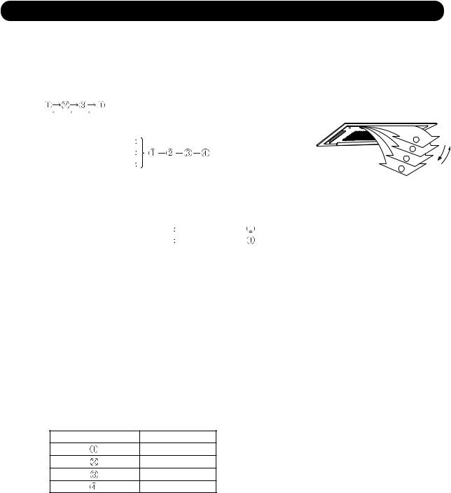
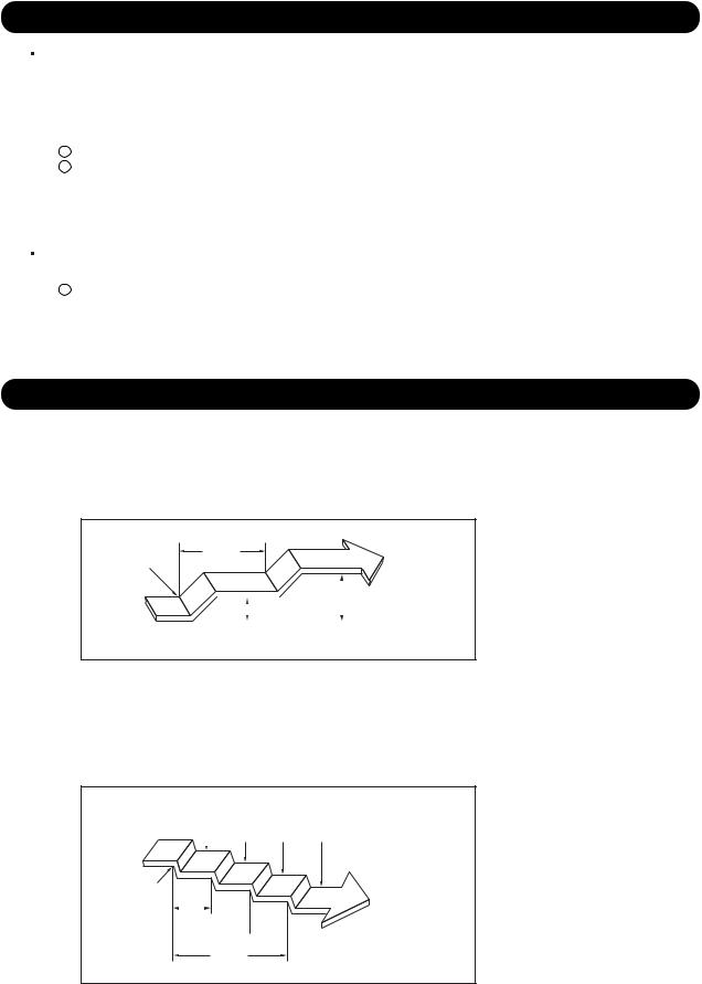
7. LOUVER CONTROL
1. VERTICAL LOUVER CONTROL
(Function Range)
Each time the button is pressed, the air direction range will change as follows:
|
(Fig.8 : Air Direction Range) |
|
(Operation Range) |
|
|
Cooling / Dry mode |
1 |
|
Heating mode |
2 |
|
3 |
||
Fan mode |
||
4 |
||
|
Use the air direction adjustments within the ranges shown above.
 The vertical airflow direction is set automatically as shown, in accordance with the type of operation selected.
Cooling / Dry / Fan mode |
Horizontal flow |
Heating mode |
Downward flow |
 For AUU18/ 24RCLX
At the start of operation if the setting louver position is  ,the setting position is set to
  after the louver moves from totally-enclosed position to
  . (Positioning Control)
 For AUU36/ 42RCLX
At the start of operation if the setting louver position is  or
or  ,the setting position is set to
  or
or  after the louver moves from totally-enclosed position to
  . (Positioning Control)
 The indoor fan motor starts after the louver reaches to the setting position.
2. SWING OPERATION
When the swing signal is received from the remote controller, the vertical louver starts to swing. The range of swing depends on the set airflow direction.
(Swinging Range)
Airflow direction set Range of swing
 to
to 
 to
to 
 to
to 
 to
to 
 When the indoor fan is either at S-Lo or Stop mode, the swinging operation is interrupted and the louver stops at the memorized position.
( Stop mode means Operation stop.)
01-08
8. COMPRESSOR CONTROL
1. OPERATION FREQUENCY RANGE
The operation frequency of the compressor is different based on the operation mode as shown in Table 7.
(Table 7 : Compressor Operation Frequency Range)
|
Cooling |
|
|
Heating |
Dry |
||
|
|
|
|
|
|
|
|
|
Min |
|
Max |
Min |
|
Max |
|
|
|
|
|
||||
|
|
|
|
|
|
|
|
AUU18RCLX |
20Hz |
|
63Hz |
20Hz |
|
87Hz |
25Hz |
AUU24RCLX |
20Hz |
|
80Hz |
20Hz |
|
87Hz |
30Hz |
AUU36RCLX |
20Hz |
|
90Hz |
20Hz |
|
95Hz |
45Hz |
AUU42RCLX |
25Hz |
|
92Hz |
23Hz |
|
92Hz |
30Hz |
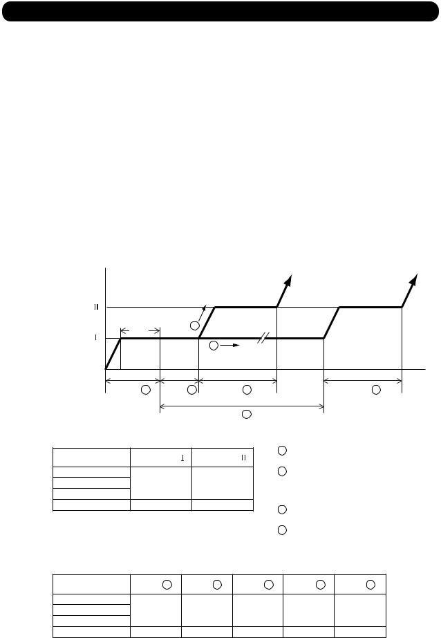
2. OPERATION FREQUENCY CONTROL AT START UP
The compressor frequency soon after the start-up is controlled as shown in Figure 9. (Fig.9 : Compressor Control at Start-up)
Frequency |
|
|
|
Hold |
1 |
|
|
|
|
|
|
Frequency |
|
2 |
|
|
|
|
|
Time A |
Time B |
Time C |
Time D |
|
|
Time E |
(Frequency) |
|
|
|
Frequency |
Frequency |
AUU18RCLX |
40Hz |
56Hz |
AUU24RCLX |
||
AUU36RCLX |
|
|
AUU42RCLX |
56Hz |
70Hz |
(Time)
For AUU18/ 24/ 36RCLX |
|
|
1 |
Discharge pipe temp. > 50°F (10°C) ,86°F (30°C) |
|
|
= |
(Heating) |
|
(Cooling) |
|
2 |
Discharge pipe temp. < 50°F (10°C) ,86°F (30°C) |
|
|
(Cooling) |
(Heating) |
For AUU42RCLX |
|
|
1 |
Discharge pipe temp. > 50°F (10°C) ,95°F (35°C) |
|
|
= |
(Heating) |
|
(Cooling) |
|
2 |
Discharge pipe temp. < 50°F (10°C) ,95°F (35°C) |
|
|
(Cooling) |
(Heating) |
|
Time A |
Time B |
Time C |
Time D |
Time E |
AUU18RCLX |
180sec |
60sec |
120sec |
120sec |
720sec |
AUU24RCLX |
|||||
AUU36RCLX |
|
|
|
|
|
AUU42RCLX |
180sec |
80sec |
180sec |
180sec |
720sec |
01-09
9. TIMER OPERATION CONTROL
9-1 Wired Remote Controller
AR-3TA14
 ON / TIMER
 OFF / TIMER
 WEEKLY TIMER
 TEMPERATURE SET BACK TIMER
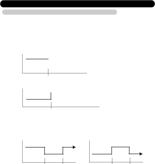
1. ON / OFF TIMER
 OFF timer : When the clock reaches the set time, the air conditioner will be turned off. Operation mode

 Stop mode
Set time of timer
 ON timer : When the clock reaches the set time, the air conditioner will be turned on.
 Operation mode
Stop mode
Set time of timer
2. WEEKLY TIMER
2-1. WEEKLY TIMER
 Use this timer function to set operating time for each day of the week.
  The weekly timer allows up to two ON and OFF time to set up per day.
Operation mode |
Operation mode |
Operation mode |
|
Stop mode |
Stop mode |
Stop mode |
|
Set time |
Set time |
Set time |
Set time |
 The operating time can be set in 30 min increments only.
 The OFF time can be carried over to next day.
 The ON timer and the OFF timer functions cannot be set with using the weekly timer. Both ON and OFF time must be set.
01-10
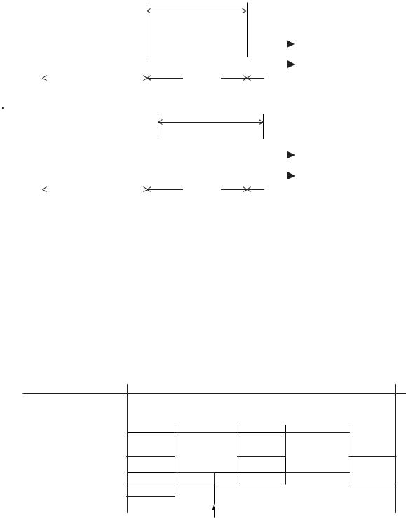
2-2. DAY OFF setting
 The DAY OFF setting is only available for days for which weekly settings already exist.
 If the operating time carries over to the next day (during a next day setting), the effective DAY OFF range will be set as shown below.
 Normal
|
|
|
|
|
|
|
|
|
|
|
|
|
DAY OFF |
|
|
|
|
||
|
|
|
|
|
|
Operation mode |
|
|
Operation mode |
|
|
|
|
||||||
|
|
Stop mode |
|
|
|
|
|
|
Stop mode |
|
|
|
|
|
Stop mode |
||||
|
|
|
|
|
|
|
|
|
|
|
|
|
|
|
|
|
|
|
|
|
|
|
|
|
|
|
|
|
|
|
|
|
|
|
|
|
|
|
|
|
|
|
|
|
|
|
|
|
|
|
|
|
|
|
|
|
|
|
|
|
|
|
|
|
|
|
|
|
|
|
|
|
|
|
|
|
|
|
|
|
|
|
|
|
Preceding day |
|
|
|
Setting day |
|
Next day |
||||||||
|
|
|
|
|
|||||||||||||||
Next day setting |
|
|
DAY OFF |
|
|
|
|
||||||||||||
|
|
|
|
|
|
|
|
|
|
|
|
|
|
|
|
|
|||
|
|
|
|
|
|
|
Operation mode |
|
|
|
Operation mode |
||||||||
|
|
Stop mode |
|
|
|
|
|
|
|
|
Stop mode |
|
|
Stop mode |
|||||
|
|
|
|
|
|
|
|
|
|
|
|
||||||||
|
|
|
|
|
|
|
|
|
|
|
|
|
|
|
|
|
|
|
|
|
|
|
|
|
|
|
|
|
|
|
|
|
|
|
|
|
|
|
|
|
|
|
|
|
|
|
|
|
|
|
|
|
|
|
|
|
|
|
|
|
|
|
|
|
|
|
|
|
|
|
|
|
|
|
|||||
|
|
|
|
|
Preceding day |
|
|
|
Setting day |
|
Next day |
||||||||
|
|
|
|
|
|
|
|
|
|||||||||||
|
|
|
|
|
|
|
|
|
|
|
|
|
|
|
|
|
|
|
|
 The DAY OFF setting can only be set one time. The DAY OFF setting is cancelled automatically after the set day has passed.
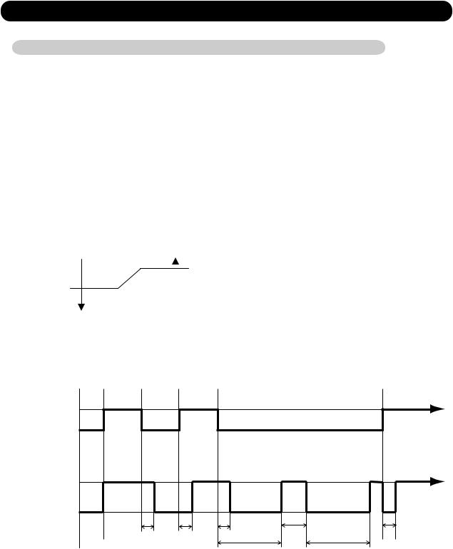
3. TEMPERATURE SET BACK TIMER
 The SET BACK timer only changes the set temperature for 7 days, it cannot be used to start or stop air conditioner operation.
 The SET BACK timer can be set to operate up to two times per day but only one temperature setting can be used.
 During the COOL/DRY mode, the air conditioner will operate at a minimum of 64°F(18°C) even if the SET BACK temperature is set to 62°F(17°C) or lower.
Case of SET BACK timer on the Cooling operation.
( Setting temperature :72°F(22°C), SET BACK temperature :80°F(26°C))
ON |
OFF |
ON |
OFF |
SET BACK setting |
|
|
|
|
||
|
|
|
|
|||
|
|
|
|
|
|
|
Operation |
80°F(26°C) |
|||||
|
|
|
|
|
||
temperature |
72°F(22°C) |
|||||
|
||||||
|
|
|
|
|
|
|
*1 |
80°F(26°C) |
|||||
Operation |
76°F(24°C) |
|||||
temperature |
||||||
72°F(22°C) |
||||||
|
||||||
|
|
|
|
|
|
|
*1: During the SET BACK function,
the setting temperature is changed. Chenge the setting temperature: 72°F(22°C)  76°F(24°C)
01-11

10. ELECTRONIC EXPANSION VALVE CONTROL
The most proper opening of the electronic expansion valve is calculated and controlled under the present operating condition based on the following values.
The compressor frequency, the temperatures detected by the discharge temperature sensor and the outdoor temperature sensor.
 The pulse range of the electronic expansion valve control is between 50 to 480 pulses.
 At the time of supplying the power to the outdoor unit, the initialization of the electronic expansion valve is operated (1000 pulses are input to the closing direction).
11. TEST OPERATION CONTROL
With Wired Remote Controller
Under the condition where the air conditioner stops, press the MASTER CONTROL button and the FAN CONTROL button simultaneously for 5 seconds or more, and the test operation control mode will appear.
During test running, " 

 " will display on the remote controller display.
Set the test operation mode, and the compressor will continue to run regardless of whatever the room temperature sensor detects.
The test operation mode is released if 60 minutes have passed after setting up the test operation.
12. PREVENT TO RESTART FOR 3 MINUTES ( 3 MINUTES ST )
The compressor won't enter operation status for 3 minutes after the compressor is stopped, even if any operation is given.
13. 4-WAY VALVE EXTENSION SELECT
At the time when the air conditioner is switched from the cooling mode to heating mode, the compressor is stopped, and the 4-way valve is switched in 3 minutes later
after the compressor stopped.
14. AUTO RESTART
When the power was interrupted by a power failure, etc. during operation, the operation contents at that time are memorized and when power is recovered, operation is automatically resumed with the memorized operation contents.
When the power is interrupted and recovered during timer operation, timer operation is canceled, but only setting time is memorized.
[Operation contents memorized when the power is interrupted]
 Operation mode
 Set temperature
 Set air flow
 Timer mode and timer time
 Air flow Direction
 Swing
Swing
 Thermistor detected position
01-12

15. PUMP DOWN ( Refrigerant collecting operation )
Perform the following procedures to collect the refrigerant when moving the indoor unit or the outdoor unit.
When the product is stopped:
1.Press the PUMP DOWN switch (SW2) on the outdoor unit.
(The LED on the outdoor unit circuit board flickers every 1second.)
2.The pump down operation (cooling operation) begins right away. After operation starts, close the 3-way valve (liquid).
3.After 2-3minutes, operation stops. Close the 3-way valve (gas) within 1minute after operations stops.
4.The LED will go out 3minutes after it stops. Disconnect the power supply after confirming that the LED has gone out.
When the product is operating:
1.Press the PUMP DOWN switch (SW2) on the outdoor unit. The LED on the outdoor unit circuit board flickers every 1second, and operation stops.
At this point, recovery has not been completed, so do not close the 2 and 3-way valves.
2.The pump down operation (cooling operation) begins after 3minutes. Close the 3-way valve (liquid) after operation starts.
3.After 2-3minutes, operation stops. Close the 3-way valve (gas) within 1minute after operations stops.
4.The LED will go out 3minutes after it stops. Disconnect the power supply after confirming that the LED has gone out.
16.COMPRESSOR PREHEATING
When the outdoor heat exchanger temperature is lower than Operation temperature (Refer to Table 8) and the heating operation has been stopped for 3 hours, power is applied to the compressor and the compressor is heated.
(By heating the compressor, warm air is quickly discharged when operation is started.)
When operation was started, and when the outdoor temperature rises to Release temperature or greater, preheating is over.
(Table 8 : Preheating Operation / Release Temperature)
|
Before 24 hour |
After 24 hour |
||
|
|
|
|
|
|
Operation |
Release |
Operation |
Release |
|
temperature |
temperature |
temperature |
temperature |
AUU18RCLX |
37.4°F |
44.6°F |
32°F |
39.2°F |
AUU24RCLX |
||||
AUU36RCLX |
(3°C) |
(7°C) |
(0°C) |
(4°C) |
AUU42RCLX |
|
|
|
|
17. DEFROST OPERATION CONTROL
1.CONDITION OF STARTING THE DEFROST OPERATION
The defrost operation starts when the outdoor heat exchanger temperature sensor detects the temperature lower than the values shown in Table 9.
(Table 9 : Condition of starting Defrost Operation)
|
|
Compressor integrating |
|
|
|
Compressor integrating |
|
operation :45min and over |
Outdoor temp. - |
Outdoor heat |
|
operation :Less than 45min. |
Less than 6 min. *1 |
After 6 min. *1 |
Outdoor heat exchanger temp. |
exchanger temp. |
|
|
|
or 10min. *2 |
or 10min. *2 |
|
|
AUU18RCLX |
|
|
|
|
|
|
|
|
|
|
|
|
AUU24RCLX |
|
|
17.6°F(-8°C) *3 |
|
|
|
|
|||||
|
|
|
|
|||||||||
AUU36RCLX |
Does not operate |
|
14°F (-10°C) *4 |
|||||||||
AUU42RCLX |
|
|
|
|
|
|
|
|
21.6 degF (12 degC) |
|
|
|
|
|
|
|
|
|
|
|
|
||||
|
|
|
|
|
|
|
|
|
|
- 4°F (-20°C) |
||
|
|
|
|
|
|
|
|
|
|
|||
|
*1. It means contiguous operation time. |
|
|
*3. Outdoor temp. > 30.2°F (-1°C) |
||||||||
|
|
|
|
|
|
|
= |
|
|
|||
|
*2. Compressor stop time: Below 20min. |
|
|
Select 6min. *4. Outdoor temp. < 30.2°F (-1°C) |
||||||||
|
|
|||||||||||
|
|
Above 20min. |
|
|
Select 10min. |
|||||||
|
|
|
||||||||||
2.CONDITION OF THE DEFROST OPERATION COMPLETION
Defrost operation is released when the conditions become as shown in Table 10.
(Table 10 : Defrost Release Condition)
|
Release Condition |
|
|
AUU18RCLX |
|
AUU24RCLX |
Outdoor heat exchanger temperature sensor value is higher than 53.6°F(12°C) or |
AUU36RCLX |
Compressor operation time has passed 15 minutes. |
|
|
AUU42RCLX |
|
|
01-13 |
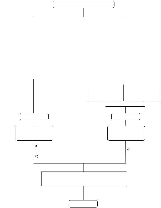
3. Defrost Flow Chart
The defrosting shall proceed by the integrating operation time and outdoor heat exchanger temperature as follows.
Heating operation start : Compressor ON
|
|
|
|
|
|
|
|
(Not defrosted for 6 or 10 minutes) |
|
||||||||
|
|
|
AUU18/ 24/ 36RCLX |
|
|
|
|
|
|
|
AUU42RCLX |
|
|||||
|
|
|
|
|
|
|
|
|
|
|
|||||||
|
Compressor integrating |
|
|
|
|
|
|
Compressor integrating |
|
|
|||||||
|
operation: |
|
|
|
|
|
|
|
|
|
operation: |
|
|
||||
|
45 minutes and over |
|
|
|
|
|
|
45 minutes and over |
|
|
|||||||
|
|
|
|
|
|
|
|
|
|
|
|
|
|
|
|
|
|
|
|
|
|
|
|
|
|
|
|
|
|
|
|
|
|
|
|
|
|
|
|
|
|
|
|
|
|
|
|
|
|
|
|
|
|
Outdoor temp. > 30.2°F |
|
|
Outdoor temp. < 30.2°F |
|
Outdoor temp. > 30.2°F |
Outdoor temp. < 30.2 F |
|
||||||||||
|
= (-1°C) |
|
|
|
(-1°C) |
|
|
= (-1°C) |
|
|
|
(-1°C) |
|
||||
|
|
|
|
|
|
|
|
|
|
|
|
|
|
|
|
|
|
Outdoor heat exchanger |
|
|
Outdoor heat exchanger |
|
Outdoor heat exchanger |
|
|
Outdoor heat exchanger |
|
|
|||||||
temperarure: |
|
|
temperarure: |
|
temperarure: |
|
|
temperarure: |
|
|
|||||||
Below 17.6°F (-8°C) |
|
|
Below 14°F (-10°C) |
|
Below 17.6°F (-8°C) |
|
|
Below 14°F (-10°C) |
|
|
|||||||
|
|
|
|
|
|
|
|
|
|
|
|
|
|
|
|
|
|
|
|
|
|
|
|
|
|
|
|
|
|
|
|
|
|
|
|
|
|
|
|
|
|
|
|
|
|
|
|
|
|
|
|
|
|
Outdoor temp - Outdoor heat exchanger temperature:
Above 21.6 degF (12 degC)
Outdoor heat exchanger temperarure:
Below - 4°F (-20°C)
Defrost start |
Defrost start |
Defrost Indicator: |
Defrost Indicator: |
[Operation lamp] |
[Operation lamp] |
9 sec ON / 1 sec OFF |
9 sec ON / 1 sec OFF |
3 sec later Compressor OFF
 3 sec later Outdoor fan motor OFF
  28 sec later 4-way valve OFF
34 sec later compressor ON (Frequency : 92 Hz)
Outdoor heat exchanger temperature: Over 53.6°F (12°C) or
Compressor ON time: Over 15 minutes
 Compressor : 30 Hz
Outdoor fan motor OFF
 4-way valve OFF
  Compressor ON (Frequency : 92 Hz)
Defrost end
01-14
18. DRAIN PUMP OPERATION
During Cooling / Dry operation
1.When the compressor starts, the drain pump starts simultaneously.
2.The drain pump operates continuously for 3 minutes after the compressor is turned off.
3.When the compressor stops by the "Indoor heat exchanger de-icing function", the drain pump is turned off in 1 hour after the compressor stops.
4.When the water level in the drain pan rises up and then the float switch functions:
1The compressor, indoor and outdoor fan motor operation are stopped.
2Drain pump operates continuously for 3 minutes after the float switch is turned off. (Almost condensing water may be drained)
5.When the float switch turns ON continuously for 3 min., "FAILURE INDICATION" operates.
6.When the float switch turns OFF within 3 min., the unit starts cooling operation.
During Heating / Fan / Stop operation
1.When the water level in the drain pan rises up and then the float switch functions:
1Drain pump operates continuously for 3 minutes after the float switch is turned off. (Almost condensing water may be drained)
2.When the float switch turns ON continuously for 3 min., "FAILURE INDICATION" operates.
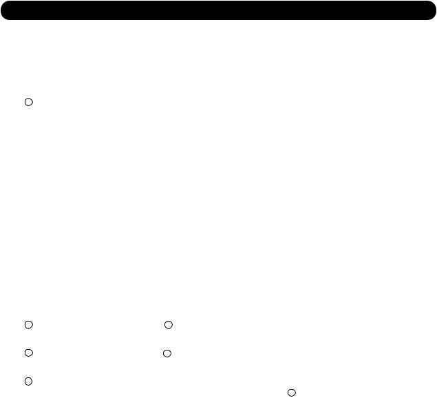
19.ENERGY SAVE FUNCTION
1.During Cooling / Dry operation:
The thermostat temperature setting increases by 1.8 degF (1 degC) as soon as the ENERGY SAVE button is pressed, and then increases by 1.8 degF (1 degC) after 1 hour later.
Afterwards, energy consumption is saved by continuing to cool or dry at a thermostat temperature of 3.6 degF (2 degC) higher than setting temperature.
ENERGY |
1hour. |
SAVE ON |
|
|
|
|
|
3.6 degF (2 degC) |
|
|
|
1.8 degF |
|||
|
|
||||
|
|
|
Setting |
||
|
|
|
|
|
|
|
|
(1 degC) |
|
||
|
|
|
temperature |
||
|
|
|
|
|
|
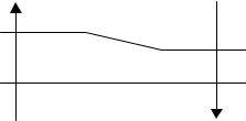
2.During Heating operation:
The thermostat temperature setting decreases by 1.8 degF (1 degC) as soon as the ENERGY SAVE button is pressed, and then decreases by another 1.8 degF (1 degC) every 30 minutes.
Afterwards, energy consumption is saved by continuing to heat at a thermostat temperature of 7.2 degF (4 degC) lower than setting temperature.
1.8degF 3.6degF 5.4degF 7.2degF
(1degC) (2degC) (3degC) (4degC) Setting  temperature
ENERGY
SAVE ON 30min.
 1 hour.
1 hour
30 min.
01-15
20. VARIOUS PROTECTIONS
1. DISCHARGE GAS TEMPERATURE OVER RISE PREVENTION CONTROL
The discharge gas thermosensor (discharge thermistor : Outdoor side) will detect discharge gas temperature.
When the discharge temperature becomes higher than Temperature  ,the compressor frequency is decreased 10 Hz, and it continues to decrease the frequency for 10 Hz every 120 seconds until the temperature becomes lower than Temperature
  .
.
When the discharge temperature becomes lower than Temperature ,the control of the compressor frequency is released.
When the discharge temperature becomes higher than Temperature |
,the compressor stops. |
||||||
When the discharge temperature becomes lower than Temperature |
,the compressor operates. |
||||||
(Table 11 : Discharge Temperature Over Rise Prevention Control / Release Temperature) |
|||||||
|
|
|
|
|
|
|
|
|
|
Temperature |
Temperature |
Temperature |
Temperature |
|
|
|
|
|
|
|
|
|
|
|
AUU18RCLX |
|
|
|
|
|
|
|
AUU24RCLX |
221°F (105°C) |
212°F (100°C) |
239°F (115°C) |
176°F (80°C) |
|
|
|
AUU36RCLX |
|
|||||
|
|
|
|
|
|
|
|
|
AUU42RCLX |
|
|
|
|
|
|
2.CURRENT RELEASE CONTROL
The compressor frequency is controlled so that the outdoor unit input current does not exceeds the current limit value that was set up with the outdoor temperature.
The compressor frequency returns to the designated frequency of the indoor unit at the time when the frequency becomes lower than the release value.
(Table 12 : Current Release Operation Value / Release Value)
[ Heating ]
AUU18RCLX |
|
|
Outdoor unit fan speed |
|
|
||
|
|
|
780 rpm |
400 rpm |
250 rpm |
220, 200 rpm |
|
T0 |
> 68°F (20°C) |
10.0A / 9.5A |
|
|
|
|
|
|
= |
|
|
10.0A / 9.5A |
8.0A / 7.5A |
6.0A / 5.5A |
|
T0 |
< 68°F (20°C) |
12.0A / 11.5A |
|
||||
|
|
|
|
||||
T0: Outdoor temperature |
|
|
|
|
|||
|
|
|
|
|
|
|
|
AUU24RCLX |
|
|
Outdoor unit fan speed |
|
|
||
|
|
|
900, 780 rpm |
400 rpm |
250 rpm |
220, 200 rpm |
|
T0 |
> 68°F (20°C) |
10.0A / 9.5A |
|
|
|
|
|
|
= |
|
|
10.0A / 9.5A |
8.0A / 7.5A |
6.0A / 5.5A |
|
T0 |
< 68°F (20°C) |
12.0A / 11.5A |
|
||||
|
|
|
|
||||
T0: Outdoor temperature |
|
|
|
|
|||
|
|
|
|
|
|
||
AUU36RCLX |
|
|
Outdoor unit fan speed |
|
|||
|
|
|
900 rpm |
780 rpm |
400 rpm |
250 rpm |
220 ,200 rpm |
T0 |
> 53.6°F (12°C) |
15.0A / 14.5A |
15.0A / 14.5A |
13.0A / 12.5A |
10.0A / 9.5A |
8.0A / 7.5A |
|
|
= |
|
|
|
|
|
|
53.6°F > T0 > 41°F |
|
|
|
|
|
||
(12°C) |
= (5°C) |
18.0A / 17.5A |
|
|
|
|
|
T0 |
< 41°F (5°C) |
|
18.0A / 17.5A |
18.0A / 17.5A |
18.0A / 17.5A |
18.0A / 17.5A |
|
T0: Outdoor temperature
01-16
AUU42RCLX |
|
Outdoor unit fan speed |
|
|||
|
|
|
|
|
|
|
|
Upper fan |
900 ,850 ,780 ,350 rpm |
|
200 rpm |
170 rpm |
150 rpm |
|
Lower fan |
850 ,780 ,750 ,350 rpm |
|
200 rpm |
170 rpm |
150 rpm |
T0 > 53.6°F (12°C) |
20.0A / 19.5A |
|
15.0A / 14.5A |
12.0A / 11.5A |
12.0A / 11.5A |
|
= |
|
|
|
|
|
|
T0 < 53.6°F (12°C) |
20.0A / 19.5A |
|
20.0A / 19.5A |
20.0A / 19.5A |
20.0A / 19.5A |
|
T0: Outdoor temperature
[ Cooling ]
AUU18RCLX |
|
|
|
|
Outdoor unit fan speed |
|
|
||
|
|
|
|
|
780 rpm |
400 rpm |
250 rpm |
220, 200 rpm |
|
T0 > 113°F (45°C) |
8.0A / 7.5A |
8.0A / 7.5A |
5.0A / 4.5A |
4.0A / 3.5A |
|
||||
= |
|
|
|
|
|
|
|
|
|
113°F > T0 > 77°F |
|
|
|
|
|
||||
(45°C) |
=(25°C) |
10.0A / 9.5A |
|
|
|
|
|||
77°F > T0 > 66.2°F |
12.0A / 11.5A |
12.0A / 11.5A |
7.0A / 6.5A |
|
|
||||
(25°C) |
= |
(19°C) |
|
|
|||||
|
|
|
|
|
|
||||
66.2°F > T0 > 55.4°F |
|
|
8.0A / 7.5A |
|
|
||||
(19°C) |
|
= |
(13°C) |
|
|
|
|
||
|
|
|
|
|
|
|
|||
55.4°F > T0 > 44.6°F |
|
|
8.5A / 8.0A |
5.0A / 4.5A |
|
||||
(13°C) |
|
= |
(7°C) |
|
|
|
|||
|
|
|
|
|
|
|
|||
44.6°F > T0 > 32°F |
|
|
9.0A / 8.5A |
6.5A / 6.0A |
|
||||
(7°C) |
|
= |
(0°C) |
|
|
|
|||
|
|
|
|
|
|
|
|||
T0 < 32°F (0°C) |
|
|
|
7.5A / 7.0A |
|
||||
T0: Outdoor temperature |
|
|
|
|
|||||
|
|
|
|
|
|
|
|
||
AUU24RCLX |
|
|
|
|
Outdoor unit fan speed |
|
|
||
|
|
|
|
|
900 ,850 rpm |
780 rpm |
400 rpm |
250 rpm |
220, 200 rpm |
T0 > 113°F (45°C) |
8.0A / 7.5A |
8.0A / 7.5A |
8.0A / 7.5A |
5.0A / 4.5A |
4.0A / 3.5A |
||||
= |
|
|
|
|
|
|
|
|
|
113°F > T0 > 100.4°F |
|
|
|
|
|
||||
(45°C) |
= |
(38°C) |
10.0A / 9.5A |
10.0A / 9.5A |
|
|
|
||
100.4°F > T0 > 77°F |
12.0A / 11.5A |
|
|
|
|
||||
(38°C) |
|
= |
(25°C) |
|
|
|
|
||
|
|
|
|
|
|
|
|
||
77°F > T0 > 66.2°F |
|
12.0A / 11.5A |
12.0A / 11.5A |
7.0A / 6.5A |
|
||||
(25°C) |
= |
(19°C) |
|
|
|||||
|
|
|
|
|
|
||||
66.2°F > T0 > 55.4°F |
|
|
|
|
|
||||
(19°C) |
|
= |
(13°C) |
|
|
|
8.0A / 7.5A |
|
|
55.4°F > T0 > 44.6°F |
|
|
|
|
|
||||
(13°C) |
|
= |
(7°C) |
|
|
|
8.5A / 8.0A |
5.0A / 4.5A |
|
44.6°F > T0 > 32°F |
|
|
|
9.0A / 8.5A |
6.5A / 6.0A |
||||
(7°C) |
|
= |
(0°C) |
|
|
|
|
|
|
T0 < 32°F (0°C) |
|
|
|
|
7.5A / 7.0A |
||||
T0: Outdoor temperature |
|
|
|
|
|||||
01-17
AUU36RCLX |
|
|
Outdoor unit fan speed |
|
|
|||||
|
|
|
|
900 ,850 rpm |
780 rpm |
400 rpm |
250 rpm |
220, 200 rpm |
||
T0 > 113°F (45°C) |
10.0A / 9.5A |
10.0A / 9.5A |
10.0A / 9.5A |
7.0A / 6.5A |
5.5A / 5.0A |
|||||
= |
|
|
|
|
|
|
|
|
|
|
113°F > T0 > 100.4°F |
|
|
|
|
|
|
|
|||
(45°C) |
= |
(38°C) |
14.0A / 13.5A |
14.0A / 13.5A |
|
|
|
|
||
100.4°F > T0 > 66.2°F |
18.0A / 17.5A |
|
|
|
|
|
|
|||
(38°C) |
= |
|
|
|
|
|
|
|||
(19°C) |
|
|
|
|
|
|
|
|||
66.2°F > T0 > 55.4°F |
|
15.0A / 14.5A |
15.0A / 14.5A |
|
|
|||||
(19°C) |
= |
(13°C) |
|
|
7.0A / 6.5A |
|||||
55.4°F > T0 > 44.6°F |
|
|
|
|
|
|
|
|||
(13°C) |
= |
(7°C) |
|
|
|
|
|
12.0A / 11.5A |
|
|
44.6°F > T0 > 32°F |
|
|
|
|
|
|
|
|||
(7°C) |
= |
(0°C) |
|
|
|
|
|
|
|
|
T0 < 32°F (0°C) |
|
|
|
|
|
|
9.5A / 9.0A |
|||
T0: Outdoor temperature |
|
|
|
|
|
|
||||
|
|
|
|
|
|
|
|
|
||
AUU42RCLX |
|
|
Outdoor unit fan speed |
|
|
|||||
|
|
Upper fan |
850 rpm |
780 rpm |
350 rpm |
400 rpm |
350, 300 rpm |
|||
|
|
Lower fan |
750 rpm |
780 rpm |
350 rpm |
0 rpm |
0 rpm |
|||
T0 > 113°F (45°C) |
12.0A / 11.5A |
12.0A / 11.5A |
12.0A / 11.5A |
12.0A / 11.5A |
12.0A / 11.5A |
|||||
= |
|
|
|
|
|
|
|
|
|
|
113°F > T0 > 87.8°F |
|
|
|
|
|
|
|
|||
(45°C) |
= |
(31°C) |
20.0A / 19.5A |
20.0A / 19.5A |
|
|
|
|
||
87.8°F > T0 > 77°F |
|
|
|
18.0A / 17.5A |
|
|
||||
(31°C) |
= |
(25°C) |
|
|
|
|
|
|||
|
|
|
|
|
|
|
|
|
||
77°F > T0 > 66.2°F |
|
|
|
|
|
18.0A / 17.5A |
|
|||
(25°C) |
= (19°C) |
|
|
|
|
|
|
|||
66.2°F > T0 > 55.4°F |
|
|
|
|
|
|
|
|||
(19°C) |
= |
(13°C) |
|
|
|
20.0A / 19.5A |
|
15.0A / 14.5A |
||
T0 < 55.4°F (13°C) |
|
|
|
|
|
|
18.0A / 17.5A |
|||
T0: Outdoor temperature |
|
|
|
|
|
|
||||
01-18

3.ANTI-FREEZING CONTROL (Cooling mode)
The compressor frequency decreases on cooling mode when the indoor heat exchanger temperature sensor detects the temperature lower than 37.4°F (3°C).
Then, the anti-freezing control is released when it becomes higher than 42.8°F (6°C).
(Fig 10 : Anti-freezing Protection Operation / Release Temperature)
Indoor heat exchanger temperature
The compressor frequency is
decreased 10Hz every 120seconds.
37.4°F
(3°C)
Hold
42.8°F
(6°C) Compressor OFF : Hold
Compressor ON : Release of protection
53.6°F
(12°C)
Release of protection
When the compressor frequency becomes lower than minimum frequency, the compressor operates at minimum frequency.
If the indoor heat exchanger temperature sensor detects the temperature lower than 37.4°F (3°C) after 2minutes upon operating the compressor at minimum frequency, the compressor stops.
4.COOLING PRESSURE OVER RISE PROTECTION
When the outdoor unit heat exchange sensor temperature rises to 158.9°F (70.5°C) or greater, the compressor is stopped and error display is indicated.
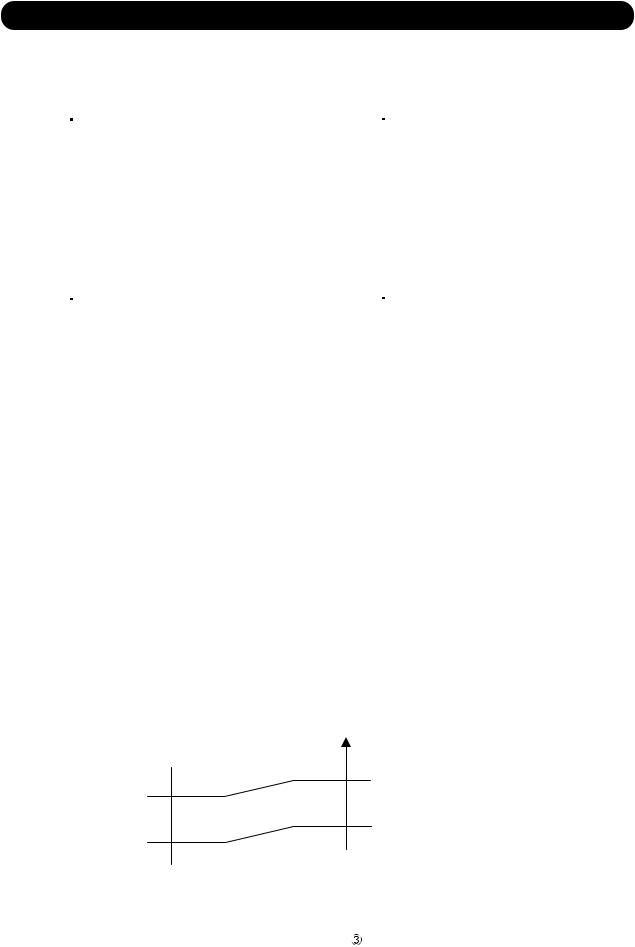
5.HIGH TEMPERATURE RELEASE CONTROL ( HEATING MODE )
On heating mode, the compressor frequency is controlled as following based on the detection value of the indoor heat exchanger temperature sensor.
(Fig 11 : Heating Overload Protection Control)
Indoor heat exchange temperature
Compressor is OFF
145.4°F
(63°C)
The compressor frequency is decreased 10Hz every 60seconds.
129.2°F
(54°C)
Hold
122°F
(50°C)
Compressor OFF : Release of protection
Compressor ON :
The compressor frequency is increased 10Hz every 60seconds.
01-19

R410A
CASSETTE type
INVERTER
2 . TROUBLE SHOOTING
2. TROUBLESHOOTING
2-1 ERROR DISPLAY
2-1-1 WIRED REMOTE CONTROLLER DISPLAY
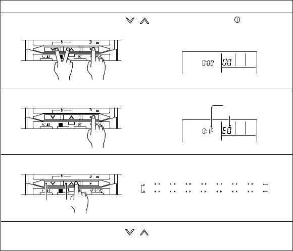
1.SELF - DIAGNOSIS
When the error indication "E:EE" is displayed, inspection of the air conditioning system is necessary. Please consult authoilzed servise personnel.
Run [Self-Diagnosis] if [E:EE] flashes on the clock display of the remote controller.
Display |
|
|
|
|
|
Error code |
SU MO |
TU WE TH FR |
SA |
|
|
|
SU MO TU WE TH FR SA |
|
|
|
|
|
|
Ex. Self-diagnosis |
|
DAY |
|
|
DAY |
|
|
CLOCK ADJUST |
DAY OFF |
ENERGY |
CLOCK ADJUST |
DAY OFF |
ENERGY |
THERMO |
SET BACK |
|
SAVE |
SET BACK |
SET |
SAVE |
SENSOR |
DELETE |
SET |
|
DELETE |
SET |
|
|
1. Stop the air conditioner operation. |
|
|
|
|
||
2. Press the SET TEMPERATURE buttons |
and |
simultaneously for 5 seconds or more |
||||
to start the self-diagnosis. |
|
|
|
|
||
3. Press the SET TEMPERATURE buttons and or there is no key input for 20 seconds to stop the
simultaneously for 5 seconds or more self-diagnosis.
Error code |
Error contents |
|
Trouble |
||
|
shooting |
||||
|
|
|
|
|
|
|
|
|
|
|
|
|
Communication error (indoor unit |
|
|
remote control) |
1 |
|
|
||||
|
Communication error (Serial reverse transfer error) |
2 |
|||
|
Room temperature sensor open |
|
3 |
||
|
Room temperature sensor short-circuited |
||||
|
|
||||
|
Indoor heat exchanger temperature sensor open |
4 |
|||
|
Indoor heat exchanger temperature sensor short-circuited |
||||
|
|
||||
|
Outdoor heat exchanger temperature sensor error |
5 |
|||
|
Water drain abnormal |
|
6 |
||
|
Outdoor temperature sensor error |
|
7 |
||
|
Outdoor discharge pipe temperature sensor error |
8 |
|||
|
Indoor EEPROM abnormal (Model No.) |
9 |
|||
|
Indoor fan motor abnormal |
|
10 |
||
|
Outdoor communication signal error (Forward transfer signal error) |
11 |
|||
|
Compressor temperature sensor error |
|
12 |
||
|
Pressure switch error |
|
13 |
||
|
IPM error |
|
14 |
||
|
CT error |
|
15 |
||
|
Active filter module (AFM) error |
|
16 |
||
|
Compressor rotor location cannot detect (permanent stop) |
17 |
|||
|
Outdoor unit fan motor error |
|
18 |
||
02-01
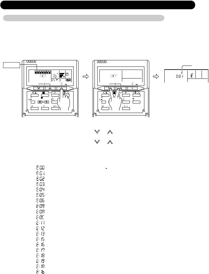
2. ERROR CODE HISTORY DISPLAY
Up to 16 memorized error codes may be displayed for the indoor unit connected to the remote controller.
1. Stop the air conditioner operation.
2. Press the SET TEMPERATURE buttons , |
and the START/STOP button simultaneously |
for 5 seconds or more to start the self-diagnosis. |
|
DAY |
SU MO TU WE TH FR SA |
|
3. Press the START/STOP button.
DAY |
SU MO TU WE TH FR SA |
|
Error code
Error history number
4. Press the SET TEMPERATURE button to select the error history number.
|
DAY |
Lower |
Raise |
0 |
|
|
1 |
|
|
|
2 ı |
|
3 |
|
|
4 |
|
5 |
|
6 |
|
7 |
||||||
|
|
|
|
|
|
|
|
|||||||||||||||||
F |
|
|
|
E |
|
|
|
d |
|
|
c |
|
|
|
b |
|
|
A |
|
9 |
|
8 |
||
|
|
|
|
|
|
|
|
|
|
|||||||||||||||
|
|
|
|
|
|
|
|
|
|
|
|
|||||||||||||
5. Press the SET TEMPERATURE buttons , and START/STOP button simultaneously for 5 seconds or more or there is no key input for 20 seconds to stop the display.
02-02
2-1-2 OUTDOOR UNIT DISPLAY
1. ERROR DISPLAY
Error contents |
LED Flashing |
Display |
Trouble |
|
Pattern |
priority |
shooting |
||
|
||||
Outdoor communication signal error |
1 time flash |
1 |
11 |
|
(Forward transfer signal error) |
||||
|
|
|
||
Outdoor discharge pipe temperature sensor error |
2 times blink |
2 |
8 |
|
Outdoor heat exchanger temperature sensor error |
3 times blink |
3 |
5 |
|
Outdoor temperature sensor error |
4 times blink |
4 |
7 |
|
Compressor temperature sensor error |
7 times blink |
5 |
12 |
|
Heat sink temperature sensor error |
8 times blink |
6 |
19 |
|
Pressure switch abnormal |
9 times blink |
7 |
13 |
|
IPM error |
12 times blink |
8 |
14 |
|
Compressor rotor location cannot detect |
13 times blink |
9 |
17 |
|
Compressor Start-up error |
14 times blink |
10 |
20 |
|
Outdoor unit fan motor error (upper fan) |
15 times blink |
11 |
18 |
|
Outdoor unit fan motor error (lower fan) |
16 times blink |
12 |
||
|
2.ERROR DISPLAY METHOD
Outdoor LED Blink (1 to 16 times) 0.5sec ON / 0.5sec OFF blinking
|
0.5sec |
0.5sec |
|
2sec |
|
|
|
|
|||||||||
ON |
|
|
|
|
|
|
|
|
|
|
|
|
|
|
|
|
|
|
|
|
|
|
|
|
|
|
|
|
|
|
|
|
|
||
|
|
|
|
|
|
|
|
|
|
|
|
|
|
|
|
||
OFF |
|
|
|
|
|
|
|
|
|
|
|
|
|
|
|
|
|
|
|
|
|
|
|
|
|
|
|
|
|
|
|
|
|
|
|
3. NORMAL OPERATION DISPLAY
Operation |
LED Blinking Pattern |
Normal operation |
Continuously lighting |
Protected operation |
5sec ON / 1sec OFF |
Pump down operation |
1sec ON / 1sec OFF |
02-03
2-2 TROUBLE SHOOTING WITH ERROR CODE
Trouble shooting 1 |
Indicate or Display: |
|||
INDOOR UNIT Error Method: |
Indoor Unit |
: No LED |
||
Communication Error |
Outdoor Unit |
: No indication |
||
(Indoor unit |
|
Remote control) |
ERROR CODE : E : 00 |
|
|
||||
Detective Actuators: |
Detective details: |
|||
Indoor unit controller PCB circuit Wired Remote Control
When the indoor unit cannot receive the signal from Wired Remote more than 10seconds after power ON, or the indoor unit cannot receive the signal more than 1minute during normal operation.
Forecast of Cause:
1. Terminal connection abnormal 2. Wired Remote Control failure 3. Controller PCB failure
Check Point 1 : Check the connection of terminal
After turning off the power, check & correct the followings.
Check the connection of terminal between remote control and Indoor unit, and check if there is a disconnection of the cable.
OK
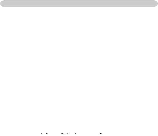
Check Point 2 : Check Remote Control and Controller PCB
Check Voltage at CN17 of Controller PCB. (Power supply to Remote Control) |
|
>> If it is DC12V, Remote Control is failure. (Controller PCB is normal) |
>> Replace Remote Control |
>> If it is DC 0V, Controller PCB is failure. (Check Remote Control once again) |
>> Replace Controller PCB |
 Upon correcting the removed connector or mis-wiring, reset the power.
02-04

Trouble shooting 2 |
OUTDOOR UNIT Error Method: |
Communication Error |
(Serial Reverse Transfer Error) |
Detective Actuators:
Outdoor Unit Main PCB Circuit
Active Filter Module
Forecast of Cause:
Indicateicate ororDisplay:Display:
Indoor Unit |
: No LED |
Outdoor Unit |
: No indication |
ERROR CODE : E : 01
Detective details:
When the indoor unit cannot receive the serial signal from Outdoor unit more than 10seconds.
1. Connection failure 2. External cause 3. Main PCB failure 4. Active Filter Module failure
Check Point 1-1 : Reset the power and operate
Does Error indication show again?
YES
Check Point 2 : Check Connection
Check any loose or removed connection line of Indoor unit and Outdoor unit.
>>If there is an abnormal condition, correct it by referring to Installation Manual or Data & Technical Manual.
Check connection between Outdoor Unit Main PCB and Filter PCB.
(If there is loose connector or open cable)
OK
NO
Check Point 1-2:
Check external cause such as noise
Check the complete insulation of the grounding.
Check if there is any equipment that causes harmonic wave near the power cable (Neon light bulb or any electronic equipment which causes harmonic wave).
Check Point 3 : Check the voltage of power supply
Check the voltage of power supply
>> Check if AC208 - 230V appears at Outdoor Unit Terminal L - N.
OK
Check Point 4 : Check Serial Signal (Reverse Transfer Signal)
Check Serial Signal (Reverse Transfer Signal)
>>Check if Indicated value swings between AC70V and AC130V at Outdoor Unit Terminal 1 - 3.
>>If it is abnormal, Check Active Filter Module. (PARTS INFORMATION 3)
>>If Active Filter Module is abnormal, replace it.
>>If Active Filter Module is normal, replace Main PCB.
WHITE |
N |
BLACK |
L |
RED |
3 |
WHITE |
2 |
BLACK |
1 |
+ |
- |
02-05
Trouble shooting 3 INDOOR UNIT Error Method:
Room Temperature Sensor Error
Detective Actuators:
Indoor Unit Controller PCB Circuit
Room Temperature Thermistor
Forecast of Cause :
Indicate or Display:
Indoor Unit |
: No LED |
Outdoor Unit |
: No indication |
ERROR CODE : E : 02 / 03
Detective details:
When Room Temperature Thermistor open or short-circuit is detected at power ON.
1. Connector connection failure 2.Thermistor failure 3. Controller PCB failure
Check Point 1 : Check connection of Connector
Check if connector is removed. Check erroneous connection. Check if thermistor cable is open.
>>Upon correcting the removed connector or mis-wiring, reset the power.
OK
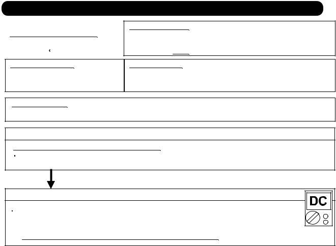
Check Pointi 2 :: Remove connector and check Thermistor resistance value
Thermistor Characteristics (Approx. value)
Temperature |
|
32°F |
41°F |
50°F |
59°F |
68°F |
77°F |
86°F |
95°F |
|
|
(0°C) |
(5°C) |
(10°C) |
(15°C) |
(20°C) |
(25°C) |
(30°C) |
(35°C) |
|
|
|
|
|
|
|
|
|
|
Resistance Value (k |
) |
33.6 |
25.9 |
20.2 |
15.8 |
12.5 |
10.0 |
8.04 |
6.51 |
|
|
|
|
|
|
|
|
|
|
|
|
|
|
|
|
|
|
|
|
Temperature |
|
104°F |
113°F |
122°F |
|
|
|
|
|
|
|
(40°C) |
(45°C) |
(50°C) |
|
|
|
|
|
|
|
|
|
|
|
|
|
|
|
Resistance Value (k |
) |
5.30 |
4.35 |
3.59 |
|
|
|
|
|
|
|
|
|
|
|
|
|
|
|
 If Thermistor is either open or shorted, replace it and reset the power.
OK
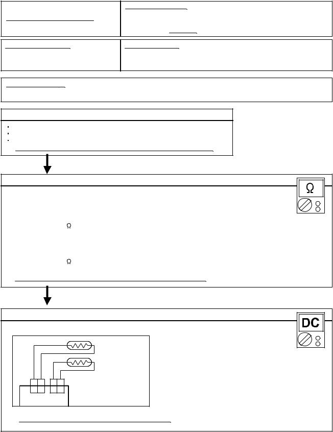
Check Pointi 3 :: Check voltage of Controller PCB (DC5.0V)
Make sure circuit diagram of indoor unit and check terminal voltage at Thermistor (DC5.0V)
GRAY GRAY |
BLACK BLACK |
|
1 |
2 |
1 2 |
1 |
2 |
1 2 |
CN7 CN8
THERMISTOR (PIPE TEMP.)
THERMISTOR (ROOM TEMP.)
 If the voltage does not appear, replace Controller PCB.
02-06
 Loading...