


 Loading...
AN706-00044-1v0-E
32-BIT MICROCONTROLLER
MB9B100A/MB9B300A/MB9B400A/MB9B500A Series
FM3 family inverter solution
GUI User Manual
TM
ARM and Cortex-M3 are the trademarks of ARM Limited in the EU and other countries.

AN706-00044-1v0-E
All Rights Reserved.
The contents of this document are subject to change without notice. Customers are advised to consult with FUJITSU sales representatives before ordering.
The information, such as descriptions of function and application circuit examples, in this document are presented solely for the purpose of reference to show examples of operations and uses of Fujitsu semiconductor device; Fujitsu does not warrant proper operation of the device with respect to use based on such information. When you develop equipment incorporating the device based on such information, you must assume any responsibility arising out of such use of the information. Fujitsu assumes no liability for any damages whatsoever arising out of the use of the information.
Any information in this document, including descriptions of function and schematic diagrams, shall not be construed as license of the use or exercise of any intellectual property right, such as patent right or copyright, or any other right of Fujitsu or any third party or does Fujitsu warrant non-infringement of any third-party’s intellectual property right or other right by using such information. Fujitsu assumes no liability for any infringement of the intellectual property rights or other rights of third parties which would result from the use of information contained herein.
The products described in this document are designed, developed and manufactured as contemplated for general use, including without limitation, ordinary industrial use, general office use, personal use, and household use, but are not designed, developed and manufactured as contemplated (1) for use accompanying fatal risks or dangers that, unless extremely high safety is secured, could have a serious effect to the public, and could lead directly to death, personal injury, severe physical damage or other loss (i.e., nuclear reaction control in nuclear facility, aircraft flight control, air traffic control, mass transport control, medical life support system, missile launch control in weapon system), or (2) for use requiring extremely high reliability (i.e., submersible repeater and artificial satellite).
Please note that Fujitsu will not be liable against you and/or any third party for any claims or damages arising in connection with above-mentioned uses of the products.
Any semiconductor devices have an inherent chance of failure. You must protect against injury, damage or loss from such failures by incorporating safety design measures into your facility and equipment such as redundancy, fire protection, and prevention of over-current levels and other abnormal operating conditions. If any products described in this document represent goods or technologies subject to certain restrictions on export under the Foreign Exchange and Foreign Trade Law of Japan, the prior authorization by Japanese government will be required for export of those products from Japan.
The company names and brand names herein are the trademarks or registered trademarks of their respective owners.
Copyright© 2011 FUJITSU SEMICONDUCTOR LIMITED all rights reserved
1

AN706-00044-1v0-E
Revision History
Rev |
Date |
Remark |
|
|
|
1.0 |
Jul. 14, 2011 |
First Edition |
|
|
|
|
|
|
2

AN706-00044-1v0-E
Table of Contents
Revision History.................................................................................................................... |
2 |
||
Table of Contents.................................................................................................................. |
3 |
||
1 |
Introduction.................................................................................................................... |
4 |
|
2 |
System requirements..................................................................................................... |
5 |
|
|
2.1 |
Supported Operating Systems: .............................................................................. |
5 |
|
2.2 |
Supported software environment............................................................................ |
5 |
3 |
Install GUI...................................................................................................................... |
6 |
|
4 |
Simply install steps about the communication Driver..................................................... |
7 |
|
|
4.1 |
To install FTDI driver in Windows XP...................................................................... |
7 |
|
4.2 |
To install FTDI driver in Windows 7 ........................................................................ |
7 |
5 |
How to use the GUI ....................................................................................................... |
8 |
|
|
5.1 |
Overview ................................................................................................................ |
8 |
|
5.2 |
PC Connection with the hardware .......................................................................... |
8 |
|
5.3 |
GUI Startup............................................................................................................. |
9 |
|
5.4 |
GUI software windows’ name and function........................................................... |
10 |
5.4.1 |
Inverter Platform software introduce.............................................................. |
10 |
5.4.2 |
Main window ................................................................................................. |
11 |
5.4.3 |
Function/parameter settings window ............................................................. |
13 |
5.4.4 |
Signal selection window ................................................................................ |
17 |
5.4.5 |
Graphic window............................................................................................. |
19 |
5.4.6 |
Variable window ............................................................................................ |
23 |
5.4.7 |
Constant window ........................................................................................... |
24 |
5.5 Example of total operating Procedure .................................................................. |
25 |
|
5.5.1 |
Hardware preparation.................................................................................... |
25 |
5.5.2 |
GUI software operating step.......................................................................... |
25 |
6 Appendix...................................................................................................................... |
34 |
|
6.1 Particular Install steps about the communication Driver ....................................... |
34 |
|
6.1.1 |
To install FTDI device in Windows XP ........................................................... |
34 |
6.1.2 |
FTDI Drivers Installation guide for Windows 7............................................... |
42 |
6.2 Motor parameter item ........................................................................................... |
55 |
|
3

AN706-00044-1v0-E
1 Introduction
This user manual describes how to use FUJITSU’S FM3 Inverter Platform GUI. In Chapter 2, it explains system requirements for the GUI software.
In Chapter 3, it explains how to install the GUI software.
In Chapter 4, it explains how to install the communication driver (FTDI). In Chapter 5, it explains how to use the GUI.
4

AN706-00044-1v0-E
2 System requirements
The GUI software supported environment on PC
2.1Supported Operating Systems:
Windows Server 2003, Windows Server 2008, Windows Vista, Windows XP, Windows 7
1.Microsoft Windows XP Service Pack 2 or Service Pack 3 Minimum of 192 MB of RAM (384 MB preferred)
At least a 1 GHz processor (1.6 GHz preferred)
2.Microsoft Windows Vista or Windows Vista SP1 Minimum of 768 MB of RAM (1 GB preferred)
At least a 1.6 GHz processor (2.2 GHz preferred)
3.Microsoft Windows Server 2003 Service Pack 2 or Windows Server 2008 Minimum of 768 MB of RAM (1 GB preferred)
At least a 1.6 GHz processor (2.2 GHz preferred)
2.2Supported software environment.
Microsoft.NET Framework 2.0(over this version preferred)
Note: This software is necessary.
5

AN706-00044-1v0-E
3 Install GUI
Install the GUI software in your PC
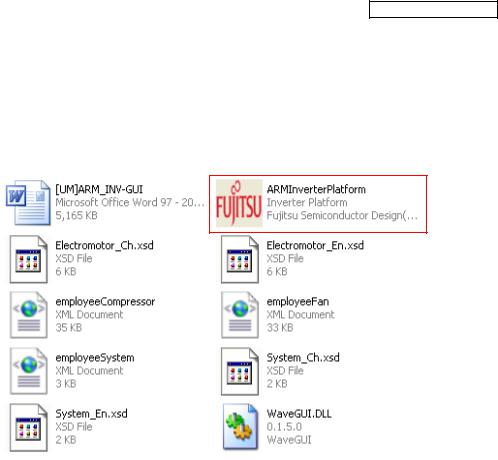
This FUJITSU’S FM3 Inverter Platform GUI is given by compressed file, please copy and unzip the “FUJITSU’S FM3 Inverter platform GUI.zip” file to your PC. Then, you will find 10 files in the “FUJITSU’S FM3 Inverter platform GUI” folder.
|
|
Table 3-1: GUI files |
|
|
|
|
|
|
File name |
|
Remarks |
1 |
ARMInverterPlatform.exe |
|
the Software Executable file |
|
|
|
|
2 |
Electromotor_Ch.xsd |
|
|
|
|
|
|
3 |
Electromotor_En.xsd |
|
Parameter type file |
|
|
|
|
4 |
System_Ch.xsd |
|
|
|
|
||
|
|
|
|
5 |
System_En.xsd |
|
|
|
|
|
|
6 |
employeeCompressor.xml |
|
the palm parameter database |
|
|
|
|
7 |
employeeFan.xml |
|
|
|
(Configuration file) |
||
|
|
|
|
8 |
employeeSystem.xml |
|
|
|
|
||
|
|
|
|
9 |
WaveGUI.DLL |
|
wave widget dynamic link libraries |
|
|
|
|
10 |
[UM]ARM_INV-GUI.doc |
|
User manual |
|
|
|
|
6

AN706-00044-1v0-E
4 Simply install steps about the communication Driver
A simply install steps for the FTDI.
4.1 To install FTDI driver in Windows XP Simply install steps:
1.Connect the FTDI device (board) to a USB port on the PC.
2.New Hardware Wizard will launch.
3.Select "Install from a list or specific location (Advanced)".
4.Select "Search for the best driver in these locations" and enter the file path in the combo-box.
5.Install the “ftd2xxx.dll”file in the PC.
6.The same way to install the “ftserui2.dll” file in the PC.
The particular install steps, please refer Chapter 6.1.1
4.2To install FTDI driver in Windows 7
1.Connect the FTDI device (board) to a USB port on the PC.
2.Open Control Panel, select Hardware and Setting, Device Manager, and Other Devices, then click right button on the mouse, select Update Driver Software, select the second option to browse manually, select address of drivers have been saved and finally install the “ftd2xxx.dll ”in the PC.
3.The same way to install the “ftserui2.dll” file in the PC.
The particular install steps, please refer Chapter 6.1.2
7
AN706-00044-1v0-E
5 How to use the GUI
Introduce the GUI software
5.1Overview
This GUI use to cooperate with the FUJITSU’S FM3 inverter platform, customer can use this GUI to:
1.Real-time control the motor and PFC module function;
2.Real-time setting the motor functions and parameters;
3.Real-time observation of motor running state, used variables and current waveform shape.
4.Real-time observation of system information, and so on.
It’s means that the GUI is ordered to help customer debug the inverter platform and motor rotation.
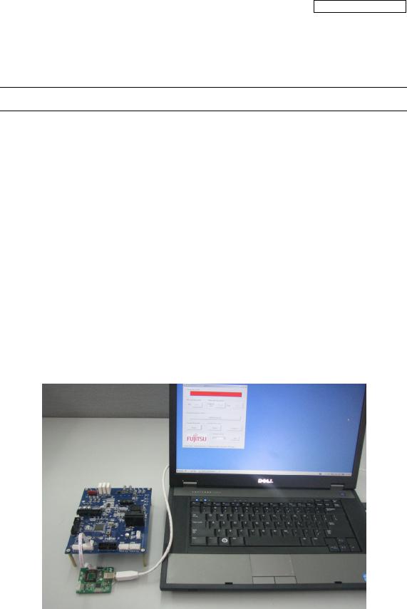
5.2PC Connection with the hardware
The hardware need to use Serial Port connected FTDI, and FTDI connects with PC use USB port. Please refer
Figure 5-1: Connection
8
AN706-00044-1v0-E
5.3GUI Startup
Open the folder; double click the “ARMInverterPlatform.exe” to run the software, as Figure 5.2.
Figure 5-2: GUI files
9
AN706-00044-1v0-E
5.4GUI software windows’ name and function
5.4.1Inverter Platform software introduce.
-Name: Platform
-Function: language setting, contain all function windows, and so on.
Figure 5-3: Inverter Platform
10
AN706-00044-1v0-E
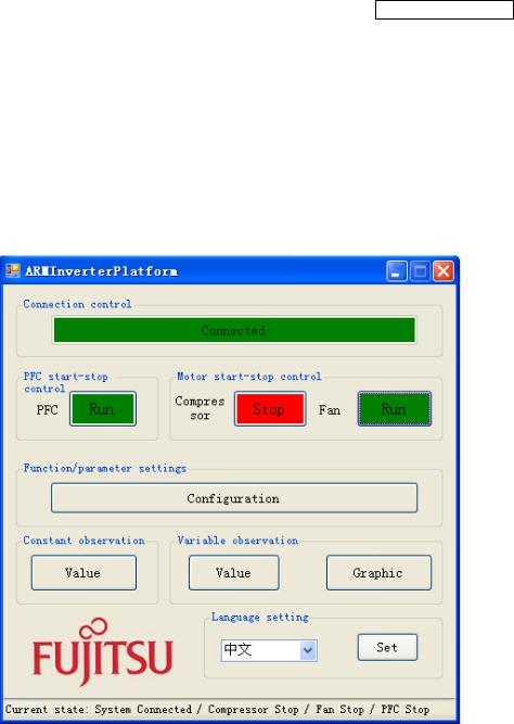
5.4.2Main window
- Name : |
Main window |
-Function: connect control, start/stop control, function/parameter setting, Constant/variable observation, language setting, and current state.
|
|
1 |
|
|
|
2 |
3 |
4 |
|
|
|
5 |
|
|
|
6 |
7 |
8 |
|
|
|
|
|
9 |
|
|
|
|
10 |
|
|
Figure 5-4: main window |
|
|
|
Table 5-1: main window function |
|
||
|
|
|
|
|
|
Name of button |
|
Specification |
|
1 |
Connect |
|
Init the FTDI and Connect with MCU |
|
|
|
|
|
|
2 |
PFC start-stop control |
|
Operate PFC module function start / stop |
|
|
|
|
|
|
3 |
Compressor start-stop control |
|
Operate compressor start/stop |
|
|
|
|
|
|
4 |
Fan start-stop control |
|
Operate fan start / stop |
|
|
|
|
|
|
5 |
Function/Parameter setting |
|
Set motor function and parameter. |
|
|
If the button is pushed, the configuration window opens. |
|||
|
|
|
(See Chapter 4.4.2) |
|
|
|
|
|
|
11

AN706-00044-1v0-E
6 |
Constant observation |
Observe system state, motor state, motor parameter, and so on. |
If the button is pushed, the constant window opens. |
||
|
|
(See Chapter 4.4.6) |
|
|
|
7 |
Variable observation |
Observe measure value with variable. |
If the button is pushed, the variable window opens. |
||
|
|
(See Chapter4.4.5) |
|
|
|
8 |
Graphic |
Observe measure value with wave. |
If the button is pushed, Figure4-3 of the graphic window opens. |
||
|
|
(See Chapter 4.4.4) |
9 |
Language setting |
Set system language Chinese or English |
|
|
|
10 |
System current state |
Show the current state: connect, PFC, compressor, Fan |
|
|
|
-Notice:
-The hardware cannot be mounted Fan motor. So the function is ignored.
-The hardware is mounted PFC function. And the firmware control PFC function automatically. So, GUI cannot control the PFC function.
(If you push green PFC function button in running compressor, the function is ignored. After that, if you push red PFC function button again, the compressor stops.)
12

AN706-00044-1v0-E
5.4.3Function/parameter settings window
- Name : |
function/parameter settings window |
-Function: motor selection, motor function setting and comeback default, motor parameter setting and comeback default, save config file, load config file.
1
2
3 6
4
5
Figure 5-5: setting window
13

AN706-00044-1v0-E
|
|
Table 5-2: setting window function |
|
|
|
|
|
|
Name of area |
|
Specification |
1 |
Motor selection |
|
Select which motor need to set, compressor / fan |
|
|
|
|
2 |
Motor function set |
|
Function set |
|
|
|
|
3 |
Motor parameter set |
|
Parameter set |
|
|
|
|
4 |
Parameter type selection |
|
Selection motor parameter type |
|
|
|
|
5 |
Config file save and load |
|
Save and load config file |
|
|
|
|
6 |
Set and default button |
|
Set/default the parameter and function to hardware |
|
|
|
|
-Notice:
-The hardware cannot be mounted Fan motor. So the function is ignored.
-Some parameters cannot change the value. (In that case, the parameter is exist as a constant value in the firmware.)
14
AN706-00044-1v0-E
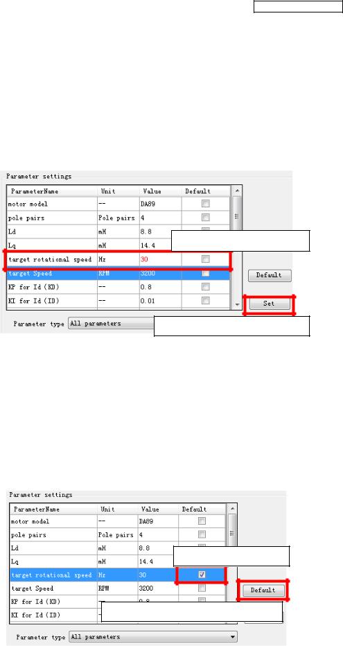
- How to operation of “Function/parameter settings window”
Open this window and you can see the default parameters values. If you want to change the value, after connecting to the board,
(1)Select the parameter
(2)Change the value directly (and the changed value becomes red)
(3)Push “set” button on the right.
(4)Be sent the value to MCU and set it.
Selected and changed value
Set button for parameter setting
If you want to change the default value, after connecting to the board,
(1)Select the parameter
(2)Check “default” button (and fill the checking symbol in the box)
(3)Push “default” button on the right.
(4)Be sent the default value to MCU and set it.
The default values are saved on the configuration files.
You can change the default value to load the configuration file.
Checked default box
Default button for parameter setting
15
AN706-00044-1v0-E
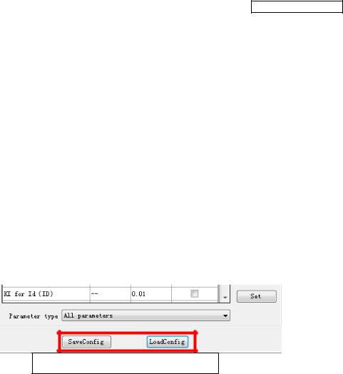
If you want to save the setting value, after connecting to the board and setting some parameters,
(1)Push “saveconfig” button under the window.
(2)Select the saving folder and name the .aip file
(3)Push save button and the configuration file is saved.
If you want to load the configuration file, after connecting to the board,
(1)Push “loadconfig” button under the window.
(2)Select the loaded .aip file
(3)Push open button and the configuration file is loaded.
Saveconfig and Loadconfig button
Some parameters can be set as an over-range value, but the firmware can modify as a maximum or minimum value automatically.
16
Loading...