


MHL2300AT
Table of contents
 Loading...
C141-E104-02EN
MHL2300AT, MHM2200AT,
MHM2150AT, MHM2100AT
DISK DRIVES
PRODUCT MANUAL

C141-E104-02EN
FOR SAFE OPERATION
Handling of This Manual
This manual contains important information for using this product. Read thoroughly before using
the product. Use this product only after thoroughly reading and understanding especially the
section “Important Alert Items” in this manual. Keep this manual handy, and keep it carefully.
FUJITSU makes every effort to prevent users and bystanders from being injured or from suffering
damage to their property. Use the product according to this manual.
IMPO R TANT NOTE TO USER S
READ THE ENTIRE MANUAL CAREFULLY BEFORE USING THI S PRODUCT.
INCORRECT USE OF THE PRO DUCT MAY RESULT IN INJURY OR DAMAGE TO
USERS, BYSTANDERS OR PROPERTY.
While FUJITSU has sought to ensure the accuracy of all information in this manual, FUJITSU
assumes no liability to any party for any damage caused by any error or omission contained in this
manual, its updates or supplements, whether such errors or omissions result from negligence,
accident, or any other cause. In addition, FUJITSU assumes no liability with respect to the
application or use of any product or system in accordance with the descriptions or instructions
contained herein; including any liability for incidental or consequential damages arising therefrom.
FUJITSU DISCLAIMS ALL WARRANTIES REGARDING THE INFORMATION CONTAINED
HEREIN, WHETHER EXPRESSED, IMPLIED, OR STATUTORY.
FUJITSU reserves the right to make changes to any products described herein without further
notice and without obligation.
The contents of this manual may be revised without prior notice.
The contents of this manual shall not be disclosed in any way or reproduced in any media without
the express written permission of Fujitsu Limited.
All Rights Reserved, Copyright FUJITSU LIMITED 2000

This page is intentionally left blank.
C141-E104-02EN
Revision History
(1/1)
Edition Date Revised section (*1)
(Added/Deleted/Altered)
Details
01 2000-02-15 — —
02 2000-09-20 -Table 1.1
- Table 1.2
- (16) SET MAX in Section
5.3.2
- Table 5.17
- Specification (Number of Sections for
MHL2300AT) was altered.
- Order No. was changed.
- SET MAX commands are added.
- Values of host termination for DIOR-,
DIOW- and DMACK- signals are
changed.
*1 Section(s) with asterisk (*) refer to the previous edition when those were deleted.

This page is intentionally left blank.

C141-E104-02EN i
Preface
This manual describes the MHL Series and MHM Series, 2.5-inch hard disk drives.
These drives have a built-in controller that is compatible with the ATA interface.
This manual describes the specifications and functions of the drives and explains in
detail how to incorporate the drives into user systems. This manual assumes that
the reader has a basic knowledge of hard disk drives and their implementations in
computer systems.
This manual consists of seven chapters and sections explaining the special
terminology and abbreviations used in this manual:
Overview of Manual
CHAPTER 1 Device Overview
This chapter gives an overview of the MHL Series and MHM Series and describes
their features.
CHAPTER 2 Device Configuration
This chapter describes the internal configurations of the MHL Series and MHM
Series and the configuration of the systems in which they operate.
CHAPTER 3 Installation Condit ions
This chapter describes the external dimensions, installation conditions, and switch
settings of the MHL Series and MHM Series.
CHAPTER 4 Theory of Device Operation
This chapter describes the operation theory of the MHL Series and MHM Series.
CHAPTER 5 Interface
This chapter describes the interface specifications of the MHL Series and MHM
Series.
CHAPTER 6 Operations
This chapter describes the operations of the MHL Series and MHM Series.
Terminology
This section explains the special terminology used in this manual.
Abbreviation
This section gives the meanings of the definitions used in this manual.
Preface
ii C141-E104-02EN
Conventions for Alert Messages
This manual uses the following conventions to show the alert messages. An alert
message consists of an alert signal and alert statements. The alert signal consists of
an alert symbol and a signal word or just a signal word.
The following are the alert signals and their meanings:
CAUTION
This indicates a hazardous situation could result in
minor or moderate personal injury if the user does
not perform the procedure correctly. This alert
signal also indicates that damages to the product or
other property may occur if the user does not perform
the procedure correctly.
IMPORTANT
This indicates information that could help the user
use the product more efficiently.
In the text, the alert signal is centered, followed below by the indented message. A
wider line space precedes and follows the alert message to show where the alert
message begins and ends. The following is an example:
(Example)
CAUTION
Data corruption: Avoid mounting the disk drive near strong
magnetic sources such as loud speakers. Ensure that the disk drive is
not affected by external magnetic fields.
The main alert messages in the text are also listed in the “Important Alert Items.”
Operating Environment
This product is designed to be used in offices or computer rooms.
For details regarding the operating environment of use, refer to the
(Cnnn-Xnnn) and the
(Cnnn-Xnnn).
Attention
Please forward any comments you may have regarding this manual.
To make this manual easier for users to understand, opinions from readers are
needed. Please write your opinions or requests on the Comment at the back of this
manual and forward it to the address described in the sheet.

Preface
C141-E104-02EN iii
Liability Exception
“Disk drive defects” refers to defects that involve adjustment, repair, or
replacement.
Fujitsu is not liable for any other disk drive defects, such as those caused by user
misoperation or mishandling, inappropriate operating environments, defects in the
power supply or cable, problems of the host system, or other causes outside the
disk drive.

This page is intentionally left blank.
C141-E104-02EN v
Important Alert Items
Important Alert Messages
The important alert messages in this manual are as follows:
CAUTION
A hazardous situation could result in minor or moderate personal
injury if the user does not perform the procedure correctly. Also,
damage to the predate or other property, may occur if the user does not
perform the procedure correctly.
Task Alert message Page
Normal Operation
Data corruption: Avoid mounting the disk near strong
magnetic sources such as loud speakers. Ensure that the disk
drive is not affected by external magnetic fields.
Damage: Do not press the cover of the disk drive. Pressing
it too hard, the cover and the spindle motor contact, which
may cause damage to the disk drive.
Static: When handling the device, disconnect the body
ground (500 kΩ or greater). Do not touch the printed circuit
board, but hold it by the edges.
3-8

This page is intentionally left blank.

C141-E104-02EN vii
Manual Organization
MHL2300AT, MHM2200AT,
MHM2150AT, MHM2100AT
DISK DRIVES
PRODUCT MANUAL
(C141-E104)
<This manual>
• Device Overview
• Device Configuration
• Installation Conditions
• Theory of Device Operation
• Interface
• Operations
MHL2300AT, MHM2200AT,
MHM2150AT, MHM2100AT
DISK DRIVES
MAINTENANCE MANUAL
(C141-F043)
• Maintenance and Diagnosis
• Removal and Replacement Procedure

This page is intentionally left blank.

C141-E104-02EN ix
Contents
CHAPTER 1 Device Overview ....................................................................... 1-1
1.1 Features 1-2
1.1.1 Functions and performance 1-2
1.1.2 Adaptability 1-2
1.1.3 Interface 1-3
1.2 Device Specifications 1-4
1.2.1 Specifications summary 1-4
1.2.2 Model and product number 1-5
1.3 Power Requirements 1-5
1.4 Environmental Specifications 1-7
1.5 Acoustic Noise 1-8
1.6 Shock and Vibration 1-8
1.7 Reliability 1-9
1.8 Error Rate 1-10
1.9 Media Defects 1-10
CHAPTER 2 Device Configuration................................................................ 2-1
2.1 Device Configuration 2-2
2.2 System Configuration 2-4
2.2.1 ATA interface 2-4
2.2.2 1 drive connection 2-4
2.2.3 2 drives connection 2-4

Contents
x C141-E104-02EN
CHAPTER 3 Installation Conditions..............................................................3-1
3.1 Dimensions 3-2
3.2 Mounting 3-4
3.3 Cable Connections 3-10
3.3.1 Device connector 3-10
3.3.2 Cable connector specifications 3-11
3.3.3 Device connection 3-11
3.3.4 Power supply connector (CN1) 3-12
3.4 Jumper Settings 3-12
3.4.1 Location of setting jumpers 3-12
3.4.2 Factory default setting 3-13
3.4.3 Master drive-slave drive setting 3-13
3.4.4 CSEL setting 3-14
CHAPTER 4 Theory of Device Operation......................................................4-1
4.1 Outline 4-2
4.2 Subassemblies 4-2
4.2.1 Disk 4-2
4.2.2 Head 4-2
4.2.3 Spindle 4-3
4.2.4 Actuator 4-3
4.2.5 Air filter 4-3
4.3 Circuit Configuration 4-4
4.4 Power-on Sequence 4-7
4.5 Self-calibration 4-8
4.5.1 Self-calibration contents 4-8
4.5.2 Execution timing of self-calibration 4-9
4.5.3 Command processing during self-calibration 4-10
4.6 Read/write Circuit 4-10
4.6.1 Read/write preamplifier (HDIC) 4-10

Contents
C141-E104-02EN xi
4.6.2 Write circuit 4-11
4.6.3 Read circuit 4-13
4.6.4 Digital PLL circuit 4-14
4.7 Servo Control 4-15
4.7.1 Servo control circuit 4-15
4.7.2 Data-surface servo format 4-18
4.7.3 Servo frame format 4-20
4.7.4 Actuator motor control 4-21
4.7.5 Spindle motor control 4-22
CHAPTER 5 Interface..................................................................................... 5-1
5.1 Physical Interface 5-2
5.1.1 Interface signals 5-2
5.1.2 Signal assignment on the connector 5-3
5.2 Logical Interface 5-6
5.2.1 I/O registers 5-7
5.2.2 Command block registers 5-8
5.2.3 Control block registers 5-13
5.3 Host Commands 5-13
5.3.1 Command code and parameters 5-14
5.3.2 Command descriptions 5-16
5.3.3 Error posting 5-83
5.4 Command Protocol 5-85
5.4.1 Data transferring commands from device to host 5-85
5.4.2 Data transferring commands from host to device 5-87
5.4.3 Commands without data transfer 5-89
5.4.4 Other commands 5-90
5.4.5 DMA data transfer commands 5-90
5.5 Ultra DMA Feature Set 5-92
5.5.1 Overview 5-92
5.5.2 Phases of operation 5-93

Contents
xii C141-E104-02EN
5.5.2.1 Ultra DMA burst initiation phase 5-93
5.5.2.2 Data transfer phase 5-94
5.5.2.3 Ultra DMA burst termination phase 5-94
5.5.3 Ultra DMA data in commands 5-95
5.5.3.1 Initiating an Ultra DMA data in burst 5-95
5.5.3.2 The data in transfer 5-96
5.5.3.3 Pausing an Ultra DMA data in burst 5-96
5.5.3.4 Terminating an Ultra DMA data in burst 5-97
5.5.4 Ultra DMA data out commands 5-100
5.5.4.1 Initiating an Ultra DMA data out burst 5-100
5.5.4.2 The data out transfer 5-100
5.5.4.3 Pausing an Ultra DMA data out burst 5-101
5.5.4.4 Terminating an Ultra DMA data out burst 5-102
5.5.5 Ultra DMA CRC rules 5-104
5.5.6 Series termination required for Ultra DMA 5-106
5.6 Timing 5-107
5.6.1 PIO data transfer 5-107
5.6.2 Multiword DMA data transfer 5-109
5.6.3 Transfer of Ultra DMA data 5-110
5.6.3.1 Starting of Ultra DMA data In Burst 5-110
5.6.3.2 Ultra DMA data burst timing requirements 5-111
5.6.3.3 Sustained Ultra DMA data in burst 5-113
5.6.3.4 Host pausing an Ultra DMA data in burst 5-114
5.6.3.5 Device terminating an Ultra DMA data in burst 5-115
5.6.3.6 Host terminating an Ultra DMA data in burst 5-116
5.6.3.7 Initiating an Ultra DMA data out burst 5-117
5.6.3.8 Sustained Ultra DMA data out burst 5-118
5.6.3.9 Device pausing an Ultra DMA data out burst 5-119
5.6.3.10 Host terminating an Ultra DMA data out burst 5-120
5.6.3.11 Device terminating an Ultra DMA data in burst 5-121
5.6.4 Power-on and reset 5-122
CHAPTER 6 Operations .................................................................................6-1
6.1 Device Response to the Reset 6-2

Contents
C141-E104-02EN xiii
6.1.1 Response to power-on 6-2
6.1.2 Response to hardware reset 6-4
6.1.3 Response to software reset 6-5
6.1.4 Response to diagnostic command 6-6
6.2 Address Translation 6-7
6.2.1 Default parameters 6-7
6.2.2 Logical address 6-8
6.3 Power Save 6-9
6.3.1 Power save mode 6-9
6.3.2 Power commands 6-11
6.4 Defect Management 6-11
6.4.1 Spare area 6-12
6.4.2 Alternating defective sectors 6-12
6.5 Read-Ahead Cache 6-14
6.5.1 Data buffer configuration 6-14
6.5.2 Caching operation 6-14
6.5.3 Usage of read segment 6-16
6.5.3.1 Mis-hit (no hit) 6-16
6.5.3.2 Sequential read 6-17
6.5.3.3 Full hit (hit all) 6-20
6.5.3.4 Partially hit 6-21
6.6 Write Cache 6-22
Glossary ..................................................................................................GL-1
Acronyms and Abbreviations......................................................................... AB-1

Contents
xiv C141-E104-02EN
Illustrations
Figures
Figure 1.1 Current fluctuation (Typ.) at +5V when power is turned on 1-7
Figure 2.1 Disk drive outerview (the MHL Series and MHM Series) 2-2
Figure 2.2 Configuration of disk media heads 2-3
Figure 2.3 1 drive system configuration 2-4
Figure 2.4 2 drives configuration 2-4
Figure 3.1 Dimensions (MHL/MHM series) 3-2
Figure 3.2 Orientation (Sample: MHL2300AT) 3-4
Figure 3.3 Mounting frame structure 3-5
Figure 3.4 Location of breather 3-6
Figure 3.5 Surface temperature measurement points
(Sample: MHL2300AT) 3 -7
Figure 3.6 Service area (Sample: MHL2300AT) 3-8
Figure 3.7 Handling cautions 3-9
Figure 3.8 Connector locations (Sample: MHL2300AT) 3-10
Figure 3.9 Cable connections 3-11
Figure 3.10 Power supply connector pins (CN1) 3-12
Figure 3.11 Jumper location 3-12
Figure 3.12 Factory default setting 3-13
Figure 3.13 Jumper setting of master or slave device 3-13
Figure 3.14 CSEL setting 3-14
Figure 3.15 Example (1) of Cable Select 3-14
Figure 3.16 Example (2) of Cable Select 3-15
Figure 4.1 Head structure 4-3
Figure 4.2 Power Supply Configuration 4-5
Figure 4.3 Circuit Configuration 4-6
Figure 4.4 Power-on operation sequence 4-8
Figure 4.5 Read/write circuit block diagram 4-12
Figure 4.6 Frequency characteristic of programmable filter 4-13
Figure 4.7 Block diagram of servo control circuit 4-15
Figure 4.8 Physical sector servo configuration on disk surface 4-19
Figure 4.9 Servo frame format 4-20
Figure 5.1 Interface signals 5-2
Figure 5.2 Execution example of READ MULTIPLE command 5-20

Contents
C141-E104-02EN xv
Figure 5.3 Read Sector(s) command protocol 5-86
Figure 5.4 Protocol for command abort 5-87
Figure 5.5 WRITE SECTOR(S) command protocol 5-88
Figure 5.6 Protocol for the command execution without data transfer 5-90
Figure 5.7 Normal DMA data transfer 5-91
Figure 5.8 An example of generation of parallel CRC 5-105
Figure 5.9 Ultra DMA termination with pull-up or pull-down 5-106
Figure 5.10 Data transfer timing 5-108
Figure 5.11 Multiword DMA data transfer timing (mode 2) 5-109
Figure 5.12 Starting of Ultra DMA data In Burst transfer 5-110
Figure 5.13 Sustained Ultra DMA data in burst 5-113
Figure 5.14 Host pausing an Ultra DMA data in burst 5-114
Figure 5.15 Device terminating an Ultra DMA data in burst 5-115
Figure 5.16 Host terminating an Ultra DMA data in burst 5-116
Figure 5.17 Initiating an Ultra DMA data out burst 5-117
Figure 5.18 Sustained Ultra DMA data out burst 5-118
Figure 5.19 Device pausing an Ultra DMA data out burst 5-119
Figure 5.20 Host terminating an Ultra DMA data out burst 5-120
Figure 5.21 Device terminating an Ultra DMA data out burst 5-121
Figure 5.22 Power on Reset Timing 5-122
Figure 6.1 Response to power-on 6-3
Figure 6.2 Response to hardware reset 6-4
Figure 6.3 Response to software reset 6-5
Figure 6.4 Response to diagnostic command 6-6
Figure 6.5 Address translation (example in CHS mode) 6-8
Figure 6.6 Address translation (example in LBA mode) 6-9
Figure 6.7 Sector slip processing 6-12
Figure 6.8 Alternate cylinder assignment 6-13
Figure 6.9 Data buffer configuration 6-14
Tables
Table 1.1 Specifications 1-4
Table 1.2 Model names and product numbers 1-5
Table 1.3 Current and power dissipation 1-6
Table 1.4 Environmental specifications 1-7
Table 1.5 Acoustic noise specification 1-8
Table 1.6 Shock and vibration specification 1-8
Table 3.1 Surface temperature measurement points and standard values 3-7
Table 3.2 Cable connector specifications 3-11

Contents
xvi C141-E104-02EN
Table 4.1 Self-calibration execution timechart 4-10
Table 4.2 Write precompensation algorithm 4-11
Table 5.1 Signal assignment on the interface connector 5-3
Table 5.2 I/O registers 5-7
Table 5.3 Command code and parameters 5-14
Table 5.4 Information to be read by IDENTIFY DEVICE command 5-32
Table 5.5 Features register values and settable modes 5-41
Table 5.6 Diagnostic code 5-52
Table 5.7 Features Register values (subcommands) and functions 5-64
Table 5.8 Format of device attribute value data 5-68
Table 5.9 Format of insurance failure threshold value data 5-68
Table 5.10 SMART error log data format 5-72
Table 5.11 SMART self test log data format 5-74
Table 5.12 Contents of security password 5-76
Table 5.13 Contents of SECURITY SET PASSWORD data 5-80
Table 5.14 Relationship between combination of Identifier and Security level,
and operation of the lock function 5-80
Table 5.15 Command code and parameters 5-83
Table 5.16 Parallel generation equation of CRC polynomial 5-105
Table 5.17 Recommended series termination for Ultra DMA 5-106
Table 5.18 Ultra DMA data burst timing requirements 5-111
Table 6.1 Default parameters 6-7

C141-E104-02EN 1-1
CHAPTER 1 Device Overview
1.1 Features
1.2 Device Specifications
1.3 Power Requirements
1.4 Environmental Specifications
1.5 Acoustic Noise
1.6 Shock and Vibration
1.7 Reliability
1.8 Error Rate
1.9 Media Defects
Overview and features are described in this chapter, and specifications and power
requirement are described.
The MHL Series and MHM Series are 2.5-inch hard disk drives with built-in disk
controllers. These disk drives use the AT-bus hard disk interface protocol and are
compact and reliable.

Device Overview
1-2 C141-E104-02EN
1.1 Features
1.1.1 Functions and performance
The following features of the MHL Series and MHM Series are described.
(1) Compact
The MHL2300AT has 3 built-in disks (the diameter is 65mm[2.5inch]), and its
height is 12.5 mm (0.492 inch). The MHM2200AT, MHM2150AT and
MHM2100AT have 1 disk or 2 disks of 65 mm (2.5 inches) diameter, and its
height is 9.5 mm (0.374 inch).
(2) Large capacity
The disk drive can record up to 10 GB (formatted) on one disk using the 16/17
MTR recording method and 15 recording zone technology. The MHL Series and
MHM Series have a formatted capacity of 30 GB (MHL2300AT), 20 GB
(MHM2200AT), 15 GB (MHM2150AT) and 10 GB (MHM2100AT) respectively.
(3) High-speed Transfer rate
The disk drives (the MHL Series and MHM Series) have an internal data rate up
to 28.7 MB/s. The disk drive supports an external data rate up to 66.6 MB/s (U-
DMA mode 4).
(4) Average positioning time
Use of a rotary voice coil motor in the head positioning mechanism greatly
increases the positioning speed. The average positioning time is 12 ms (at read).
1.1.2 Adaptability
(1) Power save mode
The power save mode feature for idle operation, stand by and sleep modes makes
The disk drives (the MHL Series and MHM Series) ideal for applications where
power consumption is a factor.
(2) Wide temperature range
The disk drives (the MHL Series and MHM Series) can be used over a wide
temperature range (5°C to 55°C).
(3) Low noise and vibration
In Ready status, the noise of the disk drives (the MHL Series and MHM Series) is
only about 30 dBA (measured at 1 m apart from the drive under the idle mode).

1.1 Features
C141-E104-02EN 1-3
1.1.3 Interface
(1) Connection to interface
With the built-in ATA interface controller, the disk drives (the MHL Series and
MHM Series) can be connected to an ATA interface of a personal computer.
(2) 2 MB data buffer
The disk drives (the MHL Series and MHM Series) uses a 2 MB data buffer to
transfer data between the host and the disk media.
In combination with the read-ahead cache system described in item (3) and the
write cache described in item (7), the buffer contributes to efficient I/O
processing.
(3) Read-ahead cache system
After the execution of a disk read command, the disk drive automatically reads the
subsequent data block and writes it to the data buffer (read ahead operation). This
cache system enables fast data access. The next disk read command would
normally cause another disk access. But, if the read ahead data corresponds to the
data requested by the next read command, the data in the buffer can be transferred
instead.
(4) Master/slave
The disk drives (the MHL Series and MHM Series) can be connected to ATA
interface as daisy chain configuration. Drive 0 is a master device, drive 1 is a
slave device.
(5) Error correction and retry by ECC
If a recoverable error occurs, the disk drives (the MHL Series and MHM Series)
themselves attempt error recovery. The ECC has improved buffer error correction
for correctable data errors.
(6) Self-diagnosis
The disk drives (the MHL Series and MHM Series) have a diagnostic function to
check operation of the controller and disk drives. Executing the diagnostic
command invokes self-diagnosis.
(7) Write cache
When the disk drives (the MHL Series and MHM Series) receive a write
command, the disk drives post the command completion at completion of
transferring data to the data buffer completion of writing to the disk media. This
feature reduces the access time at writing.
Device Overview
1-4 C141-E104-02EN
1.2 Device Specifications
1.2.1 Specifications summary
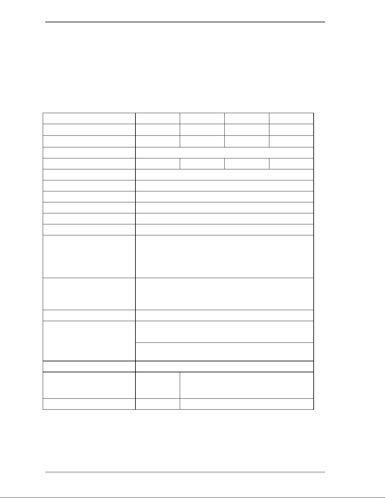
Table 1.1 shows the specifications of the disk drives (MHL Series and MHM Series).
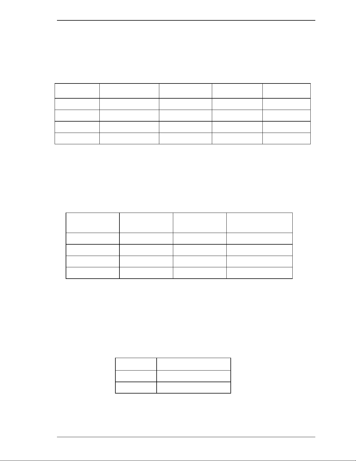
Table 1.1 Specifications ( 1/ 2)
MHL2300AT MHM2200AT MHM2150AT MHM2100AT
Format Capacity (*1) 30 GB 20 GB
15 GB 10 GB
Number of Heads 6 4
32
Number of Cylinders (User) 19,904
Number of Sectors (User) 58,605,120 39,070,080 29,498,112 19,640,880
Bytes per Sector 512
Recording Method 16/17 MTR
Track Density 32,300 TPI (1271 track/mm)
Bit Density 499.7 Kbpi (19.67 k bit/m m )
Rotational Speed 4,200 rpm ± 1%
Average Latency 7.14 ms
Positioning time (read and seek)
• Minimum (Track to Track)
• Average
• Maximum (Full)
1.5 ms (typ.)
Read: 12 ms (typ.)
22 ms (typ.)
Start/Stop time
• Start (0 rpm to Drive Read)
• Stop (at Power Down)
Typ.: 5 sec
Typ.: 5 sec
Interface ATA-5 (Max. Cable length: 0.46 m)
Data Transfer Rate
• To/From Media 16.4 to 28.7 MB/s
• To/From Host 66.6 MB/s Max.
(U-DMA mode 4)
Data Buffer Size 2 MB
Physical Dimensions
(Height × Width × Depth)
12.5 mm ×
100.0 mm ×
70.0 mm
9.5 mm × 100.0 mm ×70.0 mm
Weight 134 g 98 g
*1: Capacity under the LBA mode.
1.3 Power Requirements
C141-E104-02EN 1-5
Under the CHS mode (normal BIOS specification), formatted capacity,
number of cylinders, number of heads, and number of sectors are as
follows.
Table 1.1 Specifications ( 2/ 2)
Model Capacity No. of Cylinder No. of Heads No. of Sectors
MHL2300AT 8.45 GB 16,383 16 63
MHM2200AT 8.45 GB 16,383 16 63
MHM2150AT 8.45 GB 16,383 16 63
MHM2100AT 8.45 GB 16,383 16 63
1.2.2 Model and product number
Table 1.2 lists the model names and product numbers of the MHL Series and
MHM Series.
Table 1.2 Model names and product numbers
Model Name Capacity
(user area)
Mounting screw Order No.
MHL2300AT 30 GB M3, depth 3 CA05428-B061
MHM2200AT 20 GB M3, depth 3 CA05429-B041
MHM2150AT 15 GB M3, depth 3 CA05429-B031
MHM2100AT 10 GB M3, depth 3 CA05429-B021
1.3 Power Requirements
(1) Input Voltage
• + 5 V ± 5 %
(2) Ripple
+5 V
Maximum 100 mV (peak to peak)
Frequency DC to 1 MHz
Device Overview
1-6 C141-E104-02EN
(3) Current Requirements and Power Dissipation
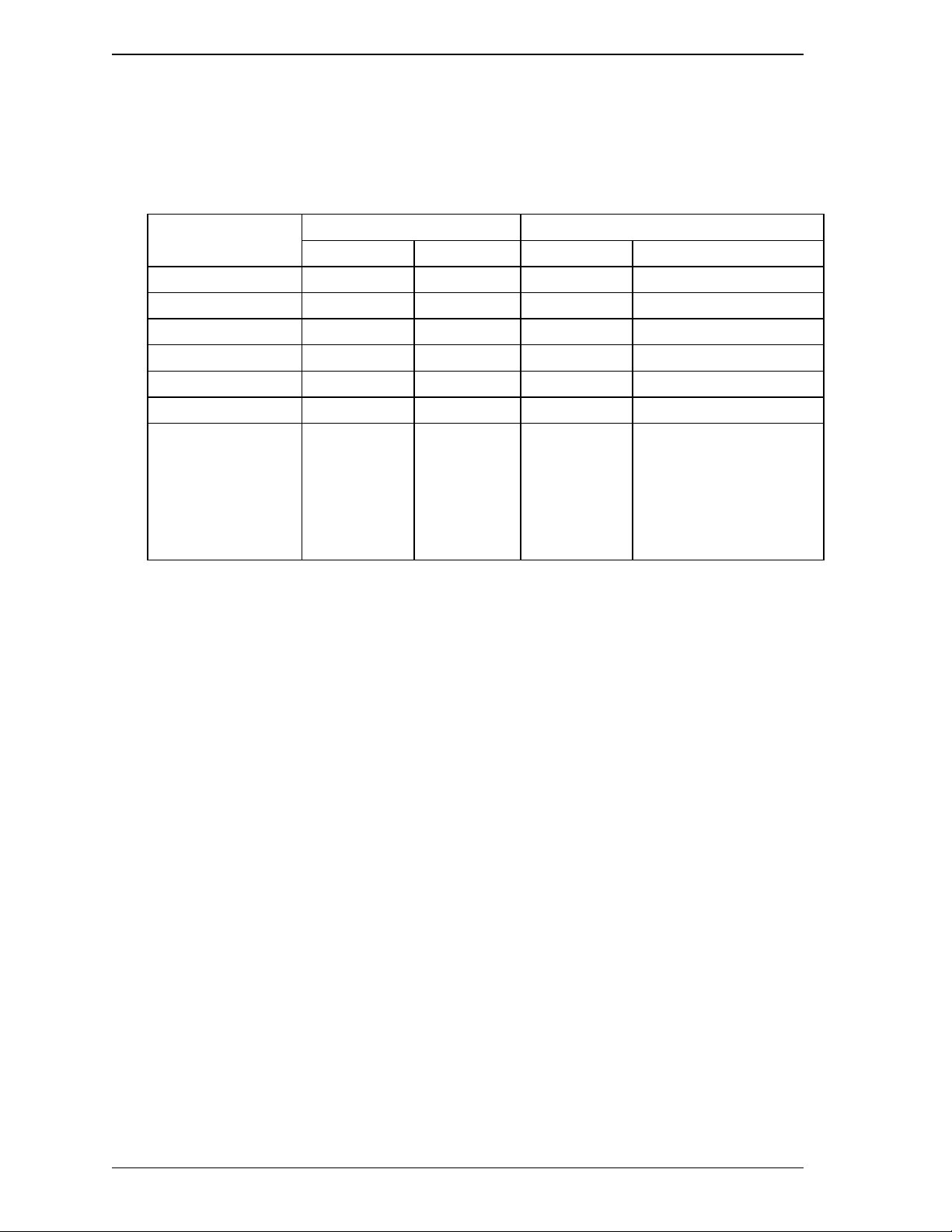
Table 1.3 lists the current and power dissipation.
Table 1.3 Current and power di ssi pat i on
Typical RMS Current Typical Power (*3)
MHL Series MHM Series MHL Series MHM Series
Spin up (*1) 0.9 A 0.9 A 4.5 W 4.5 W
Idle 190 mA 160 mA 0.95 W 0.8 W
R/W (on track) (*2) 520 mA 500 mA 2.6 W 2.5 W
Seek (*5) 490 mA 460 mA 2.45 W 2.3 W
Standby 50 mA 50 mA 0.25 W 0.25 W
Sleep 20 mA 20 mA 0.1 W 0.1 W
Energy
Efficiency (*4)
— — 0.032 W/GB
(rank E)
0.040 W/GB
(rank E / MHM2200AT)
0.040 W/GB
(rank E / MHM2150AT)
0.080 W/GB
(rank D / MHM2100AT)
*1 Current at starting spindle motor.
*2 At 30% disk accessing.
*3 Power requirements reflect nominal values for +5V power.
*4 Energy efficiency based on the Law concerning the Rational Use of Energy
indicates the value obtained by dividing power consumption by the storage
capacity. (Japan only)
*5 The seek average current is specified based on three operations per 100
msec.
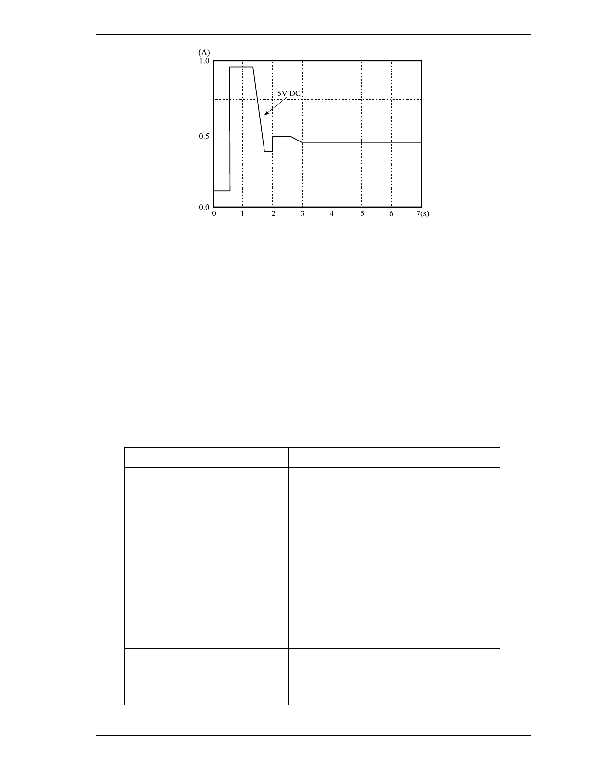
(4) Current fluctuation (Typ.) at +5V when power is turned on
1.4 Environmental Specifications
C141-E104-02EN 1-7
Figure 1.1 Current fluctuation (Typ.) at +5V when power is turned on
(5) Power on/off sequence
The voltage detector circuits (the MHL Series and MHM Series) monitor +5 V.
The circuits do not allow a write signal if either voltage is abnormal. These
prevent data from being destroyed and eliminates the need to be concerned with
the power on/off sequence.
1.4 Environmental Specifications
Table 1.4 lists the environmental specifications.
Table 1.4 Environmental specifications
Item Specification
Temperature
• Operating
• Non-operating
• Thermal Gradient
5°C to 55°C (ambient)
5°C to 60°C (disk enclosure surface)
–40°C to 65°C
20°C/h or less
Humidity
• Operating
• Non-operating
• Maximum Wet Bulb
8% to 90% RH (Non-condensing)
5% to 95% RH (Non-condensing)
29°C (Operating)
40°C (Non-operating)
Altitude (relative to sea level)
• Operating
• Non-operating
–300 to 3,000 m
–300 to 12,000 m
Device Overview
1-8 C141-E104-02EN
1.5 Acoustic Noise
Table 1.5 lists the acoustic noise specification.
Table 1.5 Acoustic noise specification
Item Specification
Sound Pressure
• Idle mode (DRIVE READY) 30 dBA typical at 1 m
Note:
Measure the noise from the cover top surface.
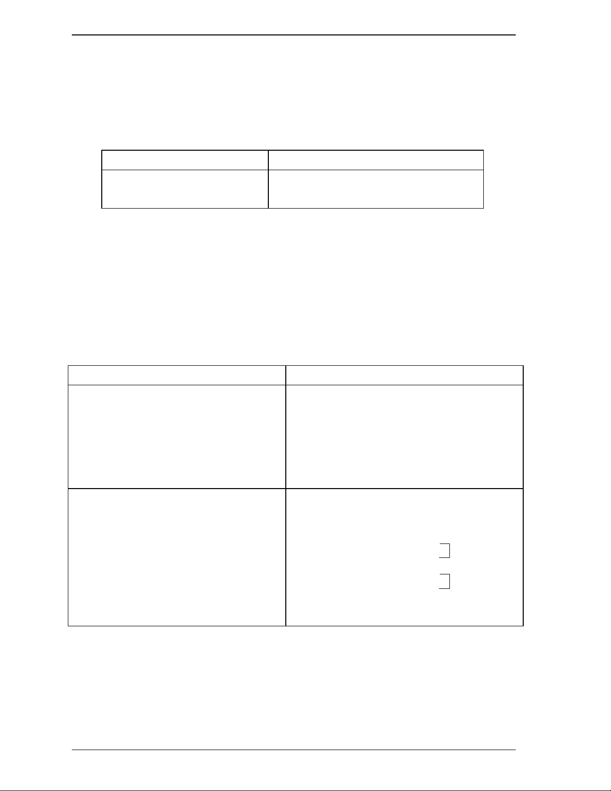
1.6 Shock and Vibration
Table 1.6 lists the shock and vibration specification.
Table 1.6 Shock and vibration specificati on
Item Specification
Vibration (swept sine, one octave per minute)
• Operating
• Non-operating
5 to 500 Hz, 1.0G 0-peak (MHL series)
5 to 400 Hz, 1.0G 0-peak (MHM series)
(without non-recovered errors) (9.8 m/s
2
0-peak)
5 to 500 Hz, 5G 0-peak (MHL series)
5 to 400 Hz, 5G 0-peak (MHM series)
(no damage) (49 m/s
2
0-peak)
Shock (half-sine pulse)
• Operating
• Non-operating
175G 0-peak (1,715 m/s
2
0-peak)
2 ms duration (without non-recovered errors)
600G 0-peak (5,880 m/s
2
0-peak)
2 ms duration (no damage)
700G 0-peak (6,860 m/s
2
0-peak)
2 ms duration (no damage)
120G 0-peak (1,176 m/s
2
0-peak)
11 ms duration (no damage)
MHM series
MHL series
1.7 Reliability
C141-E104-02EN 1-9
1.7 Reliability
(1) Mean time between failures (MTBF)
Conditions of 300,000 h Power-on time 250H/month or less 3000H/years
or less
Operating time 20% or less of power-on time
CSS operations 50/day or less
Total 50,000 or less
Power on/off 1/day or more needed.
Environment 5 to 55°C/8 to 90%
But humidity bulb temperature
29°C or less
MTBF is defined as follows:
Total operation time in all fields
MTBF= (H)
number of device failure in all fields (*1)
*1 “Disk drive defects” refers to defects that involve repair, readjustment, or
replacement. Disk drive defects do not include failures caused by external
factors, such as damage caused by handling, inappropriate operating
environments, defects in the power supply host system, or interface cable.
(2) Mean time to repair (MTTR)
The mean time to repair (MTTR) is 30 minutes or less, if repaired by a specialist
maintenance staff member.
(3) Service life
In situations where management and handling are correct, the disk drive requires
no overhaul for five years when the DE surface temperature is less than 48°C.
When the DE surface temperature exceeds 48°C, the disk drives requires no
overhaul for five years or 20,000 hours of operation, whichever occurs first.
Refer to item (3) in Subsection 3.2 for the measurement point of the DE surface
temperature. Also the operating conditions except the environment temperature
are based on the MTBF conditions.
(4) Data assurance in the event of power failure
Except for the data block being written to, the data on the disk media is assured in
the event of any power supply abnormalities. This does not include power supply
abnormalities during disk media initialization (formatting) or processing of
defects (alternative block assignment).
Loading...