


AN07-00180-3E
FR Family FR60 Lite 32-BIT MICROCONTROLLER MB91F267N
bits pot red CAN-Motor board
User’s Manual

AN07-00180-3E
Revision History
Date |
Revision |
|
|
August 01, 2008 |
Revision 1.0: Initial release |
|
|
September 17, 2008 |
Revision 1.1 |
|
On p.12, type corrected. Correct: NL565050T-103J, Incorrect: L565050T-103J |
|
|
October 22, 2008 |
Revision 1.2 |
|
On p.13, a download web page is changed. |
|
On p.20, "1.1.1 Downloading the software" is added. |
|
On p.25, p.30, p.36 and p.43, |
|
Description is corrected about the extracting file. |
|
The file path is added. |
|
|
|
(left blank) |
|
|
|
|
- 2 -

AN07-00180-3E
Note
-The contents of this document are subject to change without notice. Customers are advised to consult with FUJITSU sales representatives before ordering.
-The information, such as descriptions of function and application circuit examples, in this document are presented solely for the purpose of reference to show examples of operations and uses of Fujitsu semiconductor device; Fujitsu does not warrant proper operation of the device with respect to use based on such information. When you develop equipment incorporating the device based on such information, you must assume any responsibility arising out of such use of the information. Fujitsu assumes no liability for any damages whatsoever arising out of the use of the information.
-Any information in this document, including descriptions of function and schematic diagrams, shall not be construed as license of the use or exercise of any intellectual property right, such as patent right or copyright, or any other right of Fujitsu or any third party or does Fujitsu warrant non-infringement of any third-party’s intellectual property right or other right by using such information. Fujitsu assumes no
liability for any infringement of the intellectual property rights or other rights of third parties which
would result from the use of information contained herein.
-The products described in this document are designed, developed and manufactured as contemplated for general use, including without limitation, ordinary industrial use, general office use, personal use, and household use, but are not designed, developed and manufactured as contemplated (1) for use accompanying fatal risks or dangers that, unless extremely high safety is secured, could have a serious effect to the public, and could lead directly to death, personal injury, severe physical damage or other loss (i.e., nuclear reaction control in nuclear facility, aircraft flight control, air traffic control, mass transport control, medical life support system, missile launch control in weapon system), or (2) for use requiring extremely high reliability (i.e., submersible repeater and artificial satellite).
Please note that Fujitsu will not be liable against you and/or any third party for any claims or damages arising in connection with above-mentioned uses of the products.
-Any semiconductor devices have an inherent chance of failure. You must protect against injury, fire, damage or loss from such failures by incorporating safety design measures into your facility and equipment such as redundancy, fire protection, and prevention of over-current levels and other abnormal operating conditions.
-If any products described in this document represent goods or technologies subject to certain restrictions on export under the Foreign Exchange and Foreign Trade Law of Japan, the prior authorization by Japanese government will be required for export of those products from Japan.
-The company names and brand names herein are the trademarks or registered trademarks of their respective owners.
Copyright© 2008 FUJITSU MICROELECTRONICS LIMITED all rights reserved
-3 -

AN07-00180-3E
Table of Contents
Revision History ......................................................................................................................... |
2 |
|
Note .......................................................................................................................................... |
|
3 |
Introduction .............................................................................................................................. |
10 |
|
Contact .................................................................................................................................... |
|
11 |
Suppliers of the parts/materials.................................................................................................... |
12 |
|
1 Setting up the starter kit ...................................................................................................... |
13 |
|
1.1 |
Setting up the PC ..................................................................................................... |
19 |
1.1.1 |
Downloading the software ........................................................................................ |
20 |
1.1.2 |
Installing a USB driver ............................................................................................ |
20 |
1.1.3 Installing the integrated development environment SOFTUNE (bits pot dedicated version) ............ |
25 |
|
1.1.4 |
Installing PC Writer (bits pot red dedicated version)..................................................... |
30 |
1.1.5 Configuring the evaluation board and connecting it to the PC ........................................ |
33 |
|
2 Running the program .......................................................................................................... |
35 |
|
2.1 |
Executing in single chip mode................................................................................... |
36 |
2.1.1 |
Building a project.................................................................................................... |
36 |
2.1.2 Writing the program into the microcontroller............................................................... |
38 |
|
2.2 |
Debugging by using Monitor Debugger ..................................................................... |
43 |
2.2.1 |
Writing Monitor Debugger into the microcontroller ..................................................... |
43 |
2.2.2 Activating SOFTUNE and configuring the debug settings............................................. |
48 |
|
2.2.3 Writing the program into the microcontroller............................................................... |
55 |
|
2.2.4 |
Loading the target file .............................................................................................. |
57 |
2.2.5 |
Running the debugger .............................................................................................. |
58 |
2.2.6 |
Notes on Monitor Debugger...................................................................................... |
59 |
3 Operation of the sample program.......................................................................................... |
60 |
|
3.1 |
bits pot red single-unit operation ............................................................................... |
61 |
3.2 |
CAN communication operation (CAN communication operation with the bits pot white) .......... |
63 |
4 Try to rotate the BLDC motor .............................................................................................. |
65 |
|
4.1 |
What is the BLDC motor? ......................................................................................... |
65 |
4.2 |
How does the BLDC motor rotate? ........................................................................... |
66 |
4.3 |
BLDC motor rotation control by the microcontroller ................................................... |
68 |
4.4 |
Understanding and running the program for the BLDC motor operation..................... |
75 |
4.5 |
Handling controls of the BLDC motor ........................................................................ |
78 |
5 Try to use CAN communication ........................................................................................... |
82 |
|
5.1 |
What is CAN?........................................................................................................... |
82 |
|
- 4 - |
|

AN07-00180-3E
5.2 |
CAN specifications ................................................................................................... |
84 |
|
5.2.1 |
CAN frame configurations ................................................................................. |
84 |
|
5.2.2 |
|
Arbitration ............................................................................................................. |
88 |
5.2.3 |
|
Error management................................................................................................... |
90 |
5.3 |
CAN communication by using the microcontroller ..................................................... |
92 |
|
5.4 |
Understanding and running the program for CAN communication ............................. |
95 |
|
5.4.1 |
|
CAN communication configuration ........................................................................... |
95 |
5.4.2 |
|
Sample program sequence ........................................................................................ |
99 |
6 Appendix ........................................................................................................................ |
104 |
||
6.1 |
Sample program folder/file configuration ................................................................. |
104 |
|
- 5 -

|
AN07-00180-3E |
List of Figures |
|
Figure 1-1 External board view......................................................................................... |
14 |
Figure 1-2 System connection diagram ............................................................................ |
16 |
Figure 1-3 Downloading the USB driver ................................................................................ |
20 |
Figure 1-4 Installing FT232R USB UART ............................................................................. |
21 |
Figure 1-5 Selecting the search locations................................................................................ |
22 |
Figure 1-6 Completing the USB Serial Converter installation.................................................... |
22 |
Figure 1-7 Installing USB Serial Port .................................................................................... |
23 |
Figure 1-8 Selecting the search locations................................................................................ |
23 |
Figure 1-9 Completing the USB Serial Port installation............................................................ |
24 |
Figure 1-10 SOFTUNE setup confirmation ............................................................................ |
25 |
Figure 1-11 Starting SOFTUNE setup ................................................................................... |
25 |
Figure 1-12 Caution on SOFTUNE setup ............................................................................... |
26 |
Figure 1-13 SOFTUNE setup/License agreement .................................................................... |
26 |
Figure 1-14 SOFTUNE setup/Version information .................................................................. |
27 |
Figure 1-15 SOFTUNE setup/Selecting the destination of installation ........................................ |
27 |
Figure 1-16 SOFTUNE setup/Selecting the components........................................................... |
28 |
Figure 1-17 SOFTUNE setup/Confirming the installation settings ............................................. |
28 |
Figure 1-18 SOFTUNE setup/Completion.............................................................................. |
29 |
Figure 1-19 PC Writer/Installation dialog............................................................................... |
30 |
Figure 1-20 PC Writer/Setup type ......................................................................................... |
31 |
Figure 1-21 PC Writer/Ready to install .................................................................................. |
31 |
Figure 1-22 Completing the PC Writer installation .................................................................. |
32 |
Figure 1-23 MODE selection................................................................................................ |
33 |
Figure 1-24 Connection between the PC and the board............................................................. |
34 |
Figure 2-1 Opening a workspace........................................................................................... |
36 |
Figure 2-2 Selecting a workspace.......................................................................................... |
37 |
Figure 2-3 Building a project................................................................................................ |
37 |
Figure 2-4 Completing the build ........................................................................................... |
38 |
Figure 2-5 Opening the file to write....................................................................................... |
38 |
Figure 2-6 Selecting the file to write...................................................................................... |
39 |
Figure 2-7 Select the COM port to be used for the writing ........................................................ |
40 |
Figure 2-8 Checking the COM port ....................................................................................... |
41 |
Figure 2-9 Writing the program ............................................................................................ |
42 |
Figure 2-10 Completing the program writing .......................................................................... |
42 |
- 6 - |
|

AN07-00180-3E
Figure 2-11 Opening the file to write ..................................................................................... |
43 |
Figure 2-12 Selecting the file to write.................................................................................... |
44 |
Figure 2-13 Select the COM port to be used for the writing ...................................................... |
45 |
Figure 2-14 Checking the COM port ..................................................................................... |
46 |
Figure 2-15 Writing the program........................................................................................... |
47 |
Figure 2-16 Completing the program writing .......................................................................... |
47 |
Figure 2-17 Opening a workspace ......................................................................................... |
48 |
Figure 2-18 Selecting a workspace ........................................................................................ |
49 |
Figure 2-19 Building a project .............................................................................................. |
49 |
Figure 2-20 Completing the build ......................................................................................... |
50 |
Figure 2-21 Changing the debug settings ......................................................................... |
50 |
Figure 2-22 Starting the debug setting wizard ......................................................................... |
51 |
Figure 2-23 Selecting the debugger type ................................................................................ |
51 |
Figure 2-24 Selecting the device type .................................................................................... |
52 |
Figure 2-25 Specifying a batch file........................................................................................ |
52 |
Figure 2-26 Configuring the target file settings ....................................................................... |
53 |
Figure 2-27 Setting setup file selection .................................................................................. |
53 |
Figure 2-28 Completing the setup wizard ............................................................................... |
54 |
Figure 2-29 Start debugging ................................................................................................. |
54 |
Figure 2-30 Showing the commands window.......................................................................... |
55 |
Figure 2-31 Inputting commands .......................................................................................... |
56 |
Figure 2-32 Completing the program writing .......................................................................... |
56 |
Figure 2-33 Loading the target file ........................................................................................ |
57 |
Figure 2-34 Setting break points ........................................................................................... |
58 |
Figure 2-35 Running the program ......................................................................................... |
58 |
Figure 2-36 Stopping the program......................................................................................... |
59 |
Figure 3-1 Single-unit operation/Controls and mechanicals ...................................................... |
61 |
Figure 3-2 CAN communication operation/Controls and mechanicals ........................................ |
63 |
Figure 4-1 DC motor/BLDC motor configuration examples...................................................... |
65 |
Figure 4-2 Names of the respective elements .......................................................................... |
66 |
Figure 4-3 120° conduction method time chart.................................................................. |
67 |
Figure 4-4 Motor driver circuit........................................................................................... |
68 |
Figure 4-5 Timer control registers ......................................................................................... |
69 |
Figure 4-6 Output compare registers...................................................................................... |
71 |
Figure 4-7 Operation of the free-run timer......................................................................... |
73 |
Figure 4-8 U-High output to output comparisons ............................................................... |
74 |
- 7 - |
|

AN07-00180-3E
Figure 4-9 Motor operation flowchart .................................................................................... |
75 |
Figure 4-10 Operation mode settings ..................................................................................... |
76 |
Figure 4-11 Main function ................................................................................................... |
76 |
Figure 4-12 SW2 interrupt ................................................................................................... |
77 |
Figure 4-13 Free-run timer interrupt ...................................................................................... |
77 |
Figure 4-14 Motor controls flowchart................................................................................. |
78 |
Figure 4-15 Rotation speed control........................................................................................ |
79 |
Figure 4-16 Brake control .................................................................................................... |
80 |
Figure 4-17 Rotation direction control ................................................................................... |
81 |
Figure 5-1 Example of on-board CAN application................................................................... |
82 |
Figure 5-2 CAN bus signal levels.......................................................................................... |
83 |
Figure 5-3 CAN frame configurations ................................................................................... |
85 |
Figure 5-4 Operation of the arbitration................................................................................... |
88 |
Figure 5-5 Example of arbitration among nodes................................................................ |
89 |
Figure 5-6 CAN status transition........................................................................................... |
91 |
Figure 5-7 CAN circuit........................................................................................................ |
92 |
Figure 5-8 Entire CAN communication control register............................................................ |
93 |
Figure 5-9 CAN communication flowchart......................................................................... |
99 |
Figure 5-10 Operation mode settings ................................................................................... |
100 |
Figure 5-11 Main function ................................................................................................. |
100 |
Figure 5-12 CAN timer interrupt control .............................................................................. |
101 |
Figure 5-13 Motor rotation information transmit ................................................................... |
102 |
Figure 5-14 Temperature sensor information transmit ............................................................ |
102 |
Figure 5-15 CAN receive processing ................................................................................... |
103 |
- 8 -

AN07-00180-3E
List of Tables |
|
|
Table 1-1 Component list.................................................................................................... |
13 |
|
Table 1-2 Description of the respective board parts.................................................................. |
15 |
|
Table 1-3 MB91F267N pin assignment.................................................................................. |
17 |
|
Table 3-1 Single-unit operation/Descriptions of the controls and mechanicals ............................. |
62 |
|
Table 3-2 CAN communication operation/Descriptions of the controls and mechanicals ............... |
64 |
|
Table 4-1 Microcontroller pin/Motor driver circuit connections................................................ |
69 |
|
Table 4-2 Functions employed by the motor driving macro....................................................... |
69 |
|
Table 4-3 Description of the timer control registers and setting values........................................ |
70 |
|
Table 4-4 Description of the output compare registers and setting values .................................... |
72 |
|
Table 4-5 Correspondence between the output compare values and the switchings.......... |
73 |
|
Table 5-1 |
Description of the error types ................................................................................. |
90 |
Table 5-2 |
Description of the entire CAN communication control registers and setting values......... |
94 |
Table 5-3 |
CAN communication conditions of the sample program............................................. |
95 |
Table 5-4 CAN message IDs in the sample program ................................................................ |
96 |
|
Table 6-1 |
Sample program folder/file configuration............................................................... |
104 |
- 9 -

AN07-00180-3E
Introduction
Thank you very much for purchasing the bits pot red (referred to as this starter kit or the starter kit hereafter).
This starter kit is a beginner’s kit intended for those who wish to start learning microcontrollers and on-board network processors. The kit is designed so that the beginners who ask “What is a microcontroller?”, “How does it work?” and “How does it control a network?” can easily learn what it is.
The kit includes flash microcontroller development tools, so if you have slight understanding about the C language, you can rewrite a program to let the microcontroller perform in various ways. Even if you do not know of programming, you may be able to enjoy learning a microcontroller with a study-aid book about the C language.
This starter kit can also serve as an introductory training tool for electronic circuit practice or future embedded software development in a class of a college or high school of technology or training for freshman engineers of a manufacturer.
- 10 -
AN07-00180-3E
Contact
For inquiries about this starter kit, contact the following address.
Zip code: 105-8420 2-5-3 Nishi-Shinbashi, Minatoku, Tokyo
E-mail: pd-bitspot@tsuzuki-densan.co.jp
bits pot URL: http://www.tsuzuki-densan.co.jp/bitspot/
- 11 -

AN07-00180-3E
Suppliers of the parts/materials
Capacitors |
22 pF |
: GCM1552C1H220JZ02 |
|
0.1 μF |
: GCM188R11E104KA42 |
|
1 μF |
: GCM21BR11E105KA42 |
|
10 μF |
: GCM32ER71E106KA42 |
Ceramic oscillator |
|
: CSTCR4M00G15C |
NTC Thermistors |
: NTCG164BH103JT1 |
Ferrite Beads |
: MPZ2012S300AT |
Common Mode Filters |
: ZJYS81R5-2P24T-G01 |
Inductors |
: NL565050T-103J |
- 12 -
AN07-00180-3E
1 Setting up the starter kit
Before using this starter kit, be sure to check the components listed in Table 1-1 are fully supplied.
Before connecting the bits pot red CAN-Motor board (referred to as the board hereafter), you need to install software in your PC. You can download the software required for the starter kit from the following web site.
bits pot URL http://www.tsuzuki-densan.co.jp/bitspot/
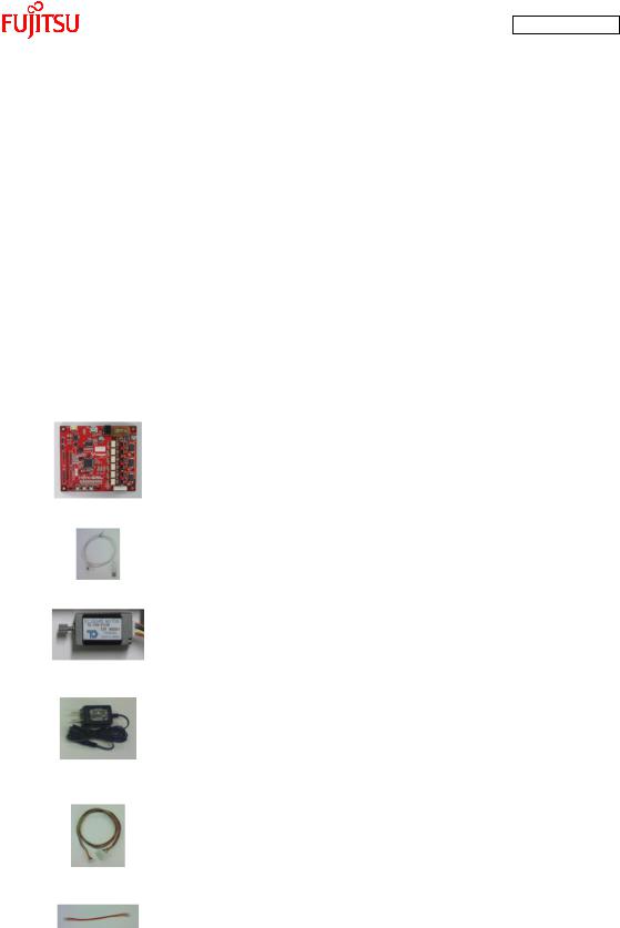
Table 1-1 Component list
No. |
Article |
Qty. |
Specifications |
Remarks |
|
|
|
|
|
1 |
bits pot red |
1 |
Microcontroller made by Fujitsu |
See Figure 1-1 |
|
CAN motor board |
|
FR Family FR60 Lite, MB91F267N |
|
|
|
|
mounted |
|
|
|
|
|
|
2 |
USB cable |
1 |
USB (A to miniB) |
Accessory |
|
|
|
|
|
3 |
BLDC Motor |
1 |
Tsukasa Electronic TG-22D-F539, |
Accessory |
|
|
|
12 V |
|
|
|
|
|
|
4 |
AC adapter |
1 |
12 V, 1 A |
Accessory |
|
|
|
|
Be sure to use the adapter |
|
|
|
|
included in the kit |
|
|
|
|
|
5 |
Motor cable |
1 |
8-pin cable |
Accessory |
|
|
|
|
|
6 |
CAN cable |
1 |
3-pin cable |
Accessory |
|
|
|
|
|
7 |
PC |
1 |
On which Windows XP normally |
Prepare the PC by yourself. |
|
|
|
runs and USB2.0 ports are |
|
|
|
|
supported |
|
|
|
|
|
|
- 13 -

AN07-00180-3E
|
|
|
|
|
(5) USB to UART converter |
|
|
|
|
|
|
|
|
(4) CAN connector |
|
(6) USB connector |
|
|
|
|
|
|
|
|
|
|
|
|
|
(3) CAN transceiver |
|
|
|
|
(9) DC jack |
|
|
|
(17) Jumper pin |
||
|
|
|
|
||
(15) Fuse
(7) Motor driver circuit
(18) Extension power
(19) Extension GND 
(16)Extension pins
(1)Target device
(2)Target device oscillator
|
|
(8) Motor connector |
(10) Mode SW |
(12) Test SW |
(14) Temperature sensor |
|
(13) LED lamps |
|
(11) Reset SW |
||
|
||
|
|
|
Figure 1-1 External board view |
||
- 14 -

AN07-00180-3E
“Table 1-2 Description of the respective board parts” provides descriptions of the respective board parts.
Table 1-2 Description of the respective board parts
No. |
Name |
Function |
Description |
|
|
|
|
|
|
|
|
||
(1) |
Target device |
MB91F267N |
Main microcontroller (MB91F267N). |
|
||
|
|
|
|
|
||
|
|
|
Ceralock made by Murata Manufacturing |
|
||
(2) |
Target device oscillator |
CSTCR4M00G15C |
|
|
|
|
|
|
|
Oscillator for the main microcontroller. |
|
||
|
|
|
|
|
||
(3) |
CAN transceiver |
MAX3058ASA+ |
Transceiver IC for CAN communication. |
|
||
|
|
|
|
|
||
|
|
|
Connector for CAN communication. |
|
||
(4) |
CAN connector |
3-pin connector |
Connect this connector to the CAN connector on the |
|||
|
|
|
bits pot white. |
|
|
|
|
|
|
|
|
||
(5) |
USB to UART converter |
FT232RL |
IC for conversion between UART and USB. |
|
||
|
|
|
|
|
|
|
|
|
|
USB connector |
for connection |
with the |
PC to |
(6) |
USB connector |
miniB |
|
|
|
|
|
|
|
write/debug a program. |
|
|
|
|
|
|
|
|||
|
|
3-phase motor driver |
Driver circuit for 3-phase motor operation by the main |
|||
(7) |
Motor driver circuit |
|
|
|
|
|
|
|
circuit |
microcontroller. |
|
|
|
|
|
|
|
|
|
|
|
|
|
Connector for |
connection with |
the 3-phase |
motor |
(8) |
Motor connector |
8 pins |
|
|
|
|
|
|
|
included in the kit. |
|
|
|
|
|
|
|
|
||
(9) |
DC jack |
- |
Power connector for the operation of the motor. |
|
||
|
|
|
|
|||
(10) |
Mode SW |
Slide switch |
Switch for selection of operation mode of the board. |
|||
|
|
|
|
|
|
|
(11) |
Reset SW |
Push switch |
Switch to reset the board. |
|
|
|
|
|
|
|
|
||
|
|
Push switch x 2 |
Connected to the general-purpose I/O port. |
|
||
(12) |
Test switches |
|
|
|
|
|
|
|
Slide switch x 1 |
The sample program uses this switch for motor rotation. |
|||
|
|
|
|
|
|
|
|
|
LED (green) x 6 |
|
|
|
|
(13) |
LED lamps |
|
General-purpose LED lamps. |
|
|
|
|
|
LED (red) x 3 |
|
|
|
|
|
|
|
|
|
|
|
|
|
|
NTC thermistor made by TDK |
|
|
|
(14) |
Temperature sensor |
NTCG164BH103 |
|
|
|
|
|
|
|
Temperature sensor connected to the A/D converter. |
|||
|
|
|
|
|
|
|
(15) |
Fuse |
0217001P |
Fuse for the 12-V power supply. |
|
|
|
|
|
|
|
|
||
|
|
|
Extension pins of the main microcontroller. |
|
||
(16) |
Extension pins |
- |
|
|
|
|
|
|
|
For details, see the circuit diagram. |
|
|
|
|
|
|
|
|
||
|
|
|
Jumper pins for USB-UART conversion setting. |
|
||
|
|
|
UART communication handshake setting. |
|
||
(17) |
Jumper pins (JP1, JP2) |
- |
1-2: Handshake by software. |
|
|
|
|
|
|
2-3: Handshake by hardware. |
|
|
|
|
|
|
The default setting is 2-3 (common to JP1/JP2). |
|
||
|
|
|
|
|
|
|
- 15 -
AN07-00180-3E
(18) |
Extension power (5V) |
- |
Extension 5-V power terminal. |
|
|
|
|
(19) |
Extension GND |
- |
Extension GND terminal. |
|
|
|
|
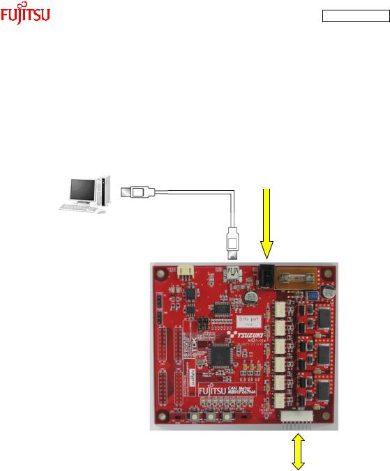
“Figure 1-2 System connection diagram” shows the connection of the system.
* Prepare the PC by yourself.
Use the USB cable included in the kit for the connection. (The power is supplied from the USB bus power.)
AC adapter (accessory)
Use the AC adapter included in the kit for the connection. (The motor power is supplied from the AC adapter.)
BLDC motor (accessory)
Figure 1-2 System connection diagram
Connect the PC with the board by using the USB cable included in the kit.
The power is supplied to the board from the USB bus power.
Directly connect the USB port to that on the PC. Do not make the connection via a USB hub.
- 16 -

AN07-00180-3E
“Table 1-3 MB91F267N pin assignment” shows the pin assignment of the main microcontroller
MB91F267N.
Table 1-3 MB91F267N pin assignment
Pin No. |
Description |
Connected to: |
Remarks |
1 |
AVss |
GND |
|
|
|
|
|
2 |
ACC |
GND |
|
|
|
|
|
3 |
AN0/P50 |
Motor driver circuit |
|
|
|
|
|
4 |
AN1/P51 |
Motor driver circuit |
|
|
|
|
|
5 |
AN2/P52 |
Motor driver circuit |
|
|
|
|
|
6 |
AN3/P53 |
- |
|
|
|
|
|
7 |
AN4/P54 |
LED6 |
L output = On |
|
|
|
|
8 |
AN5/P55 |
LED7 |
L output = On |
|
|
|
|
9 |
AN6/P56 |
LED8 |
L output = On |
|
|
|
|
10 |
AN7/P57 |
LED9 |
L output = On |
|
|
|
|
11 |
AN8/P44 |
LED10 |
L output = On |
|
|
|
|
12 |
AN9/P45 |
LED11 |
L output = On |
|
|
|
|
13 |
AN10/P46 |
Thermistor |
|
|
|
|
|
14 |
NMI |
5 V |
|
|
|
|
|
15 |
C |
GND |
|
|
|
|
|
16 |
Vss |
GND |
|
|
|
|
|
17 |
Vcc |
5 V |
|
|
|
|
|
18 |
INT4/PPG1/P00 |
LED12 |
|
|
|
|
|
19 |
PPG2/P01 |
LED13 |
|
|
|
|
|
20 |
INT5/PPG3/P02 |
LED14 |
|
|
|
|
|
21 |
TIN0/P03 |
- |
|
|
|
|
|
22 |
TIN1/P04 |
- |
|
|
|
|
|
23 |
TIN2/P05 |
- |
|
|
|
|
|
24 |
TOT1/P06 |
- |
|
|
|
|
|
25 |
TOT2/P07 |
- |
|
|
|
|
|
26 |
SOT0/P10 |
USB-UART conversion |
|
|
|
|
|
27 |
SIN0/P11 |
USB-UART conversion |
|
|
|
|
|
28 |
SCK0/P12 |
- |
|
|
|
|
|
29 |
SOT1/P13 |
- |
|
|
|
|
|
30 |
SIN1/P14 |
- |
|
|
|
|
|
31 |
SCK1/P15 |
- |
|
|
|
|
|
- 17 -

AN07-00180-3E
32 |
INT6/PPG5/RX0/P16 |
CAN TRANSCEIVER |
|
||
|
|
|
|
|
|
33 |
PPG6/TX0/P17 |
CAN TRANSCEIVER |
|
||
|
|
|
|
|
|
34 |
ADTG1/IC2/P20 |
Motor driver circuit |
Hall W-phase |
||
|
|
|
|
|
|
35 |
ADTG2/IC3/P21 |
- |
|
||
|
|
|
|
|
|
36 |
PWI0/P22 |
- |
|
||
|
|
|
|
|
|
37 |
DTTI/P23 |
- |
|
||
|
|
|
|
|
|
38 |
CKI/P24 |
- |
|
||
|
|
|
|
|
|
39 |
IC0/P25 |
Motor driver circuit |
Hall U-phase |
||
|
|
|
|
|
|
40 |
IC1/P26 |
Motor driver circuit |
Hall V-phase |
||
|
|
|
|
|
|
41 |
P27 |
SW5 |
|
||
|
|
|
|
|
|
42 |
PPG0/PG1 |
- |
|
||
|
|
|
|
|
|
43 |
MD2 |
SW4 |
|
||
|
|
|
|
|
|
44 |
MD1 |
GND |
|
||
|
|
|
|
|
|
45 |
MD0 |
GND |
|
||
|
|
|
|
|
|
46 |
X0 |
Q1 |
4-MHz oscillator |
||
|
|
|
|
|
|
47 |
X1 |
Q1 |
4-MHz oscillator |
||
|
|
|
|
|
|
48 |
Vss |
GND |
|
||
|
|
|
|
|
|
49 |
PPG4/P37 |
- |
|
||
|
|
|
|
|
|
50 |
INT7/PPG7/P36 |
- |
|
||
|
|
|
|
|
|
|
|
|
|
|
|
51 |
INIT |
RESET(SW1) |
|
||
|
|
|
|
||
|
|
|
|
|
|
52 |
RTO5/P35 |
Motor driver circuit |
W-phase Low |
||
|
|
|
|
|
|
53 |
RTO4/P34 |
Motor driver circuit |
W-phase High |
||
|
|
|
|
|
|
54 |
RTO3/P33 |
Motor driver circuit |
V-phase Low |
||
|
|
|
|
|
|
55 |
RTO2/P32 |
Motor driver circuit |
V-phase High |
||
|
|
|
|
|
|
56 |
RTO1/P31 |
Motor driver circuit |
U-phase Low |
||
|
|
|
|
|
|
57 |
RTO0/P30 |
Motor driver circuit |
U-phase High |
||
|
|
|
|
|
|
58 |
INT0/P40 |
SW2 |
SW pressed = L |
||
|
|
|
|
|
|
59 |
INT1/P41 |
SW3 |
SW pressed = L |
||
|
|
|
|
|
|
60 |
INT2/P42 |
USB-UART conversion |
|
||
|
|
|
|
|
|
61 |
INT3/P43 |
USB-UART conversion |
|
||
|
|
|
|
|
|
62 |
AVRH1 |
5 V |
|
||
|
|
|
|
|
|
63 |
AVRH2 |
5 V |
|
||
|
|
|
|
|
|
64 |
AVcc |
5 V |
|
||
|
|
|
|
|
|
- 18 -

AN07-00180-3E
1.1Setting up the PC
Install the software required to operate this starter kit into the PC.
To set up the PC, take the following procedures.
(1)Downloading the software
(2)Installing a USB driver
(3)Installing the integrated development environment SOFTUNE (function-limited version)
(4)Installing PC Writer FUJITSU FLASH MCU Programmer (bits pot red dedicated version)
(5)Configuring the evaluation board and connecting it to the PC
- 19 -
AN07-00180-3E
1.1.1Downloading the software
Download the file from the following web site, and extract the file. bits pot URL http://www.tsuzuki-densan.co.jp/bitspot/
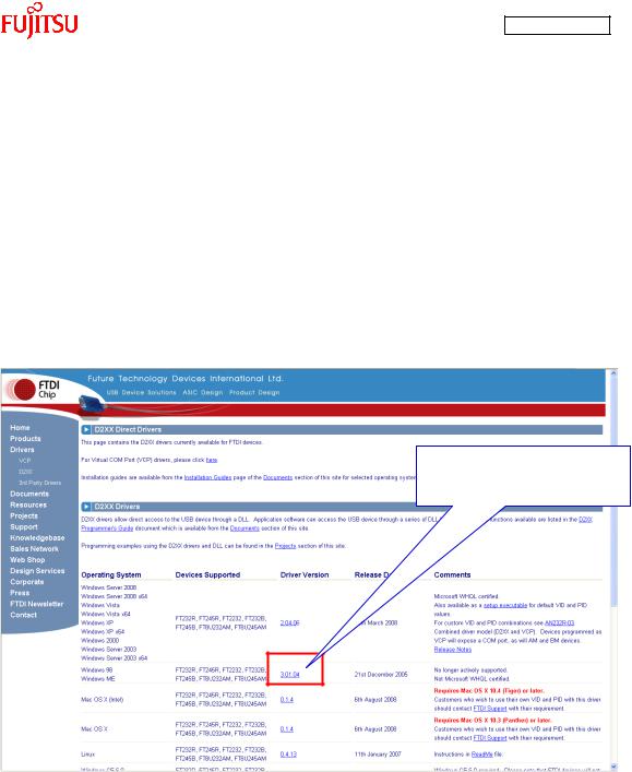
1.1.2Installing a USB driver
Install a USB driver.
From the FTDI web page shown below, download the Windows driver as directed in “Figure 1-3 Downloading the USB driver”.
http://www.ftdichip.com/Drivers/D2XX.htm
Click on the driver version to download.
Figure 1-3 Downloading the USB driver
- 20 -
AN07-00180-3E
After downloading the driver, decompress it, and then connect the board to the PC by using the USB cable included in the kit. As shown in “Figure 1-4 Installing FT232R USB UART”, the dialog for “FT232R USB UART” installation is displayed; select “Install from a list or specific location”, and then click the “Next” button.
Figure 1-4 Installing FT232R USB UART
- 21 -
AN07-00180-3E
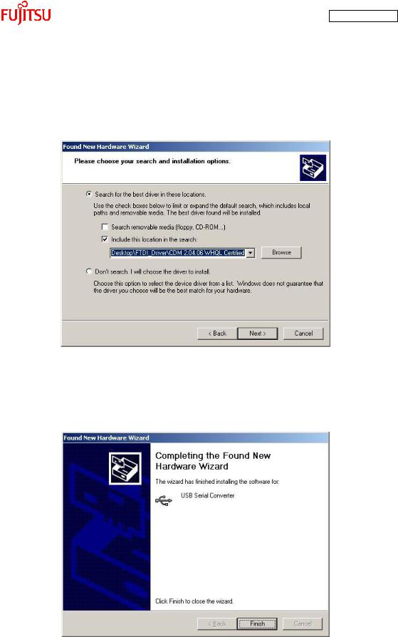
As shown in “Figure 1-5 Selecting the search locations”, to search for the installation file, check “Search for the best driver in these locations” and “Include this location in the search” only, select the location at which the driver was decompressed, and then click the “Next” button; installation of the driver starts.
Figure 1-5 Selecting the search locations
When the driver installation ends, the dialog shown in “Figure 1-6 Completing the USB Serial Converter ” is displayed; click the “Finish” button.
Figure 1-6 Completing the USB Serial Converter installation
- 22 -

AN07-00180-3E
After that, as shown in “Figure 1-7 Installing USB Serial Port”, installation of “USB Serial Port” is indicated; select “Install from a list or specific location” and then click the “Next” button.
Figure 1-7 Installing USB Serial Port
As shown in “Figure 1-8 Selecting the search locations”, to search for the installation file, check “Search for the best driver in these locations” and “Include this location in the search” only, select the location at which the driver was decompressed, and then click the “Next” button; installation of the driver starts.
Figure 1-8 Selecting the search locations
- 23 -
AN07-00180-3E
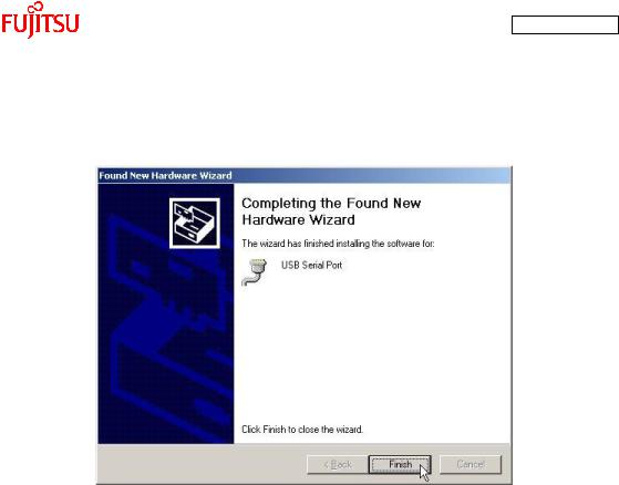
When the driver installation ends, the dialog shown in “Figure 1-9 Completing the USB Serial Port
installation” is displayed; Click the “Finish” button.
Figure 1-9 Completing the USB Serial Port installation
- 24 -
AN07-00180-3E
1.1.3Installing the integrated development environment SOFTUNE (bits pot dedicated
version)
Note
If SOFTUNE V6 of the product version has been installed, first uninstall it, and then install the bits
pot dedicated version.
Start installing the integrated development environment SOFTUNE. Extract the following file from the inside of the folder extracted by “1.1.1 Downloading the software”.
¥softwares¥softune¥REV600010-BV.zip
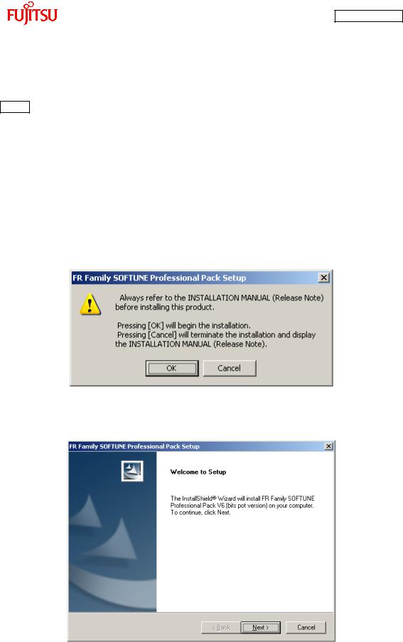
Double-click “Setup.exe” in the decompressed folder; the dialog shown in “Figure 1-10 SOFTUNE setup confirmation” is displayed. Click the “OK” button.
Figure 1-10 SOFTUNE setup confirmation
The setup wizard shown in “Figure 1-11 Starting SOFTUNE setup” is displayed; click the “Next” button.
Figure 1-11 Starting SOFTUNE setup
- 25 -
AN07-00180-3E
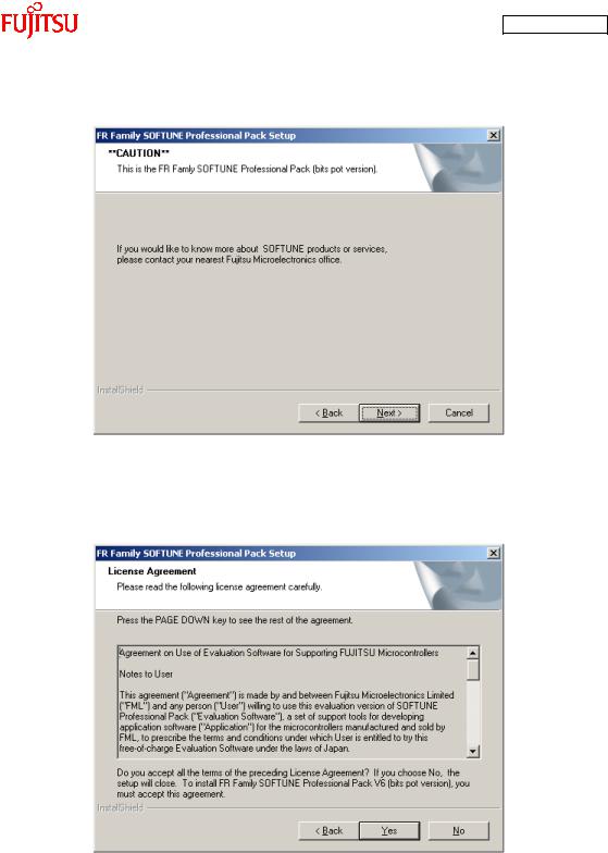
The dialog shown in “Figure 1-12 Caution on SOFTUNE setup” is displayed; click the “Next” button.
Figure 1-12 Caution on SOFTUNE setup
The dialog shown in “Figure 1-13 SOFTUNE setup/License agreement” appears; read through the agreements and then click “Yes” button.
Figure 1-13 SOFTUNE setup/License agreement
- 26 -
AN07-00180-3E
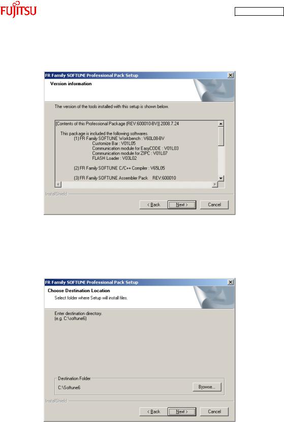
The version information is displayed as shown in “Figure 1-14 SOFTUNE setup/Version ”; click the “Next” button.
Figure 1-14 SOFTUNE setup/Version information
The dialog about the destination of installation shown in “Figure 1-15 SOFTUNE setup/Selecting the destination of installation” appears; select the default folder or desired folder and then click the “Next” button.
Figure 1-15 SOFTUNE setup/Selecting the destination of installation
- 27 -
AN07-00180-3E
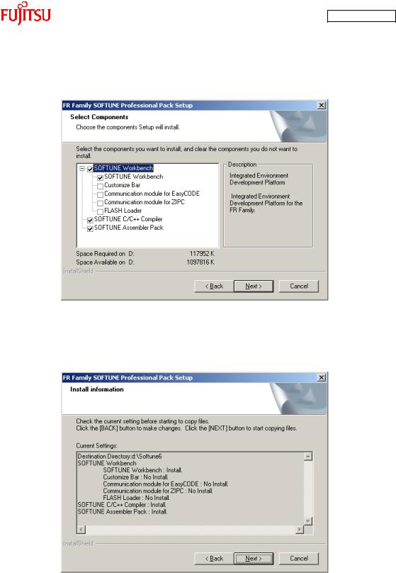
The dialog for component selection is displayed as shown in “Figure 1-16 SOFTUNE setup/Selecting the components”; keep the default settings and then click the “Next” button.
Figure 1-16 SOFTUNE setup/Selecting the components
As shown in “Figure 1-17 SOFTUNE setup/Confirming the installation settings”, the dialog for confirmation of the installation settings is displayed. Click the “Next” button; installation begins.
Figure 1-17 SOFTUNE setup/Confirming the installation settings
- 28 -
AN07-00180-3E
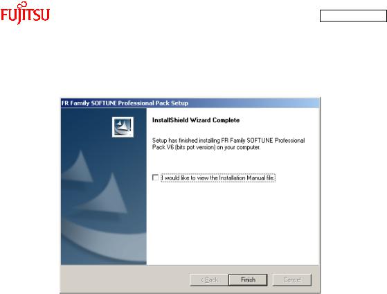
The dialog shown in “Figure 1-18 SOFTUNE setup/Completion” appears to tell the completion of
installation; click the “Finish” button.
Figure 1-18 SOFTUNE setup/Completion
- 29 -

AN07-00180-3E
1.1.4Installing PC Writer (bits pot red dedicated version)
Start installing PC Writer. Confirm the following file from the inside of the folder extracted by “1.1.1 Downloading the software”.
¥softwares¥pc writer¥MB91F267NA_setup.exe
Double-click “MB91F267NA_setup.exe”; the dialog shown in “Figure 1-19 PC Writer/Installation dialog” appears and installation starts; click the “Next” button.
Figure 1-19 PC Writer/Installation dialog
- 30 -
 Loading...