


HDC, CFHDC, SCFHDC,
FPHDC, LHDC, Y/KSCF/C/HC, BK1814
(High Efficiency Common Cabinet
Decathlon Fryers)
(HD) Decathlon Efficiency High
Fryers Gas Series
Manual Parts & Service
Dean, a member of the Commercial Food Equipment Service Association, recommends using CFESA Certified Technicians.
|
24-Hour Service Hotline |
01/2018 |
|
PRINTED IN THE UNITED STATES |
*8196314* |
||
1-800-551-8633 |
|||
|
|
OF AMERICA |
EMAIL: fryservice@welbilt.com |
|
Please read all sections of this manual and retain for future reference.
This product has been certified as commercial cooking equipment and MUST be installed by
professional personnel as specified. Installation, maintenance and repairs should be performed by your FRYMASTER AUTHORIZED SERVICER.
 DANGER
Do not store or use gasoline or other flammable vapors and liquids in the vicinity of this or any other cooking appliance.
 DANGER
Instructions explaining procedures to be followed MUST be posted in a prominent location in
the event the operator detects a gas leak. This information can be obtained from the local gas company or gas supplier.
 WARNING
Improper installation, adjustment, alteration, service or maintenance can cause property damage, injury or death. Read the installation, operating and maintenance instructions thoroughly before installing or servicing this equipment.
 DANGER
Safe and satisfactory operation of your equipment depends on proper installation. Installation MUST conform with local codes, or in absence of local codes, with the National Fuel Gas Code,
ANSI Z223.1; The Natural Gas Installation Code, CAN/CGA-B149.1; The Propane Installation Code, CAN/CGA-B149.2; or The latest edition of the National Electric Code, N.F.P.A. 70.
NOTICE
If, during the warranty period, the customer uses a part for this Frymaster Dean Food Service equipment other than an unmodified new or recycled part purchased directly from Frymaster and Dean, or any of its authorized service centers, and/or the part being used is modified from its original configuration, this warranty will be void. Further, Frymaster Dean and its affiliates will not be liable for any claims, damages or expenses incurred by the customer which arise directly or indirectly, in whole or in part, due to the installation of any modified part and/or part received from an unauthorized service center.
 DANGER
The crumb tray in fryers equipped with a filter system must be emptied into a fireproof container at the end of frying operations each day. Some food particles can spontaneously combust if left soaking in certain shortening material. Additional information can be obtained in the filtration manual included with the system.
 DANGER
The front ledge of the fryer is not a step. Do not stand on the fryer. Serious injury can result from slips or contact with the hot oil.
 WARNING
Drawings and photos used in this manual are intended to illustrate operational, cleaning and technical procedures and may not conform to on-site management operational procedures.
 WARNING
No structural material on the fryer should be altered or removed to accommodate placement of the fryer under a hood. Questions? Call the Frymaster and Dean Service Hotline at 1-800-551- 8633.
This equipment is to be installed in compliance with the basic plumbing code of The Building Officials and Code Administrators International, Inc. (BOCA) and the Food Service Sanitation Manual of the Food and Drug Administration.
COMPUTERS
FCC
This device complies with Part 15 of the FCC rules. Operation is subject to the following two conditions: 1) This device may not cause harmful interference, and 2) This device must accept any interference received, including interference that may cause undesired operation. While this device is a verified Class A device, it has been shown to meet the Class B limits.
CANADA
This digital apparatus does not exceed the Class A or B limits for radio noise emissions as set out by the ICES-003 standard of the Canadian Department of Communications.
Cet appareil numerique n’emet pas de bruits radioelectriques depassany les limites de classe A et B prescrites dans la norme NMB-003 edictee par le Ministre des Communcations du Canada.
 DANGER
THIS PRODUCT CONTAINS CHEMICALS KNOWN TO THE STATE OF CALIFORNIA TO CAUSE
CANCER AND/OR BIRTH DEFECTS OR OTHER REPRODUCTIVE HARM. Operation, installation, and servicing of this product could expose you to airborne particles of glasswool or ceramic fibers, crystalline silica, and/or carbon monoxide. Inhalation of airborne
particles of glasswool or ceramic fibers is known to the State of California to cause cancer. Inhalation of carbon monoxide is known to the State of California to cause birth defects or other reproductive harm.
 WARNING
Do not bang fry baskets or other utensils on the fryer’s joiner strip. The strip is present to seal the joint between the fry vessels. Banging fry baskets on the strip to dislodge shortening will distort the strip, adversely affecting its fit. It is designed for a tight fit and should only be removed for cleaning.

High Efficiency Decathlon (HD) Series Gas Fryers
Service and Parts Manual
TABLE OF CONTENTS
1.SERVICE PROCEDURES
1.1 |
Functional Description............................................................................................ |
1-1 |
1.2 |
Accessing Fryers for Service................................................................................... |
1-7 |
1.3 |
Cleaning the Gas Valve Vent Tube (if applicable)................................................ |
1-9 |
1.4 |
Adjusting Burner Manifold Gas Pressure............................................................. |
1-9 |
1.5 |
Adjusting the Pilot Flame...................................................................................... |
1-10 |
1.6 |
Calibrating the Thermatron Controller and Backup Thermostat.................... |
1-10 |
1.7 |
Replacing Fryer Components............................................................................... |
1-11 |
1.8 |
Troubleshooting and Problem Isolation.............................................................. |
1-29 |
1.9 |
Troubleshooting Guides........................................................................................ |
1-37 |
1.10 |
Wiring Diagrams.................................................................................................... |
1-38 |
1.11 |
Probe Resistance Charts........................................................................................ |
1-52 |
2.PARTS LIST
2.1 |
Decathlon(HDC) Primary Components................................................................ |
2-1 |
2.2 |
Orifices.................................................................................................................... |
2-16 |
2.3 |
Additional Optional Components and Controllers............................................. |
2-17 |
2.4 |
Drain Components................................................................................................. |
2-19 |
2.5 |
Oil Return System.................................................................................................. |
2-23 |
2.6 |
Additional Oil Return Components..................................................................... |
2-25 |
2.7 |
Oil Disposal (Popeye's and Church’s).................................................................. |
2-27 |
2.8 |
Oil Return Wand.................................................................................................... |
2-28 |
2.9 |
Over-the-Top Oil Return System......................................................................... |
2-29 |
2.10 |
Filtration Components........................................................................................... |
2-30 |
2.11 |
Basket Lift Components........................................................................................ |
2-38 |
2.12 |
Accessories.............................................................................................................. |
2-40 |
2.13 |
Fasteners (Screws, Nuts, Bolts)............................................................................. |
2-41 |
2.14 |
Flexlines................................................................................................................... |
2-42 |
APPENDIX: Pre-Common Cabinet HD65 Parts List.................................................. |
2-43 |
|
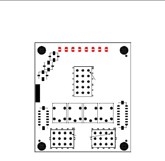
FINDING YOUR WAY AROUND THE DEAN HIGH EFFICIENCY DECATHLON
Basket Hanger |
Flue Cap |
Frypot |
Top Cap
|
Electronic |
|
Operating |
Controller |
Thermostat |
Drain Tubes |
Oil Return Handle |
|
Burners Drain Valve Handle (Red) |
Filter Unit |
Gas Valve |
Oil Return Handle (Yellow) |
|
|
Drain Flush Handle (Blue) |
|
|
Note: The appearance of your fryer may differ slightly from that shown depending upon configuration and date of manufacture.
HIGH EFFICIENCY DECATHLON SERIES GAS FRYERS
CHAPTER 1: SERVICE PROCEDURES
1.1 Functional Description
High Efficiency Decathlon (HD) Series gas fryers contain a welded stainless steel frypot heated by gas flames diffused evenly through tubes built into the frypot.
Flames originate from orifices in a burner manifold positioned beneath cast-steel burners. The burners are positioned in the tube openings at the front of the frypot. The diameter of the orifices differs for natural and LP gas as indicated in the accompanying table.
GAS INFORMATION (Altitudes of 2000 feet or less)
|
INPUT |
GAS |
ORIFICE |
ORIFICE |
|
EQUIPMENT |
||
MODEL |
|
PRESSURE |
||||||
MM |
QTY |
|||||||
(BTU) |
TYPE |
PART NO. |
|
|
||||
|
(INCH) |
|
MBAR |
INCH W.C. |
||||
|
|
|
|
|
|
|
|
|
HD50G |
95 |
NAT |
2.26(#43) |
810-2938 |
4 |
10 |
4 |
|
LP |
1.40(#54) |
810-2939 |
4 |
27.5 |
10 |
|||
|
|
|||||||
|
|
|
|
|
|
|
|
|
HD60/63/65G |
125 |
NAT |
2.26(#43) |
810-2938 |
5 |
10 |
4 |
|
LP |
1.40(#54) |
810-2939 |
5 |
27.5 |
10 |
|||
|
|
|||||||
|
|
|
|
|
|
|
|
|
An electromechanical gas valve regulates gas flow to the manifold. HD Series gas fryers are equipped with either a 24V valve system. Unit configurations include either a pilot ignition system or an electronic ignition system.
1-1

HIGH EFFICIENCY DECATHLON SERIES GAS FRYERS
CHAPTER 1: SERVICE PROCEDURES
1.1 Functional Description (cont.)
Pilot System Configuration
The pilot system is comprised of the pilot orifice, pilot hood, and a thermopile (some systems incorporate a thermocouple). The pilot serves two purposes: light the burner and heat the thermopile. In operation, the thermopile is in contact with the pilot flame and generates millivolts. The millivolt output energizes the gas valve pilot coil, which in turn opens the pilot valve. If the pilot flame is extinguished, the gas valve pilot coil loses voltage and the pilot valve closes. The main valve of the gas valve will not open if the pilot valve is not open. The pilot flame must be manually lit when the fryer is first placed into operation. A separate 24V circuit, activated by the fryer ON/OFF switch, provides voltage through the Thermatron to the gas valve main coil, which opens the main valve.
Electronic Ignition Configuration
In units configured for electronic ignition, an ignition module connected to an ignitor assembly replaces the pilot system. The ignition module performs three important functions: It provides an ignition spark, supplies voltage to the gas valve, and proofs the pilot flame.
The module contains a 90-second time delay circuit and a coil that activates the gas valve. The ignitor assembly consists of a spark plug, a pilot, and a flame sensor element.
1-2

HIGH EFFICIENCY DECATHLON SERIES GAS FRYERS
CHAPTER 1: SERVICE PROCEDURES
Electronic Ignition Configuration (cont.)
At start-up the ON/OFF switch is placed in the ON position, supplying 12 VDC to the heat control circuitry in the controller or controller and to one side of the heat relay coil on the interface board. If resistance in the temperature probe indicates the temperature in the frypot is below 180°F (82°C), the current flows through a melt cycle circuit where a timer switch alternately closes for 3 seconds and opens for 24 seconds. If the temperature is 180°F (82°C) or above, the current flows through a heat circuit, bypassing the timer switch. In either case, current is supplied to the other leg of the heat relay coil which then closes an electronic switch in the 24 VAC circuit to provide current to the ignition module. NOTE: The listed melt cycle times and exit temperature pertain to the Compu-Fry controller only.
Circuitry in the ignition module sends 24 VAC current to the gas valve via a normally closed highlimit switch and a drain safety switch. Simultaneously, the module causes the ignitor to spark for up to 90 seconds to light the pilot flame. A flame sensor verifies that the pilot is lit by measuring the flow of microamps through the flame. If the pilot does not light (or is extinguished), current to the ignition module is interrupted, preventing the main valve from opening, and the ignition module "locks out" until the power switch is turned OFF, then back ON.
A temperature probe monitors the temperature in the frypot. When the programmed setpoint temperature is reached, resistance in the probe causes the heat cycle circuitry in the controller to interrupt current flow through the heat relay. This in turn interrupts the 24 VAC current to the ignition module, resulting in closure of the gas valve.
NOTE: Unlike previous modules, microamp readings on these black modules will move up and down as the module pulses on and off and this is an indication that the module is functioning.
Control Options
HD Series gas fryers may be equipped with Thermatron controls, Compu-Fry controllers, 3-Lane controllers or FAST controllers.
In fryers equipped with Thermatron controls, the fryer is turned on and off by means of a rocker switch and the temperature is set by adjusting a potentiometer. An interface board is located in the component box (shield) behind the control panel (controller-equipped) or a Thermatron board is located in a component box inside the cabinet (Thermatron-equipped).
Interface Boards
The interface board provides a link between the controller/controller and the fryer’s individual components without requiring excessive wiring, and allows the controller to execute commands from one central point. Two types of interface boards may be used in HD Series gas fryers; the type used depends on the fryer configuration.
In units configured for electronic ignition and constant pilot, P/N 826-2434 is used; in units configured with a manually lit pilot (non-electronic ignition), P/N 826-2425 is used.
1-3

HIGH EFFICIENCY DECATHLON SERIES GAS FRYERS
CHAPTER 1: SERVICE PROCEDURES
Interface Boards (cont.)
106-3729 (24V): These boards are used in HD fryers equipped with Thermatron control systems.
THERMATRON BOARD P/N 106-3729
Thermatron systems incorporate a temperature probe, a potentiometer, and a temperature control circuit board. This system is more accurate and reliable than a standard thermostat. The temperature probe measures oil temperature via resistance (ohms); as oil temperature rises, resistance decreases. The potentiometer sets the oil temperature via resistance (ohms). The temperature control circuit board compares the resistance from the probe and potentiometer and cycles the burner on and off as necessary.
1-4
HIGH EFFICIENCY DECATHLON SERIES GAS FRYERS
CHAPTER 1: SERVICE PROCEDURES
Interface Boards (cont.)
826-2434: These interface boards are used in HD fryers equipped with electronic ignition and constant pilot.
INTERFACE BOARD P/N 826-2434
Used on fryers equipped with electronic ignition and constant pilot.
1-5
HIGH EFFICIENCY DECATHLON SERIES GAS FRYERS
CHAPTER 1: SERVICE PROCEDURES
Interface Boards (cont.)
FREQUENTLY USED TEST POINTS FOR HIGH EFFICIENCY DECATHLON (HD) FRYERS
106-6669 INTERFACE BOARD
Test |
Meter Setting |
Pins |
Test Results |
|
|
|
|
12VAC Power to Controller |
50 VAC Scale |
1 and 3 on J3 |
12-18 |
|
|
|
|
12VDC Power to Right BL Relay |
50 VDC Scale |
4 on J2 and 5 on J2 |
12-18 |
|
|
|
|
12VDC Power to Left BL Relay |
50 VDC Scale |
7 on J1 and 5 on J2 |
12-18 |
|
|
|
|
24VAC Power to High-Limit |
50 VAC Scale |
6 on J2 and GROUND |
22-28 |
|
|
|
|
24VAC Power |
50 VAC Scale |
2 on J2 and GROUND |
22-28 |
|
|
|
|
24VAC Power To 24VAC Gas Valve |
50 VAC Scale |
7 on J2 and GROUND |
22-28 |
|
|
|
|
Probe Resistance* |
R x 1000 Ohms |
10 and 11 on J2 |
** |
|
|
|
|
*Disconnect 15-pin harness from controller before testing probe circuit.
**See Probe Resistance Chart at the end of this chapter.
|
HIGH EFFICIENCY DECATHLON (HD) FRYER |
|
LED DIAGNOSTIC LIGHTS |
|
(106-6669 INTERFACE BOARD) |
|
|
CMP |
Indicates power from 12V transformer. |
24V |
Indicates power from 24V transformer. |
HI |
Indicates output (closed) from latch relay (K4). |
HT |
Indicates output from heat relay (K3). |
AL |
Indicates output (open) from latch relay (K4). |
The board contains four relays. K3 is the heat relay and K4 is the latch relay. K1 and K2 are only used in "dual" or "split" pot applications.
NOTE: On factory-original units not equipped with basket lifts and on service interface boards, the board will have no basket lift relays installed.
1-6
HIGH EFFICIENCY DECATHLON SERIES GAS FRYERS
CHAPTER 1: SERVICE PROCEDURES
Thermostats
Different types of thermostats are used in High Efficiency Decathlon Series gas fryers, depending on fryer configuration.
Fryers equipped with a Thermatron use a dial to adjust temperature. In this configuration, the probe resistance varies inversely with the temperature. As the temperature rises, resistance decreases at a non-linear rate. A chart is located at the end of this chapter.
Fryers equipped with controller controls have a temperature probe. In this configuration, the probe resistance varies directly with the temperature. As the temperature rises, resistance increases at a rate of approximately 2 ohms for every 1°F (approximately 3.7 ohms for every 1°C). Circuitry in the controller monitors the probe resistance and controls burner firing when the resistance exceeds or falls below programmed temperatures (setpoints). The temperatures are programmed by means of a keypad on the face of the controller.
All HD Series gas fryers are equipped with a high-limit thermostat. In the event that the fryer fails to control the oil temperature, the high-limit thermostat prevents the fryer from overheating to flash point. The high-limit thermostat acts as a normally closed power switch that opens when exposed to temperatures above 450°F/232°C.
1.2 Accessing Fryers for Service
 DANGER
Moving a fryer filled with cooking oil may cause spilling or splattering of the hot liquid. Follow the draining instructions included with the fryer before attempting to relocate a fryer for servicing.
1.Shut off the gas supply to the unit. Unplug the power cords. Remove any attached restraining devices.
2.Disconnect the unit from the gas supply.
3.Relocate the fryer for service accessibility.
4.After servicing is complete, reconnect the unit to the gas supply, reattach restraining devices, and plug in the electrical cords.
 DANGER
No structural material on the fryer should be altered or removed to accommodate placement of the fryer under a hood. Questions? Call the Frymaster Dean Service Hotline at 1-800-551-8633.
1-7
HIGH EFFICIENCY DECATHLON SERIES GAS FRYERS
CHAPTER 1: SERVICE PROCEDURES
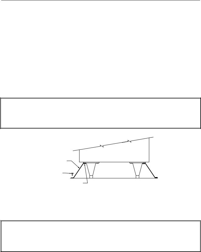
Restraints
Once the fryer has been positioned at the frying station, use a carpenter’s level placed across the top of the frypot to verify that the unit is level, both side-to-side and front-to-back.
To level fryers equipped with legs, the bottom of the legs can be screwed out up to one inch for leveling. Legs should also be adjusted so that the fryer(s) are at the proper height in the frying station.
For fryers equipped with casters, there are no built-in leveling devices. The floor where the fryers are installed must be level.
When the fryer is leveled in its final position, install the restraints provided with the unit to limit its movement so that it does not depend on or transmit stress to the electrical conduit or connection. Install the restraints in accordance with the provided instructions (see illustration below). If the restraints are disconnected for service or other reasons, they must be reconnected before the fryer is used.
 DANGER
Adequate means must be provided to limit the movement of this appliance without depending on or transmitting stress to electrical conduits or gas supply line. A restraint kit is provided with the fryer. If the restraint kit is missing contact your local Frymaster Factory Authorized Service Center (FASC) for part number 826-0900.
NOTE: If you need to relocate a fryer installed with legs, remove all weight from each leg before moving. If a leg becomes damaged, contact your service agent for immediate repair or replacement.
 DANGER
Hot oil can cause severe burns. Avoid contact. Under all circumstances, oil must be removed from the fryer before attempting to move it to avoid oil spills, falls, and severe burns. This fryer may tip and cause personal injury if not secured in a stationary position.
1-8
HIGH EFFICIENCY DECATHLON SERIES GAS FRYERS
CHAPTER 1: SERVICE PROCEDURES
1.3 Cleaning the Gas Valve Vent Tube (if applicable)
1.Set the fryer power switch and the gas valve to the OFF position.
2.Carefully unscrew the vent tube from the gas valve. NOTE: The vent tube may be straightened for ease in removal.
3.Pass a piece of wire through the tube to remove any obstruction. Remove the wire and blow through the tube to ensure it is clear.
4.Reinstall tube and bend so that the opening is pointing downward.
1.4 Adjusting Burner Manifold Gas Pressure
 WARNING
This task should be performed by qualified service personnel only.
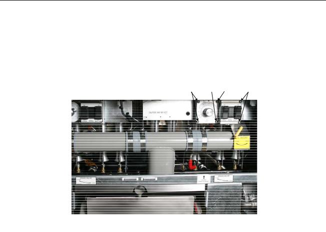
1.Ensure that the gas valve knob is in the OFF position.
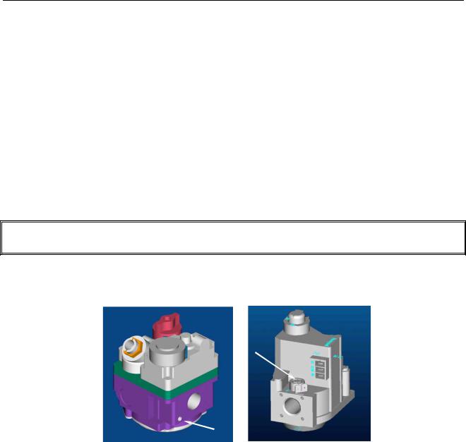
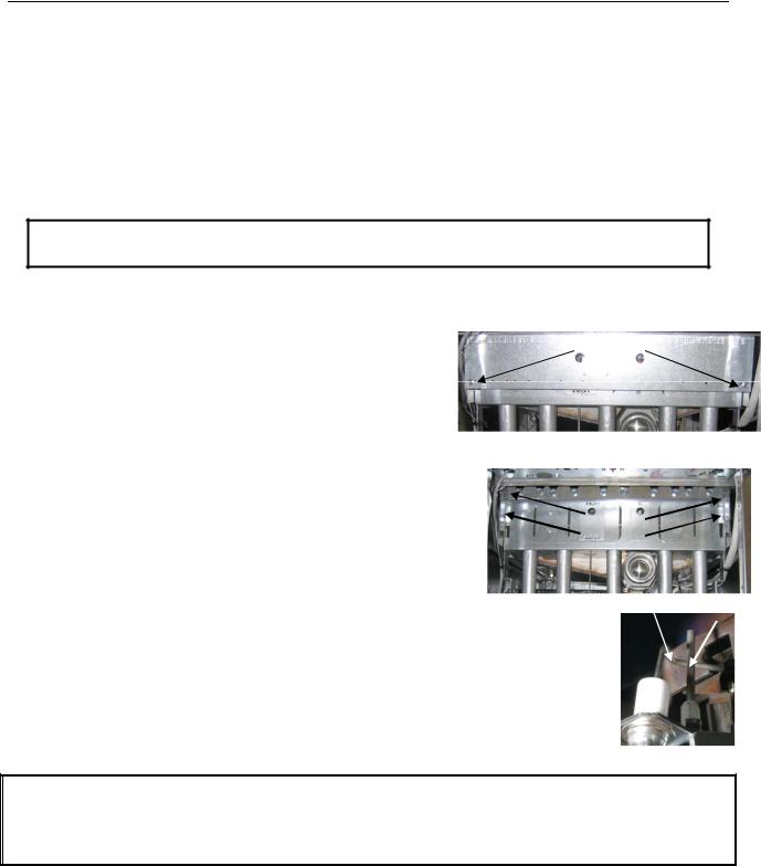
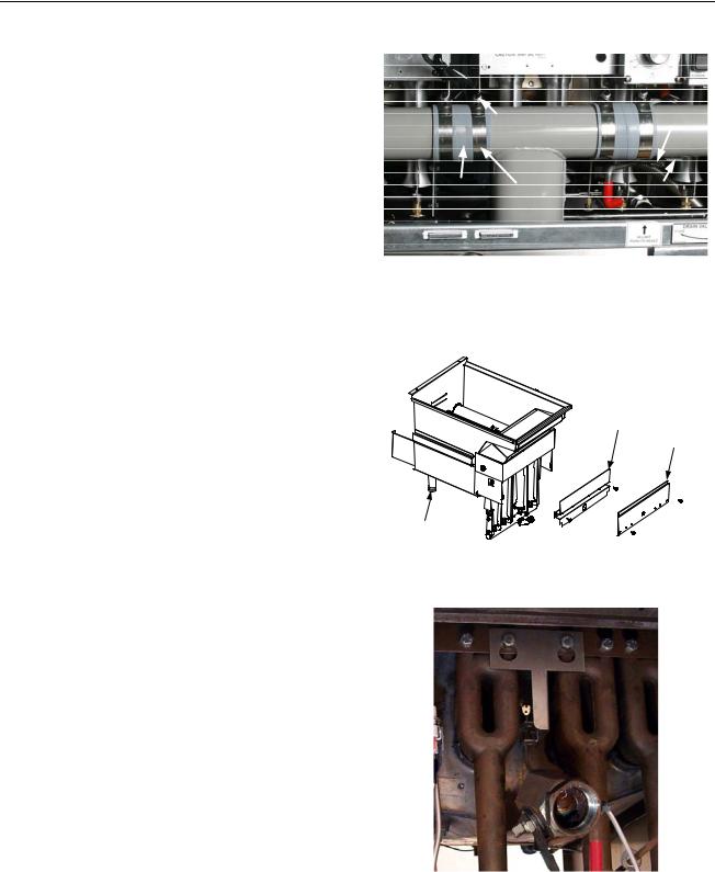
2.Remove the pressure tap plug from the gas valve (see arrows in photos below for location).
Pilot Ignition Valve |
Electronic |
(Line Voltage) |
Ignition Valve |
3.Insert the manometer fitting into the pressure tap hole.
4.Place the gas valve in the ON position then place the fryer power switch in the ON position. When the burner lights and continues to burn, check the gas pressure reading against the table on page 1-1.
5.To adjust burner gas pressure, remove the cap from the gas valve regulator and adjust to correct pressure.
6.Place the fryer power switch and the gas valve in the OFF position. Remove the manometer fitting from the pressure tap hole and reinstall the pressure tap plug.
1-9

HIGH EFFICIENCY DECATHLON SERIES GAS FRYERS
CHAPTER 1: SERVICE PROCEDURES
1.5 Adjusting the Pilot Flame
1.5.1 Main Pilot
1.Remove the cap from the pilot adjustment screw hole on the gas valve.
2.Using a small, flat-tipped screwdriver, turn the pilot adjusting screw counterclockwise to increase length of flame or clockwise to decrease length of flame. Adjust to obtain a flame from 1 inch to 1½ inches long.
3.Reinstall the pilot adjustment screw cap.
1.5.2 Trailing Pilot
Unlike older Decathlon units, current production HD units do not have a trailing pilot adjustment.
1.6 Calibrating the Thermatron
1.Fill the frypot to the lower OIL-LEVEL line with cooking oil. If solid shortening is used, it must be melted before starting the calibration procedure.
2.Ensure the fryer ON/OFF switch is in the OFF position and light the pilot.
3.Place the fryer ON/OFF switch in the ON position. Set the potentiometer dial to 325°F (162°C).
4.Allow the oil to equalize at setpoint temperature. This is evident when the burners have cycled on and off several times.
5.Insert a thermometer or pyrometer into the frypot within 3 inches of the probe bulb. Ensure the tip of the thermometer/pyrometer does not touch the frypot burner tube.
6.If the temperature on the thermometer is higher or lower than 325°F (162°C), the knob is out of calibration.
7.Calibrate the knob by first loosening the setscrews and slowly turning the knob to match the temperature reading of the thermometer. Tighten the setscrews, ensuring the knob does not move on the shaft during tightening.
8.Allow burners to cycle on and off several times, then recheck oil temperature as described in Step 5. If the thermostat dial temperature matches the thermometer temperature, the thermostat is calibrated. If not, repeat Step 7.
1-10
HIGH EFFICIENCY DECATHLON SERIES GAS FRYERS
CHAPTER 1: SERVICE PROCEDURES
1.7 Replacing Fryer Components
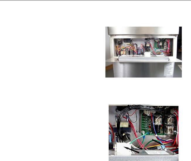
1.7.1 Replacing the Controller
1.Disconnect the fryer from the electrical supply.
2.Unscrew the two controller panel screws. The controller panel is hinged at the bottom and will swing open from the top.
Computer panel in “down” position.
3.Unplug the fryer wiring harness and ground wire from the back of the controller.
4.Remove the controller by lifting it from the
hinge slots in the fryer control panel frame.
5. Reverse the procedure to install a new
controller.
Disconnect the 15-pin connector and ground wire (arrows) from the computer.
1-11

HIGH EFFICIENCY DECATHLON SERIES GAS FRYERS
CHAPTER 1: SERVICE PROCEDURES
1.7.2Replacing Control Box Components including Ignition Module, Interface Board, Transformers, etc.
1.Disconnect the fryer from the electrical supply.
2.Unscrew the two controller panel screws. The controller panel is hinged at the bottom and will swing open from the top.
3.Locate the component to replace.
4.Mark the location of the wires to facilitate easy reassembly.
5.Disconnect the wires.
6.Remove the screws attaching the component to the control box.
7.Reverse steps to complete the replacement and return the fryer to service.
1-12
HIGH EFFICIENCY DECATHLON SERIES GAS FRYERS
CHAPTER 1: SERVICE PROCEDURES
1.7.3 Replacing the Temperature Probe; Controller-equipped Fryers
1. Disconnect the fryer from the electrical supply.
2.Drain cooking oil from the frypot. Allow the frypot to cool completely before proceeding.
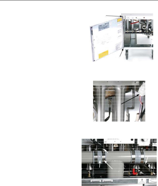
3.Remove fryer door for easier access to the temperature probe. First, remove top hinge
from bracket. Then, lift door off bottom hinge pin.
Remove the fryer door for easier access to the temperature probe.
4. Disconnect the probe harness connector (arrow). Use a pin pusher to remove plug from probe wires (probe side only). Retain the plug for re-assembly on new probe.
Disconnect the two-pin probe harness connector (arrow).
5.Remove the drain manifold. Only the drain tubes directly blocking the frypot being replaced require removal.
-Remove the nuts holding the drain valve strap onto the drain tube stud.
-Disconnect the Teflon tube at the back of the center dump tube piece and any other components attached to the tubes, including drain flush flexlines.
-Loosen the nut on each clamp holding the rubber boots and drain sections together.
-Carefully remove the tubes by pulling down at an angle, straight out of the drain valves, and working them gently out of the rubber boots. Set aside for reassembly.
Remove the nuts, Teflon tube (not pictured), clamp, boot, and drain tubes.
1-13
HIGH EFFICIENCY DECATHLON SERIES GAS FRYERS
CHAPTER 1: SERVICE PROCEDURES
1.7.3 Replacing the Temperature Probe; Controller-equipped Fryers (cont.)
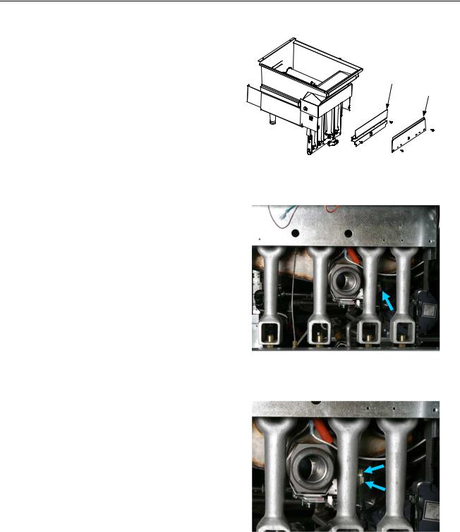
6.Remove the burner shield by loosening the screw on each end.
7.Remove the burner rail by loosening the
screw on each end. The burner rail secures the burners in the burner manifold. Be careful to ensure that the burners do not fall out of the gas manifold, as they might be damaged and dented.
Remove the burner rail and burner shield.
8.Remove the burners to gain access to the temperature probe and to ease frypot removal. Lean each burner slightly away from the frypot to clear the burner seal (metal box attached to frypot). Then, pull the burner up and off of the orifice. The burners should be easy to remove and do not require force.
9.Loosen and unscrew the compression nut and the pass-through nut completely from the frypot. Proceed to the next step before removing the probe from the frypot.
Remove burners to gain access to temperature probe (arrow).
Loosen and unscrew completely the compression nut (bottom arrow), then the pass-through nut (top arrow).
1-14
HIGH EFFICIENCY DECATHLON SERIES GAS FRYERS
CHAPTER 1: SERVICE PROCEDURES
1.7.3 Replacing the Temperature Probe; Controller-equipped Fryers (cont.)
10.Locate the temperature probe inside the frypot.
11.The temperature probe can be removed through the bottom of the frypot as follows: Ensure the two-pin connector has been removed from the probe wiring harness (step 4, above). Carefully bend the two tabs (one forward and toward the back) so the probe will clear the tabs. Remove the harness insulation. The probe can be pulled through the frypot from the bottom (complete step 7, above, prior to removing probe).
Locate the temperature probe.
12.Carefully remove the probe from the frypot. As the probe is removed, tilt the probe at an angle to facilitate removal (curved probes only).
13.Follow the steps on the next page to install the new temperature probe.
IMPORTANT: When installing new probe, use Loctite PST567 or equivalent pipe thread sealant on threads and ensure probe is positioned properly with the mounting hardware installed prior to tightening the compression nut. Once tightened, the probe cannot be repositioned.
After removing the probe mounting hardware, the temperature probe can be removed through the bottom of the frypot. Retain the mounting hardware for reassembly.
1-15
HIGH EFFICIENCY DECATHLON SERIES GAS FRYERS
CHAPTER 1: SERVICE PROCEDURES
Installing the New Temperature Probe:
1.Feed the probe wire through the probe nipple from the top side of the frypot.
2.Loosely install the bladder nut.
3.Mount the probe into the mounting hardware. Carefully bend the two tabs back into alignment to retain probe.
4.Tighten the bladder nut.
5.Install the insulation and plug.
1.7.4 Replacing the High-limit Thermostat
1.Turn fryer off and drain oil from the frypot. Allow the frypot to cool completely before proceeding.
2.Perform steps 1-4 in Section 1.7.1, Replacing the Controller.
3.Remove fryer door for easier access to the temperature probe. First, remove top hinge from bracket. Then, lift door off bottom hinge pin.
4.Remove two screws securing the high-limit mounting-bracket. Do not disconnect wires from high-limit at this time.
Remove screws (arrows) securing high-limit to fryer.
5.Loosen and completely unscrew the compression nut, then the pass-through nut on the frypot bottom. Proceed to the next step before removing high-limit from frypot.
Compression nut unscrewed. Unscrew the pass-through nut (arrow).
1-16
HIGH EFFICIENCY DECATHLON SERIES GAS FRYERS
CHAPTER 1: SERVICE PROCEDURES
1.7.4 Replacing the High-limit Thermostat (cont.)
6.Locate the high-limit probe inside the frypot. Carefully bend the outer tab at the rear of the high limit until the high limit can slid back and out of the retaining bracket.
Locate the high-limit probe.
7.Carefully pull high-limit capillary tube and bulb out of the frypot from the bottom.
Remove high-limit capillary tube and bulb from the bottom of the frypot.
1-17
HIGH EFFICIENCY DECATHLON SERIES GAS FRYERS
CHAPTER 1: SERVICE PROCEDURES
1.7.4 Replacing the High-limit Thermostat (cont.)
8.Mark and disconnect wires at the high-limit in the component box.
Mark and disconnect high-limit wiring (arrows). Reconnect wires to the same terminals on the replacement high-limit.
9.Remove high-limit from fryer by pulling the capillary tube and bulb through the component box opening (arrow). This may require removal of the control panel frame.
10.Reverse the above steps for high-limit installation.
IMPORTANT: When installing new high-limit, |
Component box opening (arrow). |
|
ensure the capillary |
tube and bulb are positioned |
|
properly with tab back in alignment prior to tightening |
|
|
the compression nut. |
Once tightened, the capillary |
|
tube cannot be repositioned. |
|
|
1-18
HIGH EFFICIENCY DECATHLON SERIES GAS FRYERS
CHAPTER 1: SERVICE PROCEDURES
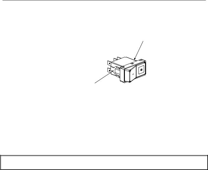
1.7.5 Replacing Rocker Switches
1.Disconnect the fryer from the electrical supply.
2.If switches are located in a control box within the fryer, remove the six screws securing the switch panel to the control box. Do not allow the switch panel to hang from the switch wiring harness or other wires.
1-19
HIGH EFFICIENCY DECATHLON SERIES GAS FRYERS
CHAPTER 1: SERVICE PROCEDURES
1.7.5 Replacing Rocker Switches (cont.)
3.Depress the retaining clips (see illustration below) and push the switch out of the slot. If there is a switch-guard present, retain it for installation of the replacement switch.
Depress clips on each side to remove switch from control panel.
4.Remove wires one at a time from the switch being removed and connect to the replacement switch until all wires are transferred.
5.Reverse the above steps for reassembly.
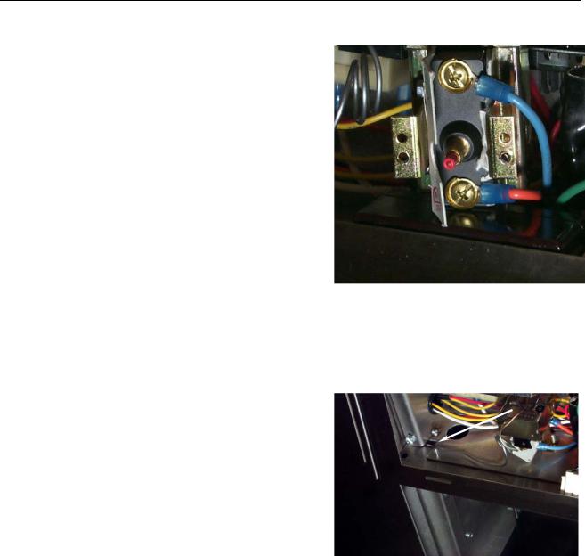
1.7.6 Replacing the Gas Valve
 DANGER
Drain the frypot or remove the handle from the drain valve before proceeding further.
1.Disconnect fryer from electrical and gas supplies.
2.Disconnect the wires from the gas valve terminal block, marking each wire to facilitate reconnections. For 120VAC gas valves, disconnect the black wire from the high-limit, then remove the bobtail connecting the white wire.
3.Remove the high-limit thermostat wire from the gas valve pilot coil (all but 120 VAC valves).
4.Remove the pilot gas line fitting from the gas valve.
5.Remove the pipe union collars to the left and right of the gas valve and remove the valve.
6.Remove the pipefitting from the old gas valve and install on the replacement valve, using Loctite PST567 or equivalent pipe thread sealant on threads. Do not apply sealant to the first two pipe threads. Doing so will clog and damage the gas valve.
7.Reverse steps 1-5 to install the replacement gas valve.
1-20
HIGH EFFICIENCY DECATHLON SERIES GAS FRYERS
CHAPTER 1: SERVICE PROCEDURES
1.7.7Replacing the Pilot Assembly
1.Remove the pilot tubing from the bottom of the pilot assembly.
2.If the pilot is an electronic ignition pilot, disconnect the ignition cable and the sense wire.
3.Remove the pilot mounting screw(s) from the pilot mounting bracket and remove the pilot.
4.Reverse the procedure to replace the pilot assembly.
NOTE: The above procedure is applicable to standing pilot, electronic ignition, and trailing pilot assemblies.
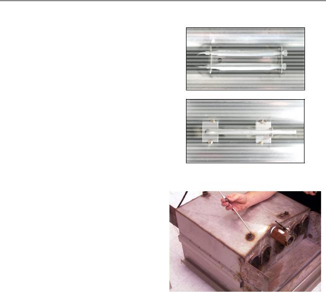
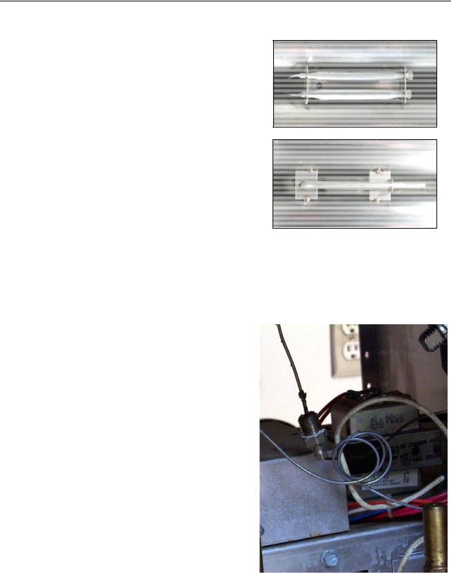
1.7.8 Adjusting the Ignitor Assembly
1.Disconnect the fryer from the electrical supply.
2.Remove the outer cover plate by removing two screws as shown in Figure 1.
3.Remove the air shutter plate if applicable by removing the four screws in the four corners as shown in Figure 2.
4.Gently bend the ignitor spark probe until the gap distance is approximately ¼” inch between the two points as shown in Figure 3.
5.Reverse steps to reassemble.
Figure 1
Figure 2
1.7.9 Replacing the Frypot
1.Open fryer doors and remove filter pan (if applicable). Ensure controller and all power switches are off. Drain and dispose of or store oil from all frypots
prior to moving fryer. |
Figure 3 |
|
 DANGER
Hot cooking oil will cause severe burns. Never attempt to move this appliance when filled with hot cooking oil or to transfer hot cooking oil from one container to another.
2.Turn gas valve off, then turn gas off at supply valve or meter. Disconnect supply line from gas manifold at rear of fryer.
1-21
HIGH EFFICIENCY DECATHLON SERIES GAS FRYERS
CHAPTER 1: SERVICE PROCEDURES
NOTE: If restraints are installed on the fryer, disconnect restraints prior to disconnecting the gas supply line.
3.Unplug fryer from electrical supply source.
4.Remove fryer door for easier access to the temperature probe. First, remove top hinge from bracket. Then, lift door off bottom hinge pin.
5.Remove the basket hanger from the flue cap by lifting up and off of fryer. Some units may have a built-in flue deflector on the basket hanger. Units with basket lifts will require the removal of the lift arms prior to removing the basket hanger.
6.Remove the top cap. It is held in place by one screw
on each side of the fryer. If the fryer has a controller
on the front, the top cap may also be held in place Removing the basket hanger from the flue cap. by two screws on the front of each pot. FPHD65
units may have two screws on each end of the top cap.
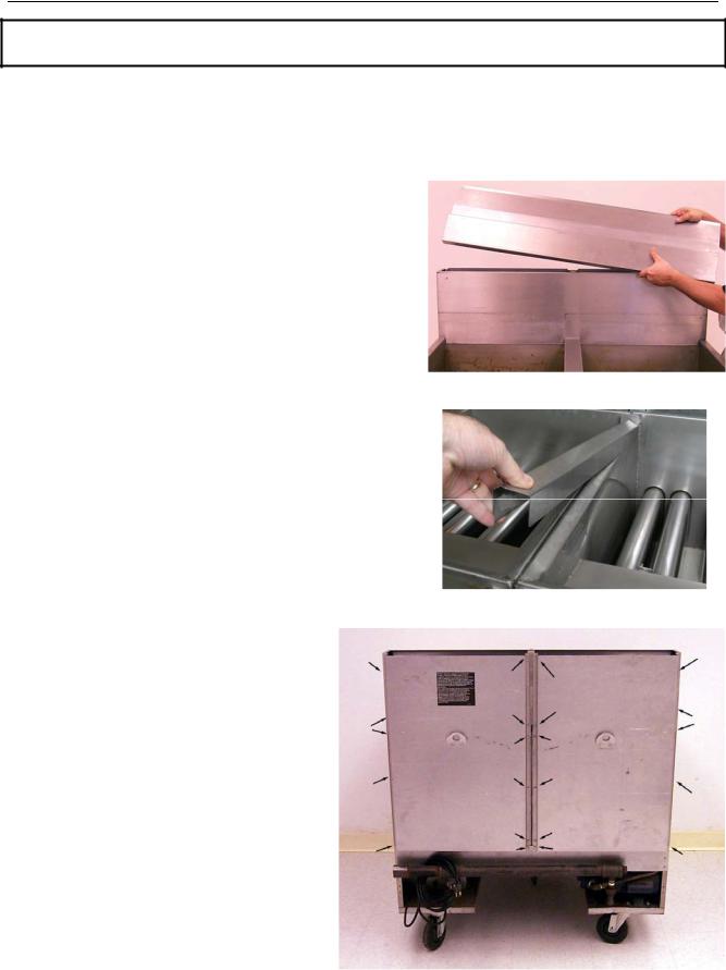
7.Remove the joiner strips on either side of the frypot. Be careful not to bend the joiner strip during removal.
Removing the joiner strip.
8.Remove back panels of the fryer. There may be both upper and lower panels and several screws secure them. Screw location and orientation will vary according to fryer model.
Typical screw locations on the back panel (may vary by
model).
1-22
HIGH EFFICIENCY DECATHLON SERIES GAS FRYERS
CHAPTER 1: SERVICE PROCEDURES
1.7.9 Replacing the Frypot (cont.)
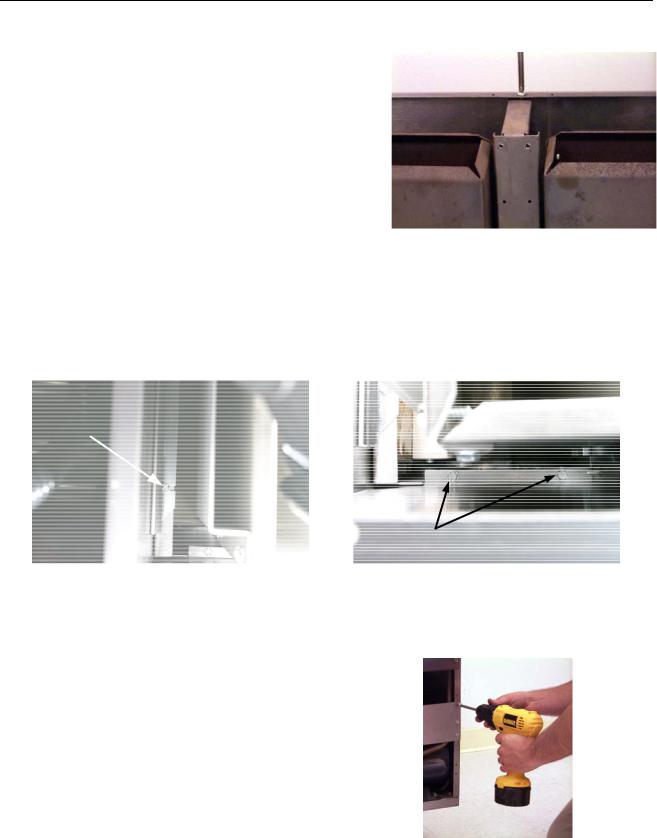
9.Remove screw securing brace (and back panel) to the flue cap. Support the brace with hand while removing screw to prevent brace from falling away. Remove brace and set aside for reassembly.
Removing brace holding back panel to flue cap.
10.Remove screws securing flue cap to frypot (access from above; a nut-driver with an extension or long screwdriver is required). Use care not to drop the screws into the flues. If this happens, the screws can be retrieved when the flue is removed (Step 12). Use a screwdriver or similar tool to free flue cap from frypots. Remove flue cap by lifting up and off of fryer.
Remove the screws (arrow) securing the flue cap to the frypot on the long edge. There will be two or three screws depending on configuration. (view from above, looking down into flue)
Remove the screws (arrows) securing the flue cap to the frypot on the short edge. There will be two screws on each end of the flue. (view from above, looking down into flue)
11. Remove gas manifold pipe for access to gas |
|
|
manifold shield by disconnecting at the unions. |
|
|
Ensure gas supply is shut off and supply line is |
|
|
disconnected prior to removing. |
Set gas |
|
manifold aside. Remove screws securing gas |
|
|
manifold shield. Remove shield to access oil- |
|
|
return plumbing components connected to the |
|
|
frypots. |
|
|
NOTE: For units without built-in filtration |
|
|
skip the steps pertaining to removal and |
Removing gas manifold shield. |
|
replacement of oil-return plumbing. |
|
|
|
1-23 |
|
HIGH EFFICIENCY DECATHLON SERIES GAS FRYERS
CHAPTER 1: SERVICE PROCEDURES
1.7.9 Replacing the Frypot (cont.)
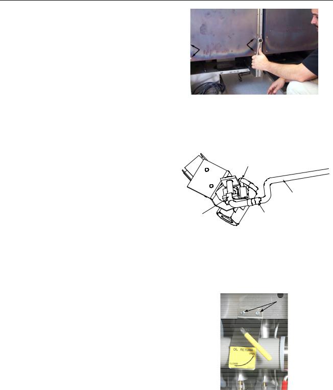
12.Remove screws securing flue to frypot (access from above; a nut-driver with an extension or long screwdriver is required). Retrieve any screws dropped into the flue during removal of the flue cap and frypot bracket.
13.Remove the clevis clip and oil return handle rod from the oil return valve at the rear of the fryer. Slip Section A of the clevis clip off of the oil return handle by pulling up on the rings. Slide the oil return handle out of the bracket and Section B of the clevis clip. Repeat for the drain flush handle (if applicable).
14.Loosen the two screws on the front of the oil return handle bracket at the front of the fryer. Remove the bracket and handle and set aside for reassembly. Repeat for the drain flush handle (if applicable).
Removing bolts (arrows) securing flue to frypot.
Disconnect oil-return handle from clevis clip and valve.
Oil-return handle bracket and screws.
1-24
HIGH EFFICIENCY DECATHLON SERIES GAS FRYERS
CHAPTER 1: SERVICE PROCEDURES
1.7.9 Replacing the Frypot (cont.)
15.Remove the drain manifold. Only the drain tubes directly blocking the frypot being replaced require removal.
-Remove the nuts holding the drain valve strap onto the drain tube stud.
-Disconnect the Teflon tube at the back of the center dump tube piece and any other components attached to the tubes, including drain flush flexlines.
-Loosen the nut on each clamp holding the rubber boots and drain sections together.
|
Nut |
Valve |
|
|
|
Boot |
Clamp |
Stud & |
|
Strap |
|
|
|
Drain manifold parts.
-Carefully remove the tubes by pulling down at an angle, straight out of the drain valves, and working them gently out of the rubber boots. Set aside for reassembly.
16.Remove the nipple attaching the oil return line to the bottom of the frypot at the rear of the fryer using a wrench. This may require removal of other pieces of the oil return manifold, as needed.
17.Remove the burner shield by loosening the screw on each end.
18.Remove the burners to gain access to the temperature probe and to ease removal. Remove one burner at a time. Loosen the two screws attaching the burner to the burner rail. Slide the burner up until the heads of the two screws reach the round key holes and lean it slightly toward from the frypot to clear the burner rail and seal (metal box attached to frypot). Then, pull the burner up and off of the orifice. The burners should be easy to remove and do not require force.
19.Remove the burner rail when all burners have been uninstalled. Loosen the screws on each end of the rail and set it aside.
Oil-return nipple, burner shield, and burner rail.
Remove drain valve handle and burners from fryer.
1-25
 Loading...