


Series FMCF, FMCFE, FMCFEC, MJCF, MJCFE, MJCFEC, KJ3FC, JCFX, J3F & J65X.
and Installation |
Series CF |
Manual Operation |
Fryers Gas |
|
|
NON-CE &
PRINTED IN THE UNITED STATES
Frymaster, a member of the Commercial Food Equipment Service Association, recommends using CFESA Certified Technicians.
24-Hour Service Hotline 1-800-551- |
*8195613* |
|
8633 |
||
www.frymaster.com |
||
|
||
Email: service@frymaster.com |
12/2015 |
NOTICE
This appliance is intended for professional use only and is to be operated by qualified personnel only. A Frymaster/DEAN Factory Authorized Servicer (FAS) or other qualified professional should perform installation, maintenance, and repairs. Installation, maintenance, or repairs by unqualified personnel may void the manufacturer’s warranty. See Chapter 1 of this manual for definitions of qualified personnel.
NOTICE
This equipment must be installed in accordance with the appropriate national and local codes of the country and/or region in which the appliance is installed. See NATIONAL CODE REQUIREMENTS in Chapter 2 of this manual for specifics.
NOTICE TO U.S. CUSTOMERS
This equipment is to be installed in compliance with the basic plumbing code of the Building Officials and Code Administrators International, Inc. (BOCA) and the Food Service Sanitation Manual of the U.S. Food and Drug Administration.
NOTICE
Drawings and photos used in this manual are intended to illustrate operational, cleaning and technical procedures and may not conform to onsite management operational procedures.
NOTICE TO OWNERS OF UNITS EQUIPPED WITH COMPUTERS
U.S.
This device complies with Part 15 of the FCC rules. Operation is subject to the following two conditions: 1) This device may not cause harmful interference, and 2) This device must accept any interference received, including interference that may cause undesired operation. While this device is a verified Class A device, it has been shown to meet the Class B limits.
CANADA
This digital apparatus does not exceed the Class A or B limits for radio noise emissions as set out by the ICES-003 standard of the Canadian Department of Communications.
Cet appareil numerique n’emet pas de bruits radioelectriques depassany les limites de classe A et B prescrites dans la norme NMB-003 edictee par le Ministre des Communcations du Canada.
 DANGER
Improper installation, adjustment, maintenance or service, and unauthorized alterations or modifications can cause property damage, injury, or death. Read the installation, operating, and service instructions thoroughly before installing or servicing this equipment. Only qualified service personnel may convert this appliance to use a gas other than that for which it was originally configured.
 DANGER
No structural material on the fryer should be altered or removed to accommodate placement of the fryer under a hood. Questions? Call the Frymaster/Dean Service Hotline at 1-800-551-8633.
ii

 DANGER
Adequate means must be provided to limit the movement of this appliance without depending upon the gas line connection. Single fryers equipped with legs must be stabilized by installing anchor straps. All fryers equipped with casters must be stabilized by installing restraining chains. If a flexible gas line is used, an additional restraining cable must be connected at all times when the fryer is in use.
 DANGER
The front ledge of the fryer is not a step! Do not stand on the fryer. Serious injury can result from slips or contact with the hot oil.
 DANGER
Do not store or use gasoline or other flammable liquids or vapors in the vicinity of this or any other appliance.
 DANGER
Instructions to be followed in the event the operator smells gas or otherwise detects a gas leak must be posted in a prominent location. This information can be obtained from the local gas company or gas supplier.
DANGER
The crumb tray in fryers equipped with a filter system must be emptied into a fireproof container at the end of frying operations each day. Some food particles can spontaneously combust if left soaking in certain shortening material.
 WARNING
Do not bang fry baskets or other utensils on the fryer’s joiner strip. The strip is present to seal the joint between the fry vessels. Banging fry baskets on the strip to dislodge shortening will distort the strip, adversely affecting its fit. It is designed for a tight fit and should only be removed for cleaning.
NOTICE
IF, DURING THE WARRANTY PERIOD, THE CUSTOMER USES A PART FOR THIS MANITOWOC EQUIPMENT OTHER THAN AN UNMODIFIED NEW OR RECYCLED PART PURCHASED DIRECTLY FROM FRYMASTER/DEAN, OR ANY OF ITS AUTHORIZED SERVICE CENTERS, AND/OR THE PART BEING USED IS MODIFIED FROM ITS ORIGINAL CONFIGURATION, THIS WARRANTY WILL BE VOID. FURTHER, FRYMASTER/DEAN AND ITS AFFILIATES WILL NOT BE LIABLE FOR ANY CLAIMS, DAMAGES OR EXPENSES INCURRED BY THE CUSTOMER WHICH ARISE DIRECTLY OR INDIRECTLY, IN WHOLE OR IN PART, DUE TO THE INSTALLATION OF ANY MODIFIED PART AND/OR PART RECEIVED FROM AN UNAUTHORIZED SERVICE CENTER.
NOTICE
The Commonwealth of Massachusetts requires any and all gas products to be installed by a licensed plumber or pipe fitter.
 WARNING
This appliance is not intended for use by children under the age of 16 or persons with reduced physical, sensory or mental capabilities, or lack of experience and knowledge, unless they have been given supervision concerning use of the appliance by a person responsible for their safety. Do not allow children to play with this appliance.
iii

CF Series Gas Fryers
TABLE OF CONTENTS
CHAPTER 1: General Information |
PAGE # |
|
|
||
1.1 |
Applicability and Validity .............................................................................................................. |
1-1 |
1.2 |
Parts Ordering and Service Information......................................................................................... |
1-1 |
1.3 |
Safety Information.......................................................................................................................... |
1-2 |
1.4 |
European Community (CE) Specific Information.......................................................................... |
1-2 |
1.5 |
Equipment Description................................................................................................................... |
1-3 |
1.6 |
Installation, Operating, and Service Personnel............................................................................... |
1-4 |
1.7 |
Definitions ...................................................................................................................................... |
1-4 |
1.8 |
Shipping Damage Claim Procedure ............................................................................................... |
1-5 |
CHAPTER 2: Installation Instructions |
|
|
2.1 |
General Installation Requirements ................................................................................................. |
2-1 |
2.2 |
Dimensions ..................................................................................................................................... |
2-4 |
2.3 |
Caster/Leg Installation.................................................................................................................... |
2-4 |
2.4 |
Pre-Connection Preparations .......................................................................................................... |
2-5 |
2.5 |
Connection to Gas Line .................................................................................................................. |
2-6 |
2.6 |
Converting to Another Gas Type.................................................................................................... |
2-9 |
CHAPTER 3: Operating Instructions |
|
|
3.1 |
Start-Up Procedure ......................................................................................................................... |
3-1 |
3.2 |
Boiling-Out the Frypot ................................................................................................................... |
3-4 |
3.3 |
Shutting the Fryer Down ................................................................................................................ |
3-5 |
3.4 |
Controller Operation and Programming ......................................................................................... |
3-5 |
CHAPTER 4: Filtration Instructions |
|
|
4.1 |
Draining and Manual Filtering ....................................................................................................... |
4-1 |
4.2 |
Filter Magic II Filtration System Operation ................................................................................... |
4-3 |
|
Preparing the Filter Unit for Use and/or Changing Filter Paper..................................................... |
4-3 |
|
Operation of the Filter Unit ............................................................................................................ |
4-6 |
CHAPTER 5: Preventive Maintenance |
|
|
5.1 |
Fryer Preventive Maintenance Checks and Services...................................................................... |
5-1 |
|
Daily Checks and Services ............................................................................................................. |
5-1 |
|
Weekly Checks and Services.......................................................................................................... |
5-2 |
|
Quarterly Checks and Services....................................................................................................... |
5-2 |
|
Semi-Annual Checks and Services................................................................................................. |
5-5 |
5.2 |
Filter Magic II Filtration System Preventive Maintenance Checks and Services .......................... |
5-5 |
5.3 |
Annual/Periodic System Inspection................................................................................................ |
5-6 |
CHAPTER 6: Operator Troubleshooting |
|
|
6.1 |
Introduction .................................................................................................................................... |
6-1 |
6.2 |
Troubleshooting Fryers with Solid State (Analog), Digital, or CM III.5 Controllers .................... |
6-2 |
6.3 |
Troubleshooting Fryers with Thermostat Controls......................................................................... |
6-3 |
6.4 |
Troubleshooting the Built-In Filtration System.............................................................................. |
6-4 |
6.5 |
Troubleshooting Abnormal Burner Operation................................................................................ |
6-6 |
iv

CF SERIES GAS FRYERS
CHAPTER 1: INTRODUCTION
1.1 Applicability and Validity
The CF Series Gas Fryer model family has been approved by the European Union for sale and installation in the following EU countries: AT, BE, DE, DK, ES, FI, FR, GB, IE, IT, LU, NL, NO, PT and SE.
This manual is applicable to and valid for all CF Series Gas Fryer units sold in Englishspeaking countries, including those in the European Union. Where conflicts exist between instructions and information in this manual and local or national codes of the country in which the equipment is installed, installation and operation shall comply with those codes.
This appliance is only for professional use and shall be used by qualified personnel only, as defined in Section 1.7.
1.2 Parts Ordering and Service Information
In order to assist you as quickly as possible, the Factory Authorized Servicer (FAS) or Service Department representative requires certain information about your equipment. Most of this information is printed on a data plate affixed to the inside of the fryer door.
Parts orders must be placed directly with your local FAS or distributor. Your nearest Frymaster FAS is accessible at www.frymaster.com or you can contact the Frymaster Service Department at 1-800- 24-FRYER or 1-318-865-1711.
When ordering parts, the following information is required:
Model Number:
Serial Number:
Type of Gas or Voltage:
Item Part Number:
Quantity Needed:
Service information may be obtained by contacting your local FAS. Information may also be obtained by calling the Frymaster Technical Service Department at 1-800-551-8633 or 1-318-865- 1711.
When requesting service, please have the following information ready:
Model Number:
Serial Number:
Type of Gas:
1-1
CF SERIES GAS FRYERS
CHAPTER 1: INTRODUCTION
In addition to the model number, serial number, and type of gas, please be prepared to describe the nature of the problem and have ready any other information that you think may be helpful in solving your problem.
1.3 Safety Information
Before attempting to operate your unit, read the instructions in this manual thoroughly.
Your fryer is equipped with two automatic safety features:
High temperature detection shuts off gas to the burner assembly should the controlling thermostat fail.
A safety switch built into the drain valve of units with built-in filtration systems prevents burner ignition with the drain valve even partially open.
Throughout this manual, you will find notations enclosed in double-bordered boxes similar to the ones below.
 CAUTION
CAUTION boxes contain information about actions or conditions that may cause or result in a malfunction of your system.
 WARNING
WARNING boxes contain information about actions or conditions that may cause or result in damage to your system, and which may cause your system to malfunction.
 DANGER
DANGER boxes contain information about actions or conditions that may cause or result in injury to personnel, and which may cause damage to your system and/or cause your system to malfunction.
1.4 European Community (CE) Specific Information
The European Community (CE) has established certain specific standards regarding equipment of this type. Whenever there is a difference between CE and non-CE standards, the information or instructions concerned are identified in tables.
1-2

CF SERIES GAS FRYERS
CHAPTER 1: INTRODUCTION
1.5 Equipment Description
CF Series gas fryers are specifically designed for high volume frying, especially fish, chicken and other breaded products. Models in this series include FMCF, FMCFE, FMCFEC, MJCF, MJCFE, MJCFEC, KJ3FC and J65X variants. (The J65X variant is a drop-in unit without cabinetry.) Fryers in this series may be equipped with built-in Filter Magic filtration systems (FMCF variants), or may be configured for manual filtration (MJCF variants). All models may be configured for electrical power supplies ranging from 120 to 240 VAC.
FMCF, MJCF AND J65X models utilize a combination gas valve to control the burner, but do not require an external AC power source. An AC power source is required for these models when equipped with built-in filtration systems.
FMCFE, KJ3FC and MJCFE models utilize a combination gas valve to control the burner and require an external AC power source. The electrical power supply to the gas valve is controlled by a manually-operated thermostat controller or a computer/controller. The FMCFEC and MJCFEC models are equipped with Computer Magic III.5 computers. The KJ3FC variants are equipped with user-supplied or KFC-1 computers.
All models are of an open-pot design with no tubes and have a hand-sized opening into the deep cold zone, which makes cleaning the stainless frypot quick and easy.
Fryers equipped with built-in filtration systems are shipped completely assembled. Fryers without built-in filtration require installation of legs or optional casters at point of use. All fryers are shipped with a package of standard accessories. Each fryer is adjusted, tested, and inspected at the factory before crating for shipment.
Frypots are constructed of welded, heavygauge stainless steel. Heating is supplied by a burner assembly having multiple gas jets, which are focused on ceramic targets located around the lower side of the frypot. The burner assembly can be configured for natural gas, propane, or manufactured gas, as required by the customer. A drain is tapped into the center of the frypot, with a frontcontrolled manual ball valve.
Each fryer is equipped with a thermostat probe for precise temperature control. The probe is located on the centerline of the frypot for rapid response to changes in loads and to provide the most accurate temperature measurement.
CF Series fryers may be equipped with an optional melt cycle feature, which pulses the burner on and off at a controlled rate. The melt cycle feature is designed to prevent scorching and uneven heating of the frypot for customers who use solid shortening.
The controls on your fryer vary depending on the model and configuration purchased. Control options include thermostat controls, solid state (analog) controllers, digital controllers, KFC-1, Fastron or Computer Magic III.5 computers. Each type is covered in a separate manual provided with your equipment.
1-3

CF SERIES GAS FRYERS
CHAPTER 1: INTRODUCTION
1.6 Installation, Operating, and Service Personnel
Operating information for Frymaster equipment has been prepared for use by qualified and/or authorized personnel only, as defined in Section 1.7.
All installation and service on Frymaster equipment must be performed by qualified, certified, licensed, and or/authorized installation or service personnel, as defined in Section 1.7.
1.7 Definitions
QUALIFIED AND/OR AUTHORIZED OPERATING PERSONNEL
Qualified/authorized operating personnel are those who have carefully read the information in this manual and have familiarized themselves with the equipment functions, or who have had previous experience with the operation of the equipment covered in this manual.
QUALIFIED INSTALLATION PERSONNEL
Qualified installation personnel are individuals, or firms, corporations, or companies which, either in person or through a representative, are engaged in and are responsible for the installation of gas-fired appliances. Qualified personnel must be experienced in such work, be familiar with all gas precautions involved, and have complied with all requirements of applicable national and local codes.
QUALIFIED SERVICE PERSONNEL
Qualified service personnel are those that are familiar with Frymaster equipment and who have been authorized by Frymaster, L.L.C. to perform service on Frymaster equipment. All authorized service personnel are required to be equipped with a complete set of service and parts manuals, and to stock a prescribed minimum amount of Frymaster equipment parts.
Your nearest Frymaster FAS is accessible at www.frymaster.com or you can contact the Frymaster Service Department at 1-800-24-FRYER or 1-318-865-1711.
Failure to use qualified service personnel will void the Frymaster Warranty on your equipment.
1-4
CF SERIES GAS FRYERS
CHAPTER 1: INTRODUCTION
1.8 Shipping Damage Claim Procedure
Your Frymaster equipment was carefully inspected and packed before leaving the factory. The transportation company assumes full responsibility for safe delivery upon acceptance of the equipment for transport.
What to do if your equipment arrives damaged:
1.File a claim for damages immediately, regardless of the extent of damages.
2.Inspect for and record all visible loss or damage, and ensure that this information is noted on the freight bill or express receipt and is signed by the person making the delivery.
3.Concealed loss or damage that was unnoticed until the equipment was unpacked should be recorded and reported to the freight company or carrier immediately upon discovery. A concealed damage claim must be submitted within 15 days of the date of delivery. Ensure that the shipping container is retained for inspection.
FRYMASTER L.L.C. DOES NOT ASSUME
RESPONSIBILITY FOR DAMAGE OR
LOSS INCURRED IN TRANSIT.
RETAIN AND STORE THIS MANUAL IN A SAFE PLACE FOR FUTURE USE.
1-5

CF SERIES GAS FRYERS
CHAPTER 2: INSTALLATION INSTRUCTIONS
2.1 General Installation Requirements
Qualified, licensed, and/or authorized installation or service personnel, as defined in Section 1.7 of this manual, should perform all installation and service on Frymaster equipment.
Conversion of this appliance from one type of gas to another should only be performed by qualified, licensed, and/or authorized installation or service personnel as defined in Section 1.7 of this manual.
Failure to use qualified, licensed, and/or authorized installation or service personnel (as defined in Section 1.7 of this manual) to install, convert to another gas type or otherwise service this equipment will void the Frymaster warranty and may result in damage to the equipment or injury to personnel.
Where conflicts exist between instructions and information in this manual and local or national codes or regulations, installation and operation shall comply with the codes or regulations in force in the country in which the equipment is installed.
 DANGER
Building codes prohibit a fryer with its open tank of hot oil being installed beside an open flame of any type, including those of broilers and ranges.
Upon arrival, inspect the fryer carefully for visible or concealed damage. (See Shipping Damage Claim Procedure in Chapter 1.) If there is no damage, remove the fryer from the pallet. Discard the box.
 DANGER
Frymaster appliances equipped with legs are for stationary installations. Appliances fitted with legs must be lifted during movement to avoid damage to the appliance and bodily injury. For movable installations, optional equipment casters must be used. Questions? Call 1-800-551-8633.
PROPER INSTALLATION IS ESSENTIAL FOR EFFICIENT, TROUBLE-FREE OPERATION OF YOUR FRYER. ANY UNAUTHORIZED ALTERATIONS MADE TO THIS EQUIPMENT WILL VOID THE FRYMASTER WARRANTY.
Upon arrival, inspect the fryer carefully for visible or concealed damage. (See Shipping Damage Claim Procedure in Chapter 1.)
2-1
CF SERIES GAS FRYERS
CHAPTER 2: INSTALLATION INSTRUCTIONS
CLEARANCE AND VENTILATION
 DANGER
No structural material on the fryer should be altered or removed to accommodate placement of the fryer under a hood. Questions? Call the Frymaster/Dean Service Hotline at 1-800-551-8633.
 DANGER
This appliance must be installed with sufficient ventilation to prevent the occurrence of unacceptable concentrations of substances harmful to the health of personnel in the room in which it is installed.
The fryer(s) must be installed with a 6" (150 mm) clearance at both sides and back when installed adjacent to combustible construction; no clearance is required when installed adjacent to noncombustible construction. A minimum of 24" (600 mm) clearance should be provided at the front of the fryer.
One of the most important considerations of efficient fryer operation is ventilation. Ensure the fryer is installed so that products of combustion are removed efficiently, and that the kitchen ventilation system does not produce drafts that interfere with proper burner operation.
The fryer flue opening must not be placed close to the intake of the exhaust fan, and the fryer must never have its flue extended in a "chimney" fashion. An extended flue will change the combustion characteristics of the fryer, causing longer recovery time. It also frequently causes delayed ignition. To provide the airflow necessary for good combustion and burner operation, the areas surrounding the fryer front, sides, and rear must be kept clear and unobstructed.
Fryers must be installed in an area with an adequate air supply and adequate ventilation. Adequate distances must be maintained from the flue outlet of the fryer to the lower edge of the ventilation filter bank. Filters should be installed at an angle of 45 degrees. Place a drip tray beneath the lowest edge of the filter. For U.S. installation, NFPA standard No. 96 states, "A minimum distance of 18 in. (450 mm) should be maintained between the flue outlet and the lower edge of the grease filter. " Frymaster recommends that the minimum distance be 24 in. (600 mm) from the flue outlet to the bottom edge of the filter when the appliance consumes more than 120,000 BTU per hour.
Information on construction and installation of ventilating hoods can be found in the NFPA standard cited above. A copy of the standard may be obtained from the National Fire Protection Association, Battery March Park, Quincy, MA 02269.
2-2
CF SERIES GAS FRYERS
CHAPTER 2: INSTALLATION INSTRUCTIONS
NATIONAL CODE REQUIREMENTS
The type of gas for which the fryer is equipped is stamped on the data plate attached to the inside of the fryer door. Connect a fryer stamped "NAT" only to natural gas, those stamped "PRO" only to propane gas, and those stamped "MFG" only to manufactured gas.
Installation shall be made with a gas connector that complies with national and local codes, and, where applicable, CE codes. Quick-Disconnect devices, if used, shall likewise comply with national, local, and, if applicable, CE codes.
AUSTRALIAN REQUIREMENTS
To be installed in accordance with AS 5601, local authority, gas, electricity, and any other relevant statutory regulations
ELECTRICAL GROUNDING REQUIREMENTS
All electrically operated appliances must be grounded in accordance with all applicable national and local codes, and, where applicable, CE codes. A wiring diagram is located on the inside of the fryer door. Refer to the rating plate on the inside of the fryer door for proper voltages.
 DANGER
If this appliance is equipped with a three-prong (grounding) plug for your protection against electrical shock, it must be plugged directly into a properly grounded threeprong receptacle. Do not cut, remove, or otherwise bypass the grounding prong on this plug!
 DANGER
This equipment requires electrical power for operation. Place the gas control valve in the OFF position in case of a prolonged power outage. Do not attempt to use the equipment during a power outage.
FCC COMPLIANCE
The user is cautioned that any changes or modifications to Frymaster computers not expressly approved by the party responsible for compliance could void the user’s authority to operate the equipment. Frymaster computers have been tested and found to comply with the limits for a Class A digital device, pursuant to Part 15 of the FCC rules. While these devices are verified as Class A devices, they have been shown to meet the Class B limits. These limits are designed to provide reasonable protection against harmful interference when the equipment is operated in a commercial environment. This equipment generates, uses, and can radiate radio frequency energy and, if not installed and used in accordance with the instruction manual, may cause harmful interference to radio communications. Operation of the equipment in a residential area is likely to cause harmful interference in which case the user will be required to correct the interference at the user’s expense.
2-3
CF SERIES GAS FRYERS
CHAPTER 2: INSTALLATION INSTRUCTIONS
If necessary, the user should consult the dealer or an experienced radio and television technician for additional suggestions.
The user may find the booklet "How to Identify and Resolve Radio-TV Interference Problems" helpful. It is prepared by the Federal Communications Commission and is available from the U.S. Government Printing Office, Washington, DC 20402, Stock No. 004-000-00345-4.
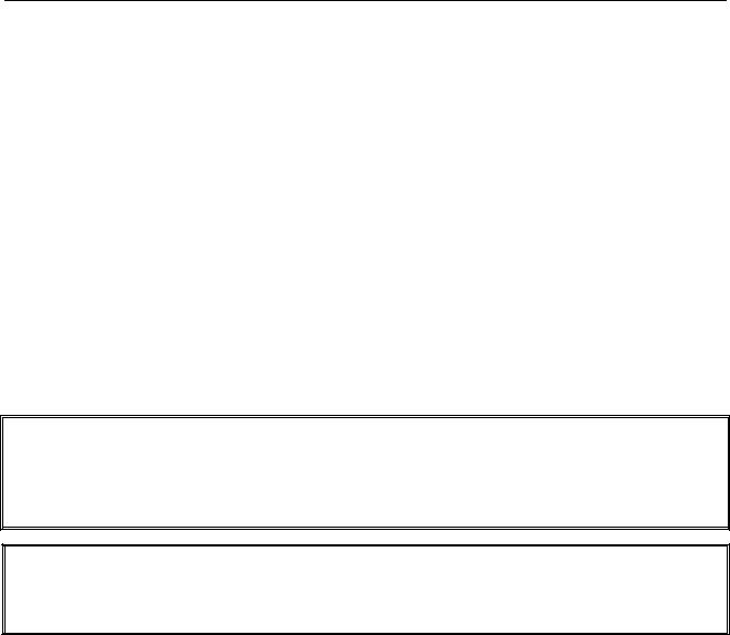
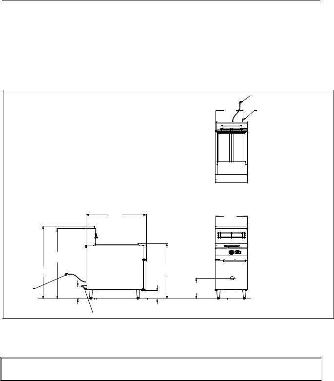
2.2 Dimensions
|
|
|
|
CORDSET |
|
|
|
18.18 |
3/4" NPT GAS CONNECTION |
|
|
|
[462] |
|
|
|
|
|
|
|
DIMENSIONS |
INCHES |
|
|
|
|
[MM] |
|
|
|
|
|
TOP VIEW |
|
|
39.86 |
|
20.83 |
|
|
[1013] |
|
|
|
|
|
[529] |
|
|
|
|
|
|
|
|
46.15 |
|
|
|
|
[1172] |
|
|
|
|
47.80 |
36.48 |
CENTER |
|
|
[1214] |
[927] |
OF DRAIN |
|
|
|
|
TUBE |
|
CORDSET |
|
|
13.63 |
|
8.28 |
5.50 |
[346] |
|
|
|
|
|||
|
[210] |
|
|
|
|
[140] |
|
|
|
|
|
|
|
3/4" NPT GAS CONNECTION |
SIDE VIEW FRYER |
FRONT VIEW |
|
|
2.3 Caster/Leg Installation
 DANGER
DO NOT install this appliance without legs or casters.
Depending upon the specific configuration ordered, the fryer might have been shipped without installed casters or legs. If casters or legs are installed, you may skip this section and proceed to Section 2.3, Pre-Connection Preparations.
2-4
CF SERIES GAS FRYERS
CHAPTER 2: INSTALLATION INSTRUCTIONS
If your fryer requires the installation of casters/legs, install them in accordance with the instructions included in your accessory package.
2.4 Pre-Connection Preparations
 DANGER
Do not connect this appliance to the gas supply before completing each step in this section.
After the fryer has been positioned under the fry station exhaust hood, ensure the following has been accomplished:
1.Adequate means must be provided to limit the movement of fryers without depending upon the gas line connections. If a flexible gas hose is used, a restraining cable must be connected at all times when the fryer is in use. The restraining cable and installation instructions are packed with the flexible hose in the accessories box that was shipped with your unit.
2.Single unit fryers must be stabilized by installing restraining chains on fryers equipped with casters or anchor straps on fryers equipped with legs. Follow the instructions shipped with the casters/legs to properly install the chains or straps.
 DANGER
Do not attach an apron drain board to a single fryer. The fryer may become unstable, tip over, and cause injury. The appliance area must be kept free and clear of combustible materials at all times.
3.Level fryers equipped with legs by screwing out the legs approximately 1 inch, and then adjust them so that the fryer is level and at the proper height in the exhaust hood. Frymaster recommends that the minimum distance from the flue outlet to the bottom edge of the filter be 24 inches (600 mm) when the appliance consumes more than 120,000 BTU per hour.
For fryers equipped with casters, there are no built-in leveling devices. The floor where the fryer is to be installed must be level.
4.Test the fryer electrical system: Verify correct voltage and connect per National codes and regulations.
a.Plug the fryer electrical cord(s) into a grounded electrical receptacle.
b.Place the power switch in the ON position.
For fryers equipped with thermostat controls, verify that the power and heat lights are lit.
For fryers having computer or digital displays, verify that the display indicates
2-5
CF SERIES GAS FRYERS
CHAPTER 2: INSTALLATION INSTRUCTIONS
c.Place the fryer power switch in the OFF position. Verify that the power and heat lights are out, or that the display is blank.
5.Refer to the data plate on the inside of the fryer door to verify that the fryer burner is configured for the proper type of gas before connecting the gas line quick-disconnect device or piping from the gas supply line.
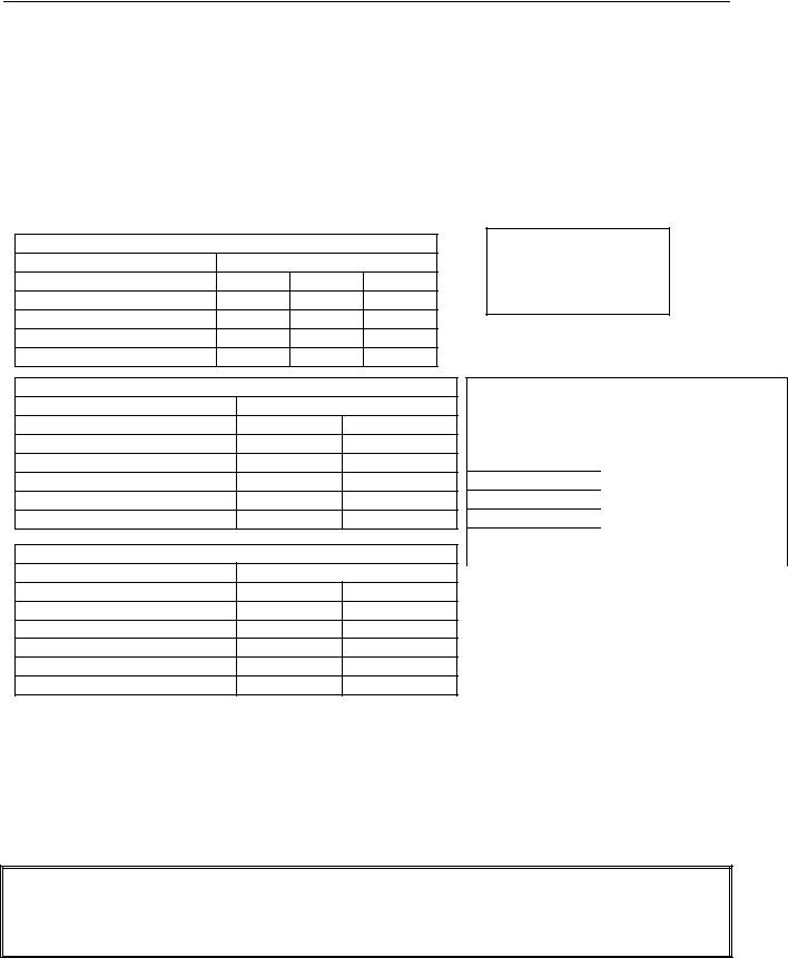
6.Verify the minimum and maximum gas supply pressures for the type of gas to be used in accordance with the accompanying tables:
CE Standard for Incoming Gas Pressure
|
Model CF |
|
|
Gas Type |
G20 |
G25 |
G31 |
Pressure (mbar) |
20 |
20 25 |
37 50 |
Orifice Size (mm) |
1.40 |
1.40 |
0.86 |
Number of Orifices |
18 |
18 |
18 |
Manifold Pressure (mbar) |
7,5 |
10 |
20,6 |
Non CE Standard for Incoming Gas Pressure
|
Model CF |
|
Gas Type |
Nat |
LP |
Min Pressure W.C/kpa/mbar |
6/1.49/14.93 |
11/2.74/27.37 |
Max Pressure W.C/kpa/mbar |
14/3.48/34.84 |
14/3.48/34.84 |
Orifice Size (mm) |
1.45 |
0.86 |
Number of Orifices |
18 |
18 |
Manifold Pressure (WC) |
3.5 |
8.25 |
Korea Standard for Incoming Gas Pressure |
|
|
|
Model CF |
|
Gas Type |
LNG (Natural) |
LPG (Propane) |
Min Pressure W.C/kpa/mbar |
4/1.00/10.00 |
9.2/2.30/23.00 |
Max Pressure W.C/kpa/mbar |
10/2.50/25.00 |
13.2/3.30/33.00 |
Orifice Size (mm) |
1.40 |
0.90 |
Number of Orifices |
18 |
18 |
Manifold Pressure (WC) |
3.5 |
8.25 |
NOTE: Gas specifications are included on appliance data plate located inside the door.
Australian Standard for Incoming Gas Pressure
|
Model CF |
|
Gas Type |
Nat |
LP |
Min Pressure |
1.13 kpa |
2.7 kpa |
Max Pressure |
5.0 kpa |
7.0 kpa |
Orifice Size (mm) |
1.4 |
0.90 |
Number of Orifices |
18 |
18 |
Manifold Pressure |
0.90 kpa |
2.30 kpa |
Gas Consumption |
158.2Mj |
158.2Mj |
(per hour) |
|
|
7.For fryers equipped with a built-in filter system and/or basket lifts, plug the electrical cord(s) into a power receptacle behind the fryer.
2.5 Connection to Gas Line
 DANGER
Before connecting new pipe to this appliance, the pipe must be blown out thoroughly to remove all foreign material. Foreign material in the burner and gas controls will cause improper and dangerous operation.
2-6
 Loading...