


BIELA14
This equipment chapter is to be
installed in the Fryer Section of the
Equipment Manual.
MANUFACTURED
OPERATOR’S MANUAL
FRYMASTER BIELA14 SERIES GEN II LOV™
ELECTRIC FRYER
BY
Do Not Store or use gasoline or other
flammable vapors and liquids in the
vicinity of this or any other appliance.
FOR YOUR SAFETY
8700 Line Ave.
SHREVEPORT, LOUISIANA 71106
PHONE: 1-318-865-1711
TOLL FREE: 1-800-551-8633
1-800-24 FRYER
FAX: 1-318-219-7135
TABLE OF CONTENTS
WARRANTY STATEMENT ................................................................................................... Page i
INTRODUCTION ................................................................................................................... Page 1-1
INSTALLATION INSTRUCTIONS ....................................................................................... Page 2-1
OPERATING INSTRUCTIONS ............................................................................................. Page 3-1
M3000 COMPUTER INSTRUCTIONS ................................................................................. Page 4-1
OPERATING THE BUILT-IN FILTRATION SYSTEM ........................................................... Page 5-1
PREVENTIVE MAINTENANCE ............................................................................................ Page 6-1
OPERATOR TROUBLESHOOTING ..................................................................................... Page 7-1
WIRING DIAGRAMS ............................................................................................................. Page 8-1
Frymaster L.L.C., 8700 Line Avenue, Shreveport, LA 71106
PHONE 318-865-1711 FAX 318-219-7135
PRINTED IN THE UNITED STATES SERVICE HOTLINE 1-800-24-FRYER APRIL 2011
*8196442*
NOTICE
IF, DURING THE WARRANTY PERIOD, THE CUSTOMER USES A PART FOR THIS
MANITOWOC FOOD SERVICE EQUIPMENT OTHER THAN AN UNMODIFIED NEW OR
RECYCLED PART PURCHASED DIRECTLY FROM FRYMASTER DEAN, OR ANY OF ITS
FACTORY AUTHORIZED SERVICE CENTERS, AND/OR THE PART BEING USED IS
MODIFIED FROM ITS ORIGINAL CONFIGURATION, THIS WARRANTY WILL BE VOID.
FURTHER, FRYMASTER DEAN AND ITS AFFILIATES WILL NOT BE LIABLE FOR ANY
CLAIMS, DAMAGES OR EXPENSES INCURRED BY THE CUSTOMER WHICH ARISE
DIRECTLY OR INDIRECTLY, IN WHOLE OR IN PART, DUE TO THE INSTALLATION OF ANY
MODIFIED PART AND/OR PART RECEIVED FROM AN UNAUTHORIZED SERVICE CENTER.
NOTICE
This appliance is intended for professional use only and is to be operated by qualified
personnel only. A Frymaster Authorized Service Agency (ASA) or other qualified
professional should perform installation, maintenance, and repairs. Installation,
maintenance, or repairs by unqualified personnel may void the manufacturer’s warranty.
See Chapter 1 of this manual for definitions of qualified personnel.
NOTICE
This equipment must be installed in accordance with the appropriate national and local
codes of the country and/or region in which the appliance is installed. See NATIONAL
CODE REQUIREMENTS in Chapter 2 of this manual for specifics.
NOTICE TO U.S. CUSTOMERS
This equipment is to be installed in compliance with the basic plumbing code of the
Building Officials and Code Administrators International, Inc. (BOCA) and the Food Service
Sanitation Manual of the U.S. Food and Drug Administration.
NOTICE
Drawings and photos used in this manual are intended to illustrate operational, cleaning
and technical procedures and may not conform to onsite management operational
procedures.
NOTICE TO OWNERS OF UNITS EQUIPPED WITH COMPUTERS
U.S.
This device complies with Part 15 of the FCC rules. Operation is subject to the following
two conditions: 1) This device may not cause harmful interference, and 2) This device must
accept any interference received, including interference that may cause undesired
operation. While this device is a verified Class A device, it has been shown to meet the
Class B limits.
CANADA
This digital apparatus does not exceed the Class A or B limits for radio noise emissions as
set out by the ICES-003 standard of the Canadian Department of Communications.
Cet appareil numerique n’emet pas de bruits radioelectriques depassany les limites de
classe A et B prescrites dans la norme NMB-003 edictee par le Ministre des Communcations
du Canada.
DANGER
Improper installation, adjustment, maintenance or service, and unauthorized alterations or
modifications can cause property damage, injury, or death. Read the installation, operating,
and service instructions thoroughly before installing or servicing this equipment.
DANGER
The front ledge of this appliance is not a step! Do not stand on the appliance. Serious
injury can result from slips or contact with the hot oil.
DANGER
Do not store or use gasoline or other flammable liquids or vapors in the vicinity of this or
any other appliance.
DANGER
The crumb tray in fryers equipped with a filter system must be emptied into a fireproof
container at the end of frying operations each day. Some food particles can spontaneously
combust if left soaking in certain shortening material.
WARNING
Do not bang fry baskets or other utensils on the fryer’s joiner strip. The strip is present to
seal the joint between the fry vessels. Banging fry baskets on the strip to dislodge
shortening will distort the strip, adversely affecting its fit. It is designed for a tight fit and
should only be removed for cleaning.
DANGER
Adequate means must be provided to limit the movement of this appliance without
depending on or transmitting stress to the electrical conduit. A restraint kit is provided with
the fryer. If the restraint kit is missing contact your local KES.
DANGER
This fryer has a power cord (three-phase) for each frypot and a single five-wire cord for the
entire system. Prior to movement, testing, maintenance and any repair on your Frymaster
fryer; disconnect ALL electrical power cords from the electrical power supply.
DANGER
Keep all items out of drains. Closing actuators may cause damage or injury.
NOTICE
The instructions in this manual for using a bulk oil system for filling and discarding oil are
for an RTI system. These instructions may not be applicable to other bulk oil systems.
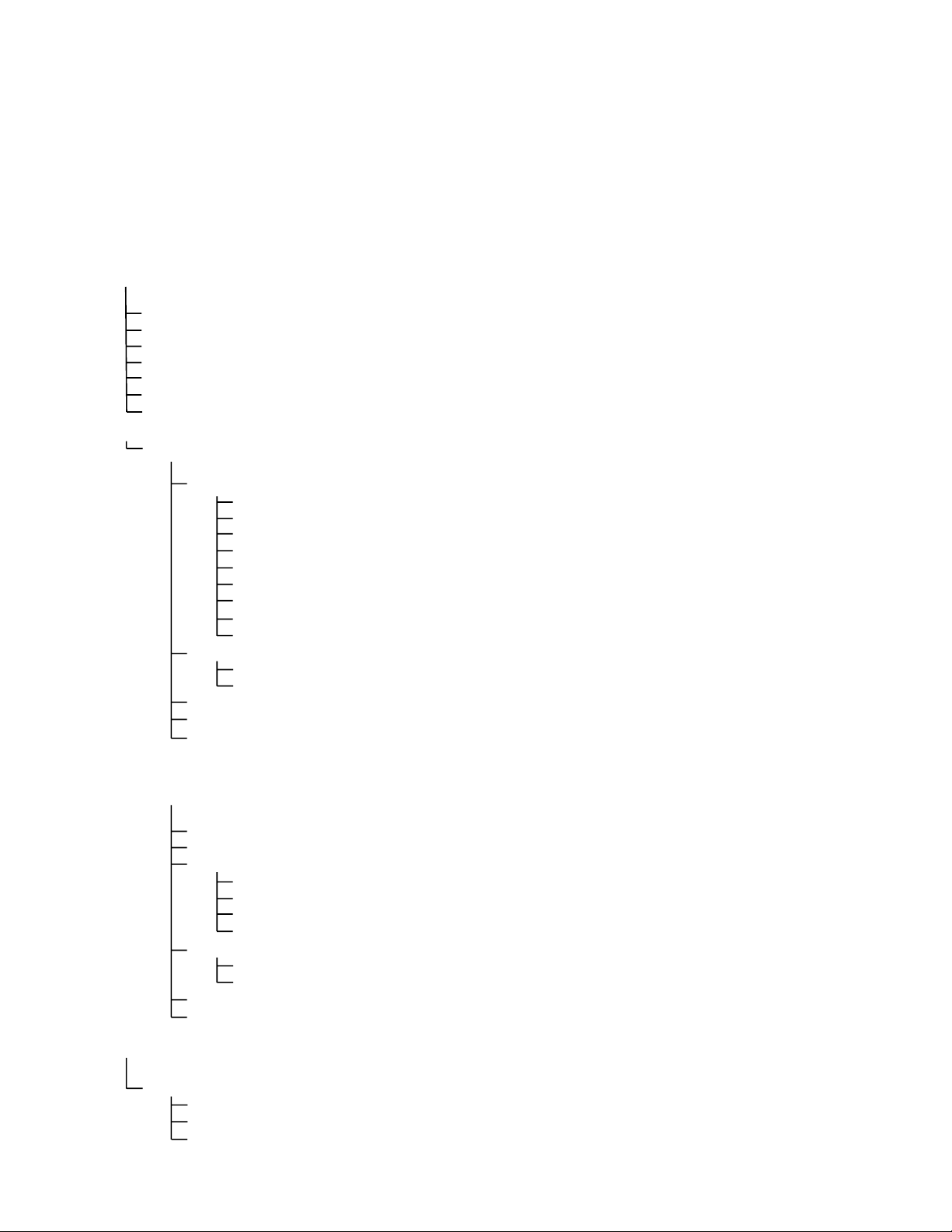
M3000 Menu Summary Tree
Reflected below are the major programming sections in the M3000 and the order in which submenu
headings will be found under the sections in the Installation and Operation Manual.
Adding New Product Menu Items (Product Selection) See section 4.10.2
Storing Product Menu Items in Product Buttons See section 4.10.3
Draining, Refilling, and Disposing of Oil See section 4.10.4
Filter Menu
[Press and hold ◄ FLTR or FLTR ►]
Programming
…………………………………………………………………………………………………… …….. 4.11
Auto Filter
Maint Filter
Dispose
Drain to Pan
Fill Vat from Drain Pan
Fill Vat from Bulk (Bulk Only)
Pan to Waste (Bulk Only)
Level 1 Program
[Press and hold TEMP and INFO buttons, 2 beeps, displays Level 1, enter 1234]
Product Selection
…….……………….....………………………………………………………….. 4.12
..…….....………………………………………………………….. 4.10.2
Name
Cook Time
Temp
Cook ID
Duty Time 1
Duty Time 2
Qual Tmr
AIF Disable
Assign Btn
AIF Clock
..………………………………………………………………………………… 4.12.1
Disabled
Enabled
Deep Clean Mode
High-Limit Test
Fryer Setup
……..……………………...…………………………………….. 4.12.2
…………….…………………….…………………………………….. 4.12.3
…………………….……………………………………………………………….. 4.9
Level 2 Program (Manager Level)
[Press and hold TEMP and INFO buttons, 3 beeps, displays Level 2, enter 1234]
Prod Comp
E-Log
Password Setup
Alert Tone Volume and Tone
Filter After
Filter Time
Info Mode
………………...………………………...………………………………………..…………… ………….. 4.14
[Press and hold INFO for 3 seconds, displays Info Mode]
Full/Split Vat Configuration
Filter Stats
Review Usage
Last Load
Sensitivity for product
Log of last 10 error codes
Change passwords
Setup [enter 1234]
Usage [enter 4321]
Level 1 [enter 1234]
Level 2 [enter 1234]
Volume 1-9
Tone 1-3
Sets number of cooks before filter prompt
Sets amount of time between filter cycles
..……………….……………………………………………………………….. 4.14.1
………….……………………………………………………………….. 4.14.2
………………….……………………………………………………………….. 4.14.3
……………………………………………….. 4.13
…………………………………….. 4.13.1
…………………………….. 4.13.2
……………………………… 4.13.3
...………………………………………….. 4.13.4
………….. 4.13.5
………….. 4.13.6

LOV™ ELECTRIC WARRANTY STATEMENT
Frymaster, L.L.C. makes the following limited warranties to the original purchaser only for this
equipment and replacement parts:
A. WARRANTY PROVISIONS - FRYERS
1. Frymaster L.L.C. warrants all components against defects in material and workmanship for a
period of two years.
2. All parts, with the exception of the frypot, O-rings and fuses, are warranted for two years
after installation date of fryer.
3. If any parts, except fuses and filter O-rings, become defective during the first two years after
installation date, Frymaster will also pay straight-time labor costs up to two hours to replace
the part, plus up to 100 miles/160 km of travel (50 miles/80 km each way).
B. WARRANTY PROVISIONS - FRYPOTS
The frypot has a lifetime parts and labor warranty. If a frypot develops a leak after installation,
Frymaster will replace the frypot, allowing up to the maximum time per the Frymaster time
allowance chart hours of straight-time labor. Components attached to the frypot, such as the
high-limit, probe, gaskets, seals, and related fasteners, are also covered by the lifetime warranty
if replacement is necessitated by the frypot replacement. Leaks due to abuse or from threaded
fittings such as probes, sensors, high-limits, drain valves or return piping are not included.
C. PARTS RETURN
All defective in-warranty parts must be returned to a Frymaster Authorized Service Agency
within 60 days for credit. After 60 days, no credit will be allowed.
D. WARRANTY EXCLUSIONS
This warranty does not cover equipment that has been damaged due to misuse, abuse, alteration,
or accident such as:
• improper or unauthorized repair (including any frypot which is welded in the field);
• failure to follow proper installation instructions and/or scheduled maintenance procedures as
prescribed in your MRC cards. Proof of scheduled maintenance is required to maintain the
warranty;
• improper maintenance;
• damage in shipment;
• abnormal use;
• removal, alteration, or obliteration of either the rating plate or the date code on the heating
elements;
• operating the frypot without shortening or other liquid in the frypot;
i

• no fryer will be warranted under the ten-year program for which a proper start-up form has not
been received.
This warranty also does not cover:
• transportation or travel over 100 miles/160 km (50 miles/80 km each way), or travel over two
hours;
• overtime or holiday charges;
• consequential damages (the cost of repairing or replacing other property which is damaged), loss
of time, profits, use or any other incidental damages of any kind.
There are no implied warranties of merchantability or fitness for any particular use or purpose.
This warranty is applicable at the time of this printing and is subject to change.
ii
BIELA14 SERIES GEN II LOV™ ELECTRIC FRYER
CHAPTER 1: INTRODUCTION
NOTE: The Frymaster BIELA14 fryer requires a start-up, demonstration and training
before normal restaurant operations can begin.
1.1 General
Read the instructions in this manual thoroughly before attempting to operate this equipment. This
manual covers all configurations of McDonald’s BIELA14 LOV™ models. The fryers in this model
family have most parts in common, and when discussed as a group, will be referred to as “LOV™
fryers.
Although similar in appearance to the RE14 McDonald’s electric fryers, the BIELA14 fryers feature
a low oil volume frypot, automatic oil top off and an automatic intermittent filtration unit. The
Euro-Look design incorporates a rounded topcap and a large round drain, which ensures that fries
and other debris, will be washed into the filter pan. The BIELA14 LOV™ fryers are controlled with
an M3000 computer. Fryers in this series come in full- or split-vat arrangements, and can be
purchased in batteries of up to five fryers.
1.2 Safety Information
Before attempting to operate your unit, read the instructions in this manual thoroughly.
Throughout this manual, you will find notations enclosed in double-bordered boxes similar to the
one below.
DANGER
Hot oil causes severe burns. Never attempt to move a fryer containing hot oil or to
transfer hot oil from one container to another.
CAUTION boxes contain information about actions or conditions that may cause or result in a
malfunction of your system.
WARNING boxes contain information about actions or conditions that may cause or result in
damage to your system, and which may cause your system to malfunction.
DANGER boxes contain information about actions or conditions that may cause or result in
injury to personnel, and which may cause damage to your system and/or cause your system to
malfunction.
The BIELA14 LOV™ fryers incorporate a high-temperature detection feature which shuts off power
to the elements should the temperature controls fail.
1-1
1.3 Computer Information for the M3000 Computers
This equipment has been tested and found to comply with the limits for a Class A digital device,
pursuant to Part 15 of the FCC rules. While this device is a verified Class A device, it has been
shown to meet the Class B limits. These limits are designed to provide reasonable protection against
harmful interference when the equipment is operated in a commercial environment. This equipment
generates, uses and can radiate radio frequency energy and, if not installed and used in accordance
with the instruction manual, may cause harmful interference to radio communications. Operation of
the equipment in a residential area is likely to cause harmful interference in which case the user will
be required to correct the interference at their own expense.
The user is cautioned that any changes or modifications not expressly approved by the party
responsible for compliance could void the user's authority to operate the equipment.
If necessary, the user should consult the dealer or an experienced radio and television technician for
additional suggestions.
The user may find the following booklet prepared by the Federal Communications Commission
helpful: "How to Identify and Resolve Radio-TV Interference Problems". This booklet is available
from the U.S. Government Printing Office, Washington, DC 20402, Stock No. 004-000-00345-4.
1.4 European Community (CE) Specific Information
The European Community (CE) has established certain specific standards regarding equipment of
this type. Whenever a difference exists between CE and non-CE standards, the information or
instructions concerned are identified by means of shadowed boxes similar to the one below.
CE Standard
Example of box used to distinguish CE and
Non-CE specific information.
1.5 Installation, Operating, and Service Personnel
Operating information for Frymaster equipment has been prepared for use by qualified and/or
authorized personnel only, as defined in Section 1.6. All installation and service on Frymaster
equipment must be performed by qualified, certified, licensed, and/or authorized installation
or service personnel, as defined in Section 1.6.
1.6 Definitions
QUALIFIED AND/OR AUTHORIZED OPERATING PERSONNEL
Qualified/authorized operating personnel are those who have carefully read the information in this
manual and have familiarized themselves with the equipment functions, or who have had previous
experience with the operation of the equipment covered in this manual.
1-2

QUALIFIED INSTALLATION PERSONNEL
Qualified installation personnel are individuals, firms, corporations, and/or companies which, either
in person or through a representative, are engaged in and are responsible for the installation of
electrical appliances. Qualified personnel must be experienced in such work, be familiar with all
electrical precautions involved, and have complied with all requirements of applicable national and
local codes.
QUALIFIED SERVICE PERSONNEL
Qualified service personnel are those who are familiar with Frymaster equipment and who have been
authorized by Frymaster, L.L.C. to perform service on the equipment. All authorized service
personnel are required to be equipped with a complete set of service and parts manuals, and to stock
a minimum amount of parts for Frymaster equipment. A list of Frymaster Factory Authorized
Servicers (FAS’s) is located on the Frymaster website at www.frymaster.com. Failure to use
qualified service personnel will void the Frymaster warranty on your equipment
1.7 Shipping Damage Claim Procedure
What to do if your equipment arrives damaged:
Please note that this equipment was carefully inspected and packed by skilled personnel before
leaving the factory. The freight company assumes full responsibility for safe delivery upon
acceptance of the equipment.
1. File Claim for Damages Immediately - regardless of extent of damage.
2. Inspect For and Record All Visible Loss or Damage, and ensure that this information is noted
on the freight bill or express receipt and is signed by the person making the delivery.
3. Concealed Loss or Damage- If damage is unnoticed until equipment is unpacked, notify the
freight company or carrier immediately upon discovery and file a concealed damage claim.
This must be submitted within 15 days of date of delivery. Be sure to retain container for
inspection.
Frymaster
DOES NOT ASSUME RESPONSIBILITY FOR DAMAGE OR LOSS
INCURRED IN TRANSIT.
1-3

1.8 Service Information
For non-routine maintenance or repairs, or for service information, contact your local Frymaster
Authorized Service Agency (ASA). In order to assist you quickly, the Frymaster Authorized Service
Agency (ASA) or Service Department representative requires certain information about your
equipment. Most of this information is printed on a data plate affixed to the inside of the fryer door.
Part numbers are found in the Service and Parts Manual. Parts orders may be placed directly with
your local ASA or distributor. Included with fryers when shipped from the factory is a list of
Frymaster ASA’s. If you do not have access to this list, contact the Frymaster Service Department at
1-800-551-8633 or 1-318-865-1711 or by email at service@frymaster.com.
The following information will be needed in order to assist you efficiently:
Model Number _________________________
Serial Number__________________________
Voltage _______________________________
Nature of the Problem____________________
_____________________________________
_____________________________________
RETAIN AND STORE THIS MANUAL IN A SAFE PLACE FOR FUTURE USE.
1-4
BIELA14 SERIES GEN II LOV™ ELECTRIC FRYER
CHAPTER 2: INSTALLATION INSTRUCTIONS
2.1 General Installation Requirements
Proper installation is essential for the safe, efficient, trouble-free operation of this appliance.
Qualified, licensed, and/or authorized installation or service personnel, as defined in Section
1.6 of this manual, should perform all installation and service on Frymaster equipment.
Failure to use qualified, licensed, and/or authorized installation or service personnel (as
defined in Section 1.6 of this manual) to install or otherwise service this equipment will void
the Frymaster warranty and may result in damage to the equipment or injury to personnel.
Where conflicts exist between instructions and information in this manual and local or
national codes or regulations, installation and operation shall comply with the codes or
regulations in force in the country in which the equipment is installed.
Service may be obtained by contacting your local Frymaster Authorized Service Agency.
NOTICE
All fryers shipped without factory supplied cords and plug assemblies must be
hardwired using flexible conduit to the terminal block located on the rear of the fryer.
These fryers should be wired to NEC specifications. Hardwired units must include
installation of restraint devices.
DANGER
Adequate means must be provided to limit the movement of this appliance without
depending on or transmitting stress to the electrical conduit. A restraint kit is
provided with the fryer. If the restraint kit is missing contact your local Frymaster
Authorized Service Agency (ASA).
NOTICE
If this equipment is wired directly into the electrical power supply, a means for
disconnection from the supply having a contact separation of at least 3-mm in all
poles must be incorporated in the fixed wiring.
NOTICE
This equipment must be positioned so that the plug is accessible unless other
means for disconnection from the power supply (e.g., a circuit breaker) is provided.
NOTICE
If this appliance is permanently connected to fixed wiring, it must be connected by
means of copper wires having a temperature rating of not less than 167°F (75°C).
2-1
NOTICE
If the electrical power supply cord is damaged, it must be replaced by a Frymaster
Authorized Service Agency technician or a similarly qualified person in order to
avoid a hazard.
DANGER
This appliance must be connected to a power supply having the same voltage and
phase as specified on the rating plate located on the inside of the appliance door.
DANGER
All wiring connections for this appliance must be made in accordance with the
wiring diagram(s) furnished with the appliance. Refer to the wiring diagram(s)
affixed to the inside of the appliance door when installing or servicing this
equipment.
DANGER
Do not attach an apron drainboard to a single fryer. The fryer may become unstable,
tip over, and cause injury. The appliance area must be kept free and clear of
combustible material at all times.
DANGER
Building codes prohibit a fryer with its open tank of hot oil being installed beside an
open flame of any type, including those of broilers and ranges.
In the event of a power failure, the fryer(s) will automatically shut down. If this occurs, turn the
power switch OFF. Do not attempt to start the fryer(s) until power is restored.
This appliance must be kept free and clear of combustible material, except that it may be installed on
combustible floors.
A clearance of 6 inches (15cm) must be provided at both sides and back adjacent to combustible
construction. A minimum of 24 inches (61cm) should be provided at the front of the equipment for
servicing and proper operation.
WARNING
Do not block the area around the base or under the fryers.
2.1.2 Electrical Grounding Requirements
All electrically operated appliances must be grounded in accordance with all applicable national and
local codes, and, where applicable, CE codes. All units (cord connected or permanently connected)
should be connected to a grounded power supply system. A wiring diagram is located on the inside
of the fryer door. Refer to the rating plate on the inside of the fryer door for proper voltages.
WARNING
To ensure the safe and efficient operation of the fryer and hood, the electrical plug
for the control power, which powers the hood, must be fully engaged and locked in
its pin and sleeve socket.
2-2
2.1.3 Australian Requirements
To be installed in accordance with AS 5601 / AG 601, local authority, gas, electricity, and any other
relevant statutory regulations.
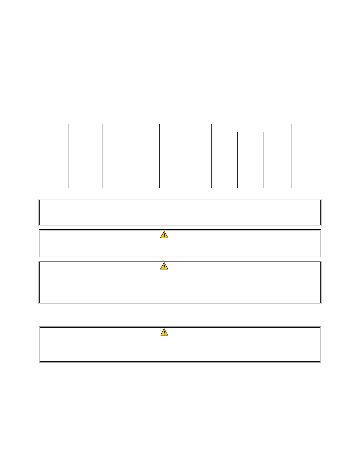
2.2 Power Requirements
The three phase supply plug for the elements is rated at 60 amps, 250 VAC and is NEMA
configuration L15-60P. The control and filter plug is rated at 20 amps, 120/208 VAC and is NEMA
configuration L21-20P. Each fryer should have its cord for the element supply on an individual
circuit as well as the control cord.
WIRE
VOLTAGE PHASE
208 3 3 6 (16) 39 39 39
240 3 3 6 (16) 34 34 34
480 3 3 8 (10) 17 17 17
220/380 3 4 6 (16) 21 21 21
240/415 3 4 6 (16) 20 20 21
230/400 3 4 6 (16) 21 21 21
SERVICE
MIN.
SIZE
AWG
(mm2)
AMPS PER LEG
L1 L2 L3
NOTICE
If this appliance is permanently connected to fixed wiring, it must be connected by
means of copper wires having a temperature rating of not less than 167°F (75°C).
DANGER
This appliance must be connected to a power supply having the same voltage and
phase as specified on the rating plate located on the inside of the appliance door.
DANGER
All wiring connections for this appliance must be made in accordance with the
wiring diagram(s) furnished with the appliance. Refer to the wiring diagram(s)
affixed to the inside of the appliance door when installing or servicing this
equipment.
2.3 After Fryers Are Positioned At the Frying Station
DANGER
No structural material on the fryer should be altered or removed to accommodate
placement of the fryer under a hood. Questions? Call the Frymaster Service Hotline
at 1-800-551-8633.
1. Once the fryer has been positioned at the frying station, use a carpenter’s level placed across the
top of the frypot to verify that the unit is level, both side-to-side and front-to-back.
To level fryers, adjust the casters being careful to ensure the fryer(s) are at the proper height in
the frying station.
2-3
When the fryer is leveled in its final position, install the restraints provided by the KES to limit
its movement so that it does not depend on or transmit stress to the electrical conduit or
connection. Install the restraints in accordance with the provided instructions. If the restraints are
disconnected for service or other reasons, they must be reconnected before the fryer is used.
DANGER
Adequate means must be provided to limit the movement of this appliance without
depending on or transmitting stress to the electrical conduit. A restraint kit is
provided with the fryer. If the restraint kit is missing contact your local Frymaster
Authorized Service Agency (ASA).
DANGER
Hot oil can cause severe burns. Avoid contact. Under all circumstances, oil must be
removed from the fryer before attempting to move it to avoid spills, falls, and severe
burns. Fryers may tip and cause personal injury if not secured in a stationary
position.
2. Clean and fill frypot(s) to the bottom oil level line with cooking oil. (See Equipment Setup and
Shutdown Procedures in Chapter 3.)
2-4
BIELA14 SERIES GEN II LOV™ ELECTRIC FRYER
CHAPTER 3: OPERATING INSTRUCTIONS
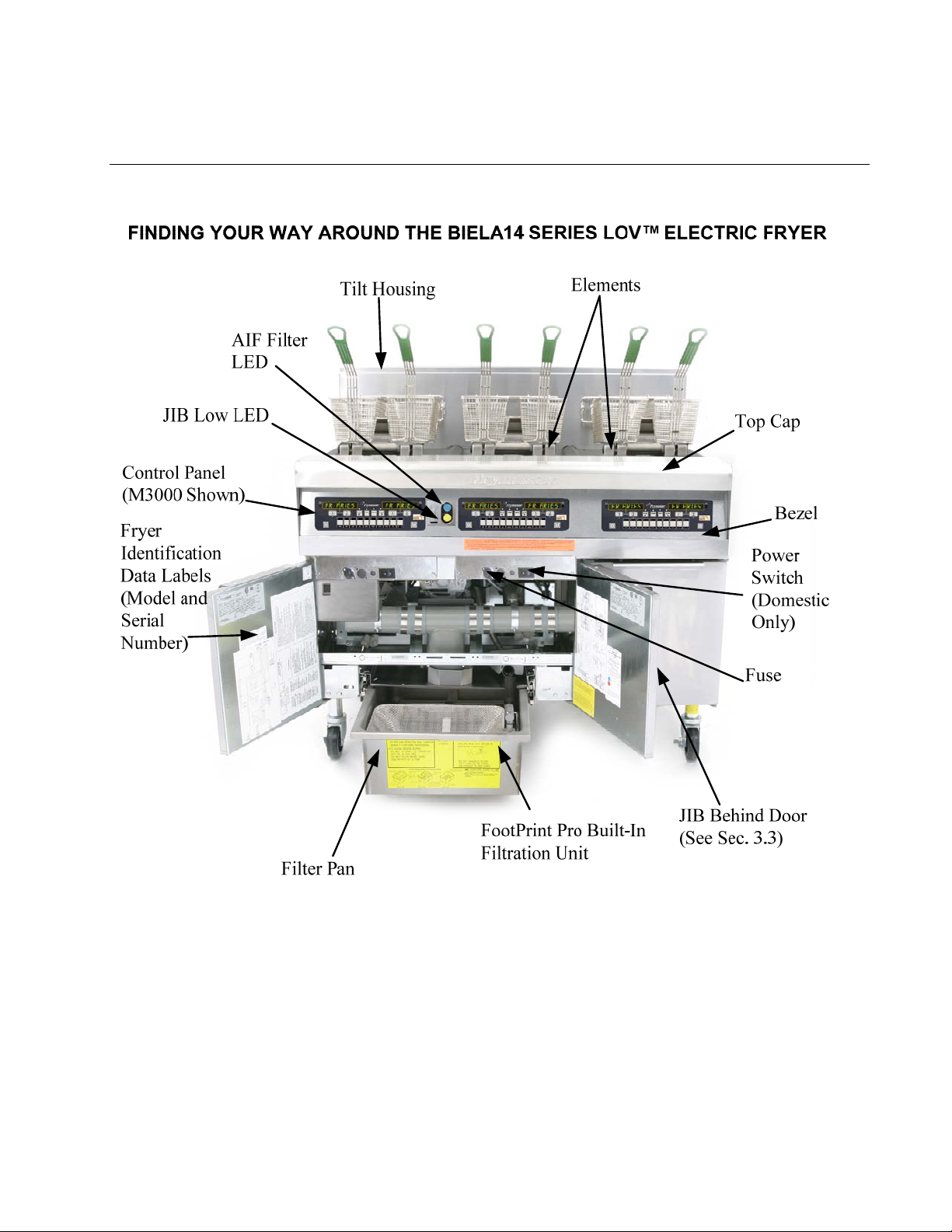
TYPICAL CONFIGURATION (BIELA314 SHOWN)
NOTE: The appearance of your fryer may differ slightly from that
shown depending upon configuration and date of manufacture.
3–1
3.1 Equipment Setup and Shutdown Procedures
Setup
DANGER
Never operate the appliance with an empty frypot. The frypot must be filled to the fill line
with water or oil before energizing the elements. Failure to do so will result in irreparable
damage to the elements and may cause a fire.
DANGER
Remove all drops of water from the frypot before filling with oil. Failure to do so will cause
spattering of hot liquid when the oil is heated to cooking temperature.
WARNING
The BIELA14 is not intended to use solid shortening. Use only liquid shortening with this
fryer. The use of solid shortening will clog the oil lines. The oil capacity of the BIELA14
fryer is 31 lbs. (3.7 gallons/14 liters) for a full-vat and 15.5 lbs. (2.5 gallons/7 liters) for a dualvat at 70°F (21°C).
1. Fill the frypot with cooking oil to the bottom OIL LEVEL line located on the rear of the frypot. This will
allow for oil expansion as heat is applied. Do not fill cold oil any higher than the bottom line; overflow
may occur as heat expands the oil. For bulk oil systems see Section 4.11.4 on page 4-22 for instructions
to fill the vat from bulk.
2. Ensure that the power cord(s) is/are plugged and locked (if applicable) into the appropriate receptacle(s).
Verify that the face of the plug is flush with the outlet plate, with no portion of the prongs visible.
3. Ensure that the power is switched on. Some models are equipped with a master switch located behind the
fryer door cabinet on the front panel of the component box, next to the fuse.
4. Ensure that the computer is switched ON. When the computer is switched on, the fryer will begin
heating and will display MLT-CYCL alternating with LOW TEMP until the fryer temperature reaches
180°F (82°C). LOW TEMP is displayed until within 15° of setpoint. Once the fryer reaches setpoint,
the computer display changes to the product or dashed lines and the fryer is ready for use.
5. Ensure that the oil level is at the top OIL LEVEL line when the oil is at its cooking temperature
Shutdown
1. Turn the fryer off.
2. Filter the oil and clean the fryers (See Chapters 5 and 6).
.
3. Place the frypot covers on the frypots.
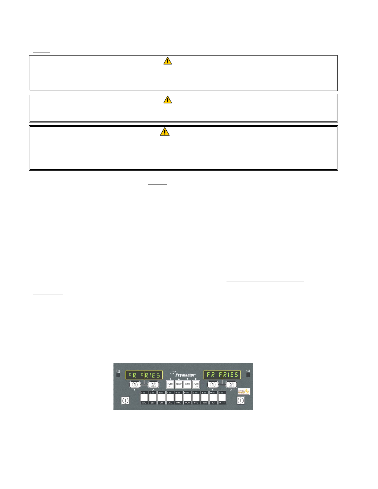
3.2 Operation
This fryer is equipped with M3000 computers (illustrated below). Refer to the M3000 Computer Operating
Instructions in Chapter 4 for the computer programming and operating procedures.
M3000 COMPUTER
Refer to Chapter 5 of this manual for operating instructions for the built-in filtration system.
3–2
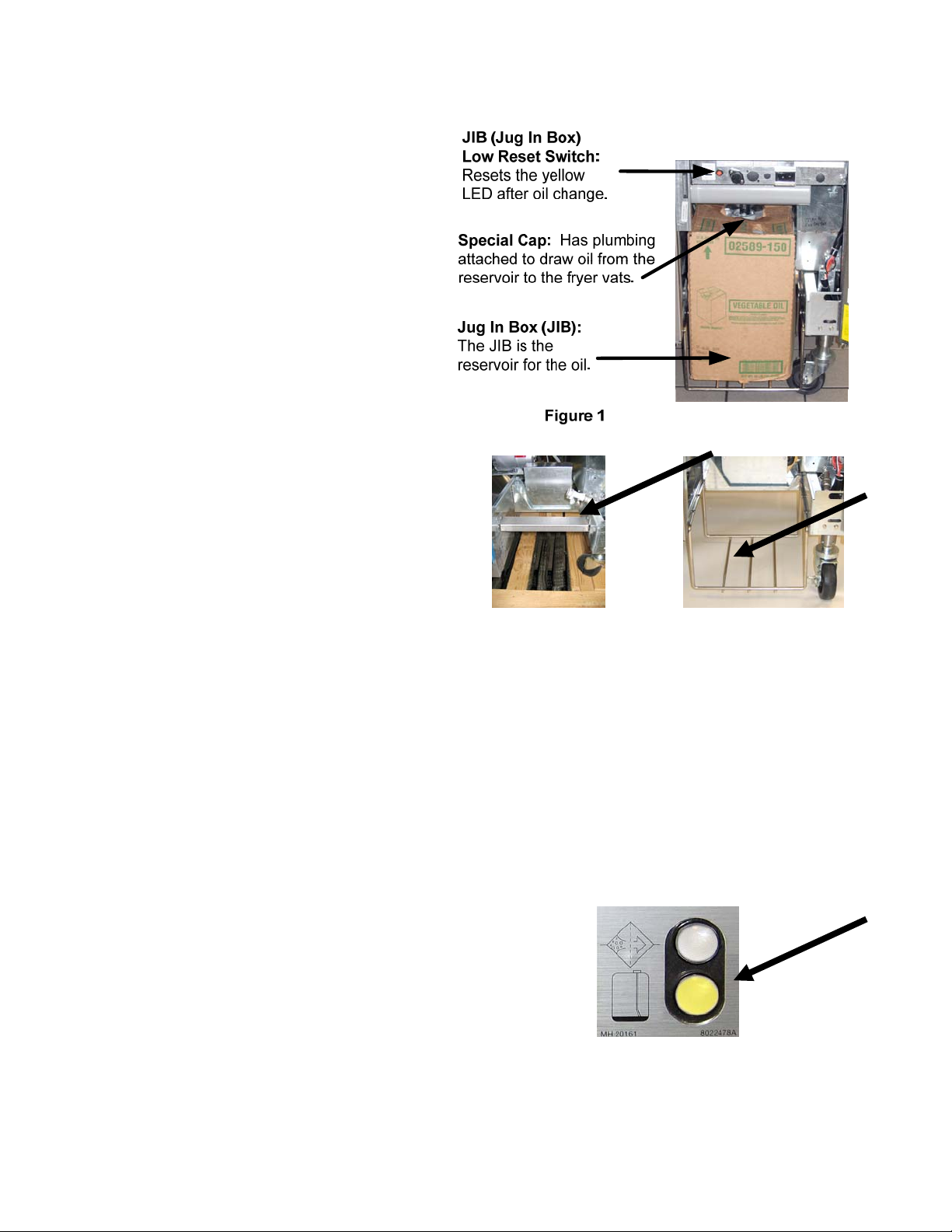
3.3 Low Oil Volume Automatic Refill
When the Low Oil Volume (LOV™)
system is in place on the fryer, the frypot
oil levels are continually checked and
topped off as necessary from a reservoir in
the cabinet. The reservoir holds a 35
pound box of oil. In a typical operation
this will last approximately two days.
Components of the system are annotated
at the right (see Figure 1).
NOTE: The system is intended to top
off the frypots, not fill them. The frypots
will require manual filling upon startup
and after deep clean (boil-out).
3.3.1 Prepare the System for Use
To prepare the system for its initial
operation, remove cross brace (see Figure
2). Using the screws removed from the
cross brace, attach the JIB basket shipped
in the accessories pack (see Figure 3). If
using the solid shortening option see
Appendix B.
Figure 2 Figure 3
3.3.2 Install the Oil Reservoir
Remove the original lid from the oil container and foil liner. Replace with the provided cap, which has
connected suction hardware. Ensure the feeder tube from the cap reaches to the bottom of the oil
container.
Place the oil container inside the cabinet and slide it into place (as shown on the following page).
Avoid catching the suction hardware on the cabinet interior as the container is placed in the fryer.
The system is now ready for operation.
3.3.3 Routine Oil Changes
When the oil reservoir level is low, an
orange LED is activated (see Figure 4).
Once the reservoir is refilled and/or
replaced, press and hold the orange reset
button above the JIB until the orange LED
is no longer illuminated. If using solid
shortening see Appendix C for
instructions.
Figure 4
3–3
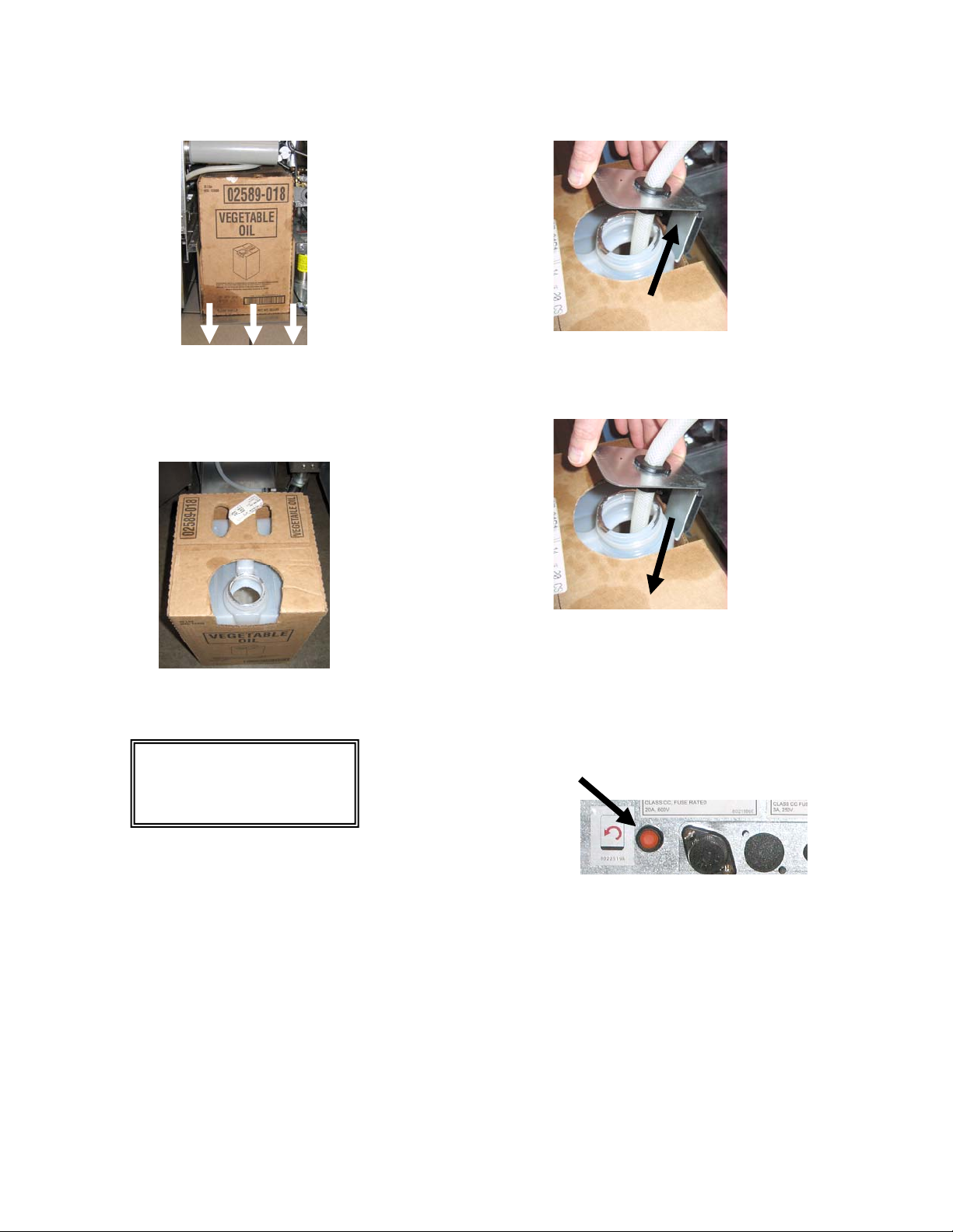
1. Open the cabinet and slide the JIB
from the cabinet (see Figure 5).
2. Remove the cap and pour any remaining oil in the
container into all fry vats equally (see Figure 6).
Figure 5
Figure 6
3. With the replacement jug upright
remove the cap and foil seal (see
4. Put the tube in the new full container (see Figure 8).
Figure 7).
Figure 8
Figure 7
5. Slide the JIB onto the shelf inside the fryer cabinet (as
seen in Figure 5).
6. Press and hold the orange JIB reset switch until the
orange JIB LED is no longer illuminated (see Figure
WARNING:
Do not add HOT or
USED oil to a JIB.
9).
Figure 9
3.3.4 Bulk Oil Systems
Instructions for installing and using bulk oil systems are found in Appendix A located
at the rear of this manual.
3–4

BIELA14 SERIES GEN II LOV™ ELECTRIC FRYER
ON/OFF
Cook Channel
and Selection
Buttons
ON/OFF
CHAPTER 4: M3000 COMPUTER INSTRUCTIONS
Filter, Temp, Info,
Programming and
Navigation Buttons
FR FRIES
Product Buttons
FR FRIES
4.1 M3000 General Information
Welcome to the M3000, a computer that retains the one-button ease of the M2000 and 100B and the
utility of 40-product menu capability. The computer is easy to use. One button push starts a cook
cycle for an item cooked in a dedicated vat. The same flexible computer on a multi-product vat
requires only two button pushes to
launch a cook cycle. Just choose a
menu item on a product button and
press, and then press a cook channel
button under the display showing
the desired item. The computer can
move seamlessly from McNuggets
to Crispy Chicken to any added
menu item.
Pressing product buttons 3 or 9 displays McChick.
In a typical store setting, the
M3000s on the three-vat fry station
display FR FRIES (shown above)
and will launch a cook cycle with
one push of a cook channel button.
On the chicken/filet station, the
LED display shows dashed lines.
To launch a cook cycle, press a
product button and then press the
cook channel button that
Pressing either cook cycle button under the McChick
displays launches a cook cycle.
corresponds with the location of the
dropped basket. By pressing the product button for McChicken, McChick will appear in the display.
Just press the cook channel button corresponding to the location of the appropriate dropped basket.
The M3000 will operate with electric and gas fryers, both full- and split-vat.
Heat
Indicator
Lamp
4-1
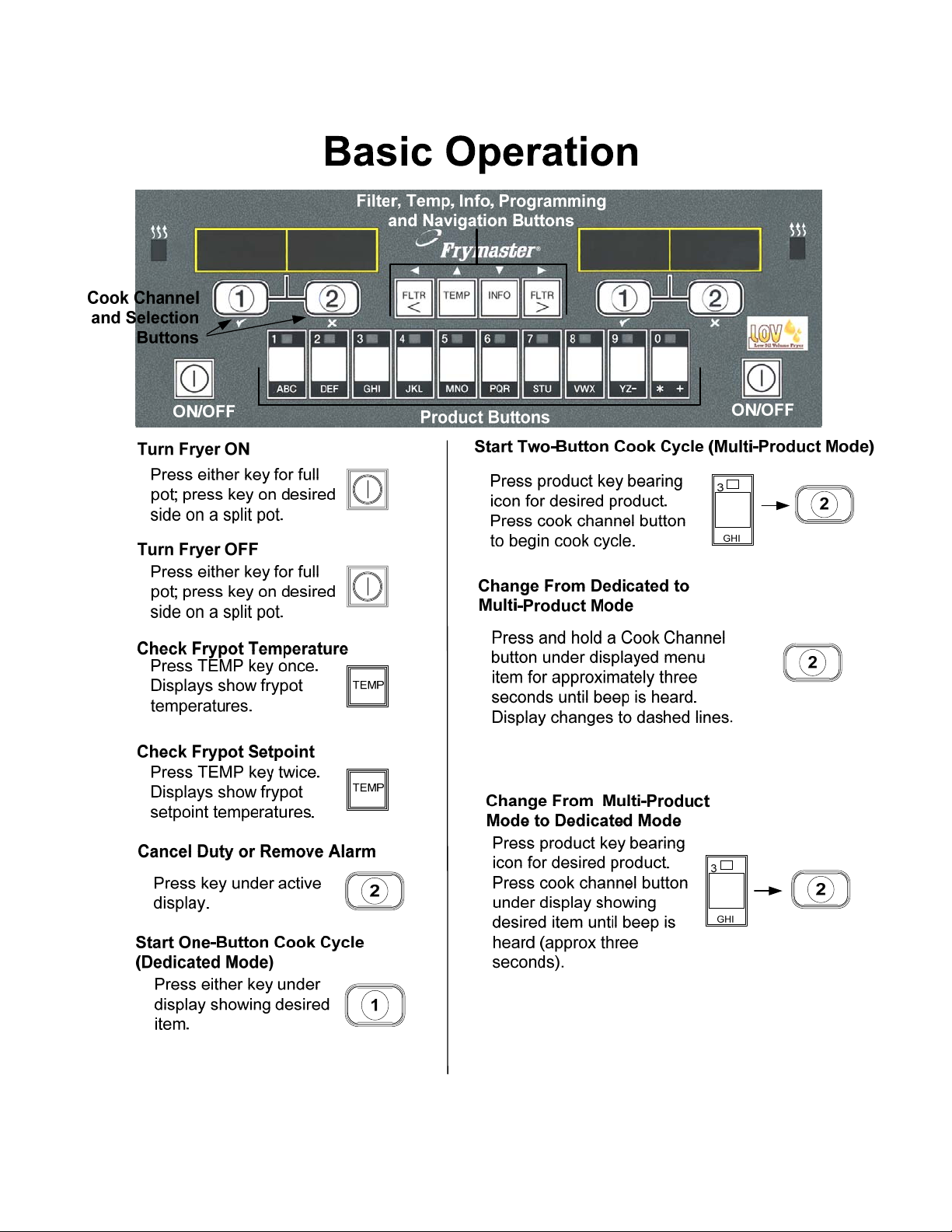
4.2 Basic Operation
4-2
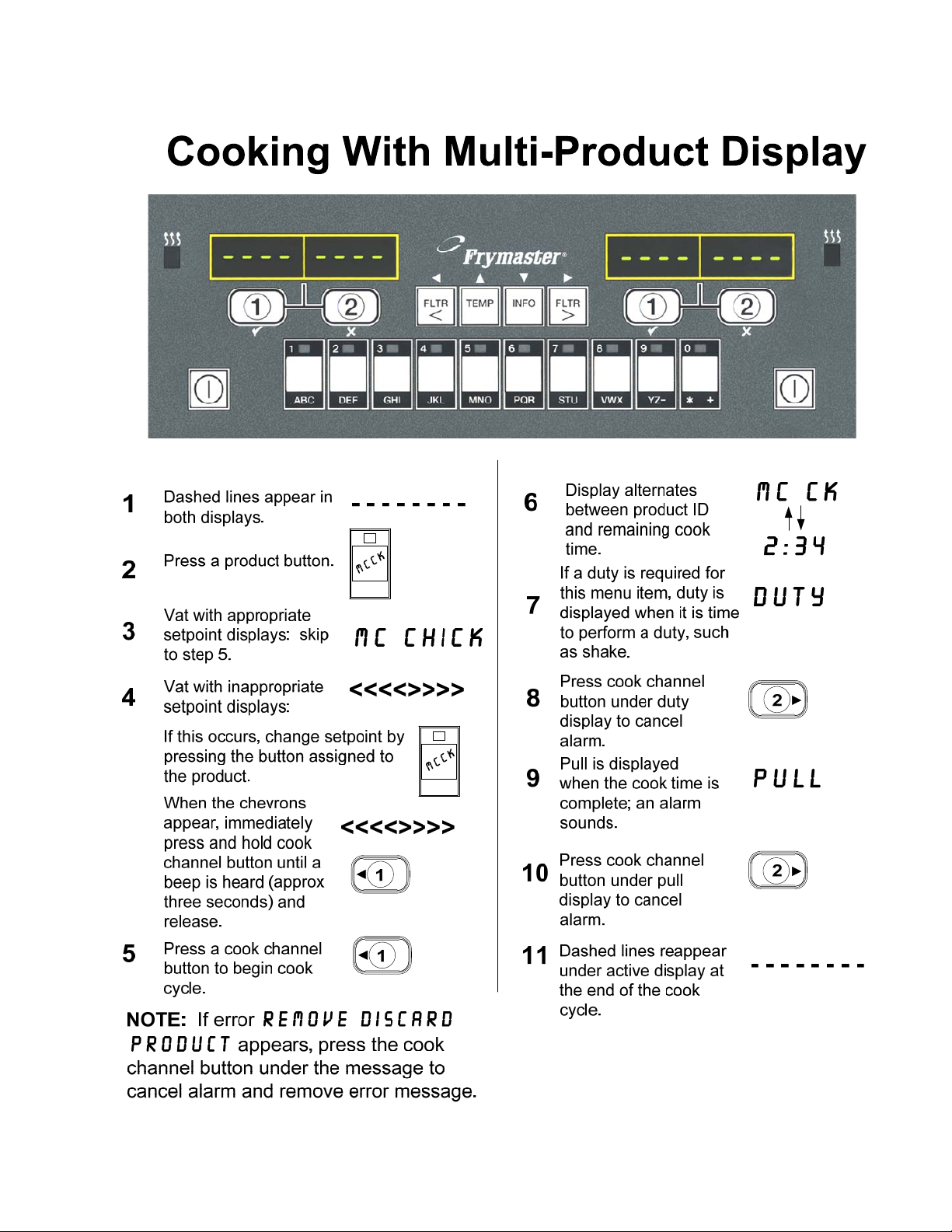
4.3 Cooking with Multi-Product Display
4-3
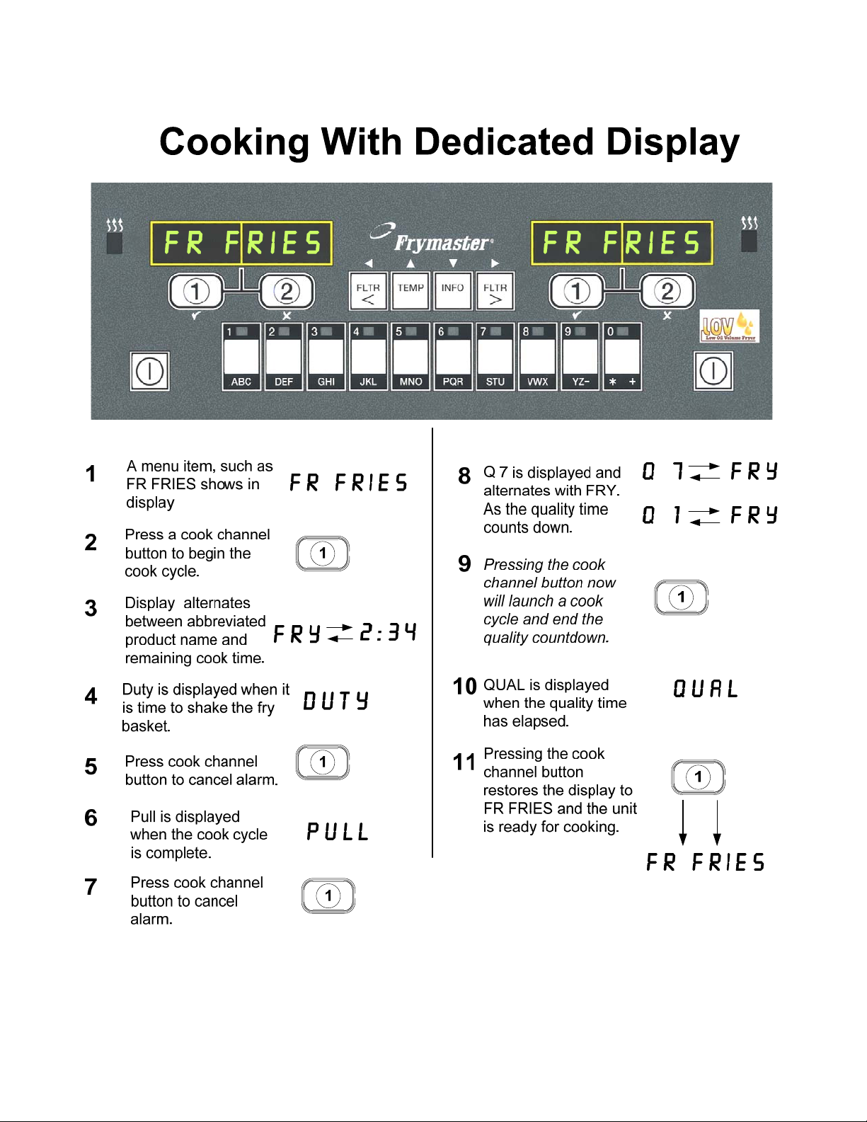
4.4 Cooking with Dedicated Display
4-4
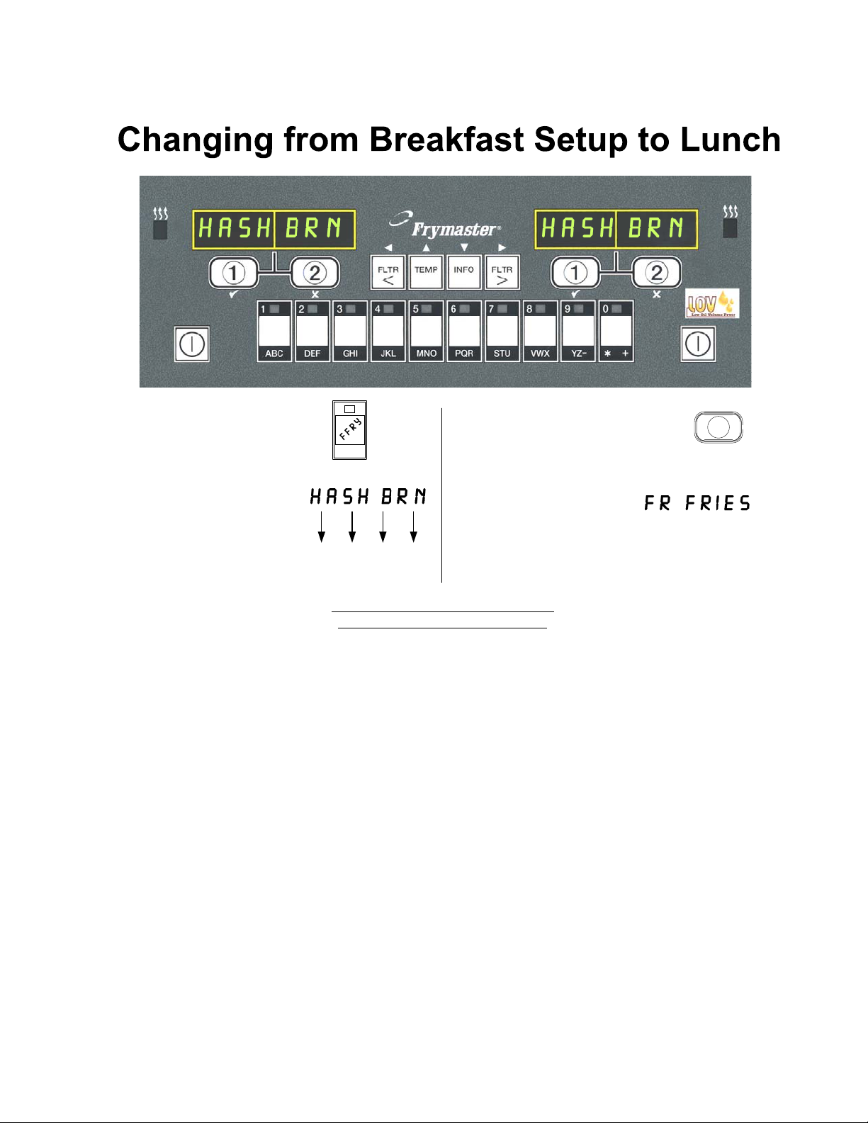
4.5 Changing from Breakfast Setup to Lunch
Press and quickly
1
release product button
for french fries.
Computer will change
from HASH BRN to
2
<<<< >>>>; an alarm
will sound.
1
ABC
Press and hold the cook
3
channel button under the
display until a beep is heard
(approximately three seconds)
and release.
Display changes to FR
4
FRIES.
1
<<<< >>>>
Perform these steps on both sides to
change both displays to FR FRIES
4-5
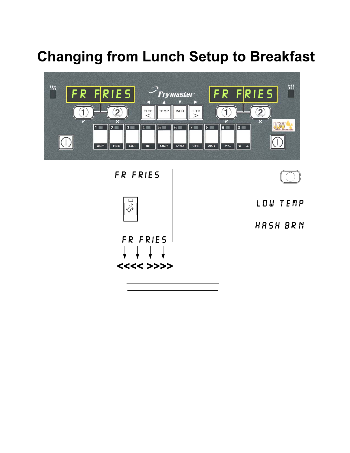
4.6 Changing from Lunch Setup to Breakfast
1
Computer displays
Press and quickly
2
release product button
for hash browns.
Computer display will
3
change from FR
FRIES to <<<< >>>>;
an alarm sounds.
Perform these steps on both sides to
change both displays to HASH BRN
Press and hold the cook channel
4
button under the display until a
beep is heard (approximately
three seconds) and release.
Display changes to LOW
5
TEMP until setpoint is
reached.
Display changes to
6
Hash Brn.
1
4-6
4.7 M3000 Button Description and Functions
4.7.1 Navigation Buttons
The menu on the M3000 uses 34and tu buttons to
navigate the various menus and submenus.
When programming, the left screen shows a menu or
submenu item. The right screen is for data entry. Data is
entered with alpha-numeric characters, scrolling through
lists or by toggling between choices.
During programming if a button is not pushed within one minute, the computer returns to operation
mode.
Left Display Right Display
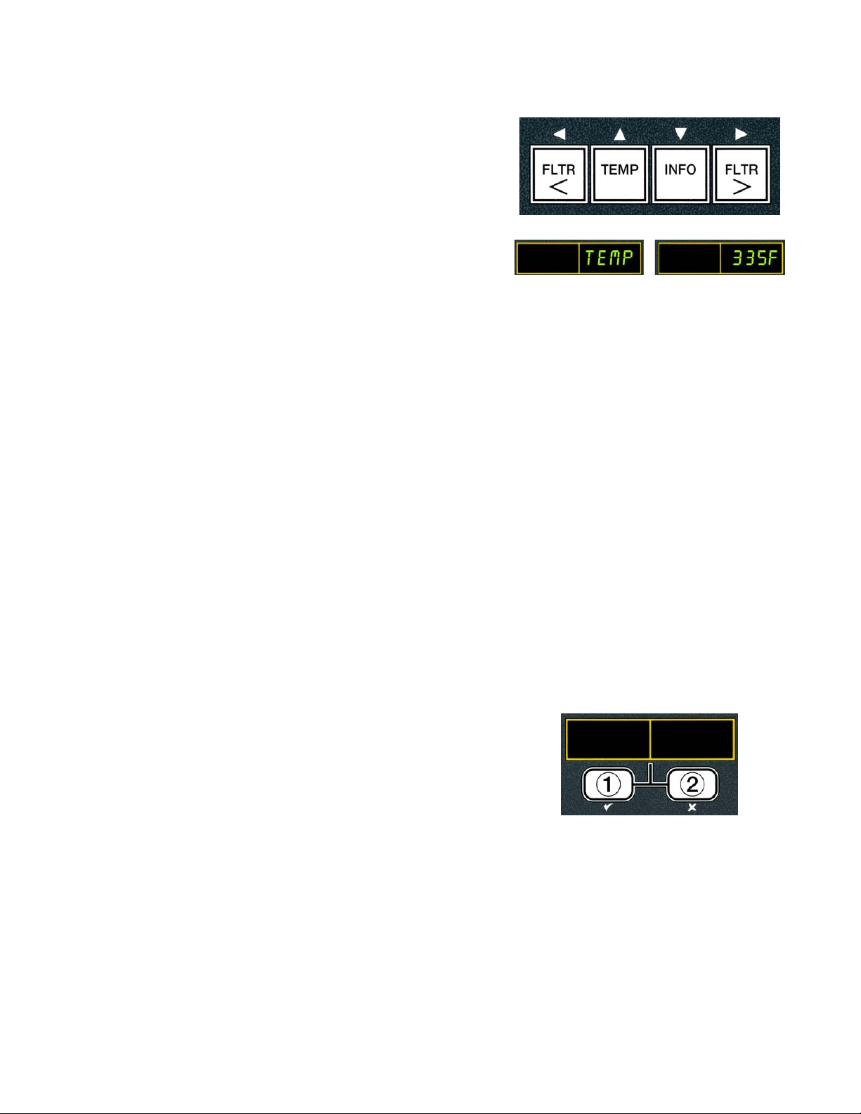
4.7.2 Filter, Temperature and Info Buttons
The < FLTR and FLTR > buttons (see Figure 1) are used to filter the left and right vats of a split
vat or a full vat fryer on demand. The FLTR buttons, if pressed once displays the number of cook
cycles remaining until a filtration prompt. When the FLTR button is pressed twice, the date and
time of the last filter is displayed. The TEMP button, if pressed once while the fryer is on,
displays current vat temperature on both sides. If the TEMP button is pressed twice while the fryer
is on, it shows the setpoint temperatures of the vats. If the fryer is off, the display shows the current
versions of software. The INFO button (see Figure 1), if pressed once when the fryer is on, shows
the recovery time for each vat from the last test. Recovery is the time required for the fryer to raise
the temperature of the oil 50°F (28°C) between 250°F (121°C) and 300°F (149°C). Maximum
recovery time should not exceed 1:40 for electric or 2:25 for gas. If the INFO button is pressed and
held for three seconds it shows information such as usage, filter statistics and last cook cycles (see
page 4-34 for more details on the INFO button).
4.7.3 Cook Channel and Selection Buttons
buttons are dual-function buttons shared with
The
the number 1 and 2 buttons. They are located directly
below the LED displays. Use these buttons to select or
cancel functions. The button is used to back out of and
exit submenus.
4-7

4.8 M3000 Menu Summary Tree
Reflected below are the major programming sections in the M3000 and the order in which submenu headings will be
found under the sections in the Installation and Operation Manual.
Adding New Product Menu Items (Product Selection) See section 4.10.2
Storing Product Menu Items in Product Buttons See section 4.10.3
Draining, Refilling, and Disposing of Oil See section 4.10.4
Filter Menu
[Press and hold ◄ FLTR or FLTR ►]
Programming
………………………………………………………………………………………………………….. 4.11
Auto Filter
Maint Filter
Dispose
Drain to Pan
Fill Vat from Drain Pan
Fill Vat from Bulk (Bulk Only)
Pan to Waste (Bulk Only)
Level 1 Program
[Press and hold TEMP and INFO buttons, 2 beeps, displays Level 1, enter 1234]
Product Selection
…….……………….....………………………………………………………….. 4.12
..…….....………………………………………………………….. 4.10.2
Name
Cook Time
Temp
Cook ID
Duty Time 1
Duty Time 2
Qual Tmr
AIF Disable
Assign Btn
AIF Clock
..………………………………………………………………………………… 4.12.1
Disabled
Enabled
Deep Clean Mode
High-Limit Test
Fryer Setup
……..……………………...…………………………………….. 4.12.2
…………….…………………….…………………………………….. 4.12.3
…………………….……………………………………………………………….. 4.9
Level 2 Program (Manager Level)
[Press and hold TEMP and INFO buttons, 3 beeps, displays Level 2, enter 1234]
Prod Comp
E-Log
Password Setup
Alert Tone Volume and Tone
Filter After
Filter Time
Info Mode
………………...………………………...………………………………………..……………………….. 4.14
[Press and hold INFO for 3 seconds, displays Info Mode]
Full/Split Vat Configuration
Filter Stats
Review Usage
Last Load
Sensitivity for product
Log of last 10 error codes
Change passwords
Setup [enter 1234]
Usage [enter 4321]
Level 1 [enter 1234]
Level 2 [enter 1234]
Volume 1-9
Tone 1-3
Sets number of cooks before filter prompt
Sets amount of time between filter cycles
..……………….……………………………………………………………….. 4.14.1
………….……………………………………………………………….. 4.14.2
………………….……………………………………………………………….. 4.14.3
……………………………………………….. 4.13
…………………………………….. 4.13.1
…………………………….. 4.13.2
……………………………… 4.13.3
...………………………………………….. 4.13.4
………….. 4.13.5
………….. 4.13.6
4-8
 Loading...