


& Service |
Series 45 |
Manual Parts |
Fryers Gas |
|
|
Frymaster, a member of the Commercial Food Equipment Service Association, recommends using CFESA Certified Technicians.
24-Hour Service Hotline 1-800-551-8633 |
NOVEMBER 2003 |
*8195665*
NOTICE
IF, DURING THE WARRANTY PERIOD, THE CUSTOMER USES A PART FOR THIS ENODIS EQUIPMENT OTHER THAN AN UNMODIFIED NEW OR RECYCLED PART PURCHASED DIRECTLY FROM FRYMASTER/DEAN, OR ANY OF ITS AUTHORIZED SERVICE CENTERS, AND/OR THE PART BEING USED IS MODIFIED FROM ITS ORIGINAL CONFIGURATION, THIS WARRANTY WILL BE VOID. FURTHER, FRYMASTER/DEAN AND ITS AFFILIATES WILL NOT BE LIABLE FOR ANY CLAIMS, DAMAGES OR EXPENSES INCURRED BY THE CUSTOMER WHICH ARISE DIRECTLY OR INDIRECTLY, IN WHOLE OR IN PART, DUE TO THE INSTALLATION OF ANY MODIFIED PART AND/OR PART RECEIVED FROM AN UNAUTHORIZED SERVICE CENTER.
NOTICE
This appliance is intended for professional use only and is to be operated by qualified personnel only. A Frymaster/DEAN Factory Authorized Service Center (FASC) or other qualified professional should perform installation, maintenance, and repairs. Installation, maintenance, or repairs by unqualified personnel may void the manufacturer’s warranty. See Chapter 1 of this manual for definitions of qualified personnel.
NOTICE
This equipment must be installed in accordance with the appropriate national and local codes of the country and/or region in which the appliance is installed. See NATIONAL CODE REQUIREMENTS in Chapter 2 of this manual for specifics.
NOTICE TO U.S. CUSTOMERS
This equipment is to be installed in compliance with the basic plumbing code of the Building Officials and Code Administrators International, Inc. (BOCA) and the Food Service Sanitation Manual of the U.S. Food and Drug Administration.
NOTICE
Drawings and photos used in this manual are intended to illustrate operational, cleaning and technical procedures and may not conform to onsite management operational procedures.
NOTICE TO OWNERS OF UNITS EQUIPPED WITH COMPUTERS
U.S.
This device complies with Part 15 of the FCC rules. Operation is subject to the following two conditions: 1) This device may not cause harmful interference, and 2) This device must accept any interference received, including interference that may cause undesired operation. While this device is a verified Class A device, it has been shown to meet the Class B limits.
CANADA
This digital apparatus does not exceed the Class A or B limits for radio noise emissions as set out by the ICES-003 standard of the Canadian Department of Communications.
Cet appareil numerique n’emet pas de bruits radioelectriques depassany les limites de classe A et B prescrites dans la norme NMB-003 edictee par le Ministre des Communcations du Canada.
 DANGER
Improper installation, adjustment, maintenance or service, and unauthorized alterations or modifications can cause property damage, injury, or death. Read the installation, operating, and service instructions thoroughly before installing or servicing this equipment. Only qualified service personnel may convert this appliance to use a gas other than that for which it was originally configured.
 DANGER
Adequate means must be provided to limit the movement of this appliance without depending upon the gas line connection. Single fryers equipped with legs must be stabilized by installing anchor straps. All fryers equipped with casters must be stabilized by installing restraining chains. If a flexible gas line is used, an additional restraining cable must be connected at all times when the fryer is in use.
 DANGER
The front ledge of the fryer is not a step! Do not stand on the fryer. Serious injury can result from slips or contact with the hot oil.
 DANGER
Do not store or use gasoline or other flammable liquids or vapors in the vicinity of this or any other appliance.
 DANGER
Instructions to be followed in the event the operator smells gas or otherwise detects a gas leak must be posted in a prominent location. This information can be obtained from the local gas company or gas supplier.
 DANGER
The crumb tray in fryers equipped with a filter system must be emptied into a fireproof container at the end of frying operations each day. Some food particles can spontaneously combust if left soaking in certain shortening material.
 WARNING
Do not bang fry baskets or other utensils on the fryer’s joiner strip. The strip is present to seal the joint between the fry vessels. Banging fry baskets on the strip to dislodge shortening will distort the strip, adversely affecting its fit. It is designed for a tight fit and should only be removed for cleaning.
ii

45 SERIES GAS FRYERS SERVICE AND PARTS MANUAL
TABLE OF CONTENTS
CHAPTER 1: Service Procedures |
|
|
1.1 |
Functional Description.................................................................................................... |
1-1 |
|
Pilot Ignition System....................................................................................................... |
1-1 |
|
Control Options............................................................................................................... |
1-1 |
|
Interface Boards .............................................................................................................. |
1-1 |
|
Thermostats and Temperature Probes............................................................................. |
1-3 |
1.2 |
Accessing Fryers for Servicing....................................................................................... |
1-4 |
1.3 |
Checking the Burner Manifold Gas Pressure.................................................................. |
1-4 |
1.4 |
Adjusting the Pilot Flame ............................................................................................... |
1-5 |
1.5 |
Cleaning the Gas Valve Vent Tube ................................................................................ |
1-6 |
1.6 |
Adjusting Burner Ceramic Target Spacing and Alignment............................................ |
1-6 |
1.7 |
Calibrating the Thermostat Control ................................................................................ |
1-6 |
1.8 |
Replacing Fryer Components ......................................................................................... |
1-7 |
1.8.1 |
Replacing the Controller or Computer............................................................................ |
1-7 |
1.8.2 |
Replacing the Operating Thermostat .............................................................................. |
1-8 |
1.8.3 |
Replacing the Temperature Probe................................................................................... |
1-8 |
1.8.4 |
Replacing the Hi-Limit Thermostat in Fryers with Thermostat Controls....................... |
1-9 |
1.8.5Replacing the Hi-Limit Thermostat in Fryers with Other Than Thermostat Controls .1-10
1.8.6 |
Replacing the Heat Mode Indicator Light in Fryers with Thermostat Controls ........... |
1-10 |
1.8.7 |
Replacing the Power or Melt Cycle Switch in Fryers with Thermostat Controls ........ |
1-11 |
1.8.8 |
Replacing the Melt Cycle Timer in Fryers with Thermostat Controls ......................... |
1-11 |
1.8.9 |
Replacing Burner Ceramic Targets............................................................................... |
1-12 |
1.8.10 |
Replacing the Gas Valve............................................................................................... |
1-12 |
1.8.11 |
Replacing the Pilot Assembly or Thermopile............................................................... |
1-13 |
1.8.12 |
Replacing the Frypot..................................................................................................... |
1-14 |
1.9 |
Troubleshooting and Problem Isolation........................................................................ |
1-15 |
1.9.1 |
Ignition Failures ............................................................................................................ |
1-16 |
1.9.2 |
Improper Burner Functioning ....................................................................................... |
1-17 |
1.9.3 |
Improper Temperature Control ..................................................................................... |
1-18 |
1.9.4 |
Computer-Related Problems......................................................................................... |
1-19 |
1.9.5 |
Filtration Problems........................................................................................................ |
1-20 |
1.9.6 |
Leakage Problems......................................................................................................... |
1-22 |
1.9.7 |
Basket Lift Malfunctions .............................................................................................. |
1-22 |
1.9.8 |
Interpretation of Digital Controller Lights.................................................................... |
1-28 |
1.10 |
Troubleshooting Guides................................................................................................ |
1-28 |
1.10.1 |
Troubleshooting the 24 VAC Circuit in Units without Interface Boards ..................... |
1-29 |
1.10.2 |
Troubleshooting the 24 VAC Circuit in Units with Interface Boards .......................... |
1-30 |
1.10.3 |
Troubleshooting the Gas Valve .................................................................................... |
1-32 |
1.10.4 |
Troubleshooting the Thermostat ................................................................................... |
1-33 |
1.10.5 |
Troubleshooting the Temperature Probe ...................................................................... |
1-34 |
|
Probe Resistance Chart ................................................................................................. |
1-35 |
1.11 |
Wiring Diagrams.............................................................................................................. |
1-36 |
i
CHAPTER 2: Parts List |
|
Accessories .................................................................................................................................. |
2-1 |
Basket Lift Assemblies and Component Parts............................................................................. |
2-2 |
Bell Crank Basket Lift............................................................................................................. |
2-2 |
Modular Basket Lift ................................................................................................................ |
2-4 |
Burner Assembly Component Parts............................................................................................. |
2-6 |
Cabinet Assemblies and Component Parts .................................................................................. |
2-8 |
Fryer and Spreader Cabinet Assembly Components............................................................... |
2-8 |
Filter Magic II Add-On Cabinet Components....................................................................... |
2-12 |
Casters, Legs, and Associated Hardware................................................................................... |
2-14 |
Component Shield and Filter Box Assemblies and Component Parts....................................... |
2-15 |
Control Panel Assemblies, Flue Caps, Top Caps, and Related Items........................................ |
2-20 |
Controller Assemblies (Thermostat Controllers)....................................................................... |
2-22 |
Controller Assemblies (Other than Thermostat Controllers)..................................................... |
2-24 |
Door Assembly .......................................................................................................................... |
2-25 |
Drain and Filtration System Components.................................................................................. |
2-26 |
Filter Magic II Square Drain Components ............................................................................ |
2-26 |
Filter Magic II Filter Pan Assemblies ................................................................................... |
2-28 |
Frypot Assemblies and Component Parts.................................................................................. |
2-29 |
Oil Return Plumbing and Handle Assemblies ........................................................................... |
2-30 |
Power Shower Assembly ........................................................................................................... |
2-33 |
Temperature Probe, Thermostats, and Related Components..................................................... |
2-34 |
Wiring Assemblies/Harnesses and Remote Cable Assemblies ................................................. |
2-35 |
Wiring Connectors, Pin Terminals, and Power Cords............................................................... |
2-36 |
ii
THIS PAGE INTENTIONALLY LEFT BLANK.
45 SERIES GAS FRYERS SERVICE AND PARTS MANUAL
CHAPTER 1: SERVICE PROCEDURES
1.1Functional Description
The 45 Series fryers contain a welded steel (stainless or cold rolled) frypot that is directly heated by gas flames that are diffused evenly over its lower surface by ceramic targets.
The flames originate from orifices in a U-shaped burner manifold positioned beneath the frypot. The orifice diameters differ for natural and propane gas as indicated in the table below (see Page 2-7 for a complete list of available orifices).
45 Series Orifice Sizes (0-1999 ft/609 m)
Gas |
Inches |
Millimeters |
Natural |
0.057 |
1.45 |
Propane |
0.034 |
0.86 |
Gas flow to the manifold is regulated by an electromechanical gas valve. This series of fryers is equipped with a 24-volt gas valve and all models use a pilot ignition system.
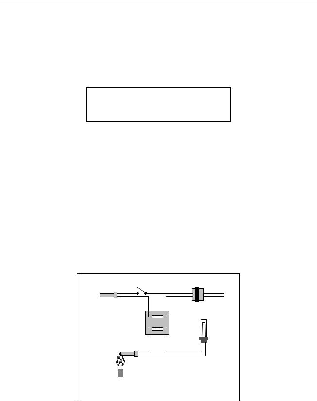
PILOT IGNITION SYSTEM
The pilot ignition system is comprised of the pilot orifice, pilot hood, and a thermopile. The pilot serves two purposes. The first is to light the burner, the second is to heat the thermopile. In operation, the thermopile is in contact with the pilot flame and generates millivolts. The millivolt output passes through a normally closed high-limit switch and energizes the gas valve pilot coil, which in turn opens the pilot valve. If the pilot flame is extinguished, voltage is lost to the gas valve pilot coil and the pilot valve closes. A separate 24-volt circuit, activated by the fryer ON/OFF switch, provides voltage through the thermostat or controller to the gas valve main coil, which opens the main valve. The gas valve is constructed so that the main valve will not open if the pilot valve is not open. The pilot flame must be manually lit (either with a match or with an optional built-in piezo igniter) when the fryer is first placed into operation.
|
|
ON/OFF |
|
|
|
Switch |
Line Voltage |
|
|
|
|
Controlling Thermostat |
|
Line Voltage |
|
|
24 VAC |
||
or |
|
Main Coil |
|
|
Transformer |
||
Controller |
|
||
|
|
||
|
|
|
|
|
|
Gas Valve |
|
|
|
|
High-Limit |
|
|
|
Thermostat |
|
|
Pilot Coil |
|
|
Thermopile |
|
|
|
Pilot |
The Pilot System |
|
|
|
||
|
|
1-1 |
|

CONTROL OPTIONS
45 Series fryers may be equipped with thermostat controllers, analog controllers, digital controllers, basket lift timers, or Computer Magic computers.
In fryers equipped with thermostat controls, the fryer and melt cycle are turned on and off by means of rocker switches and the temperature is set by means of a knob connected directly to the frypotmounted thermostat. These units have no interface board. In this type of unit, when the melt cycle switch is placed in the ON position, the fryer stays in the melt cycle mode until the switch is manually placed in the OFF position, even if the frypot is at setpoint temperature.
Fryers equipped with other types of controllers have an interface board located in the component shield behind the control panel.
INTERFACE BOARDS
The interface board provides the link between the controller/computer and the fryer’s individual components without requiring excessive wiring, and allows the controller to execute commands from one central point. When built, depending upon the configuration of the particular fryer, any one of three different boards may be used. Regardless of the particular board installed when the fryer was built, P/N 806-3548 is the universal replacement part.
1 |
4 |
7 |
10 |
13 |
3 |
6 |
9 |
12 |
2 |
5 |
8 |
11 |
14 |
2 |
5 |
8 |
11 |
3 |
6 |
9 |
12 |
15 |
1 |
4 |
7 |
10 |
NOTES:
1.RELAYS K1 AND K2 ARE FOR BELL CRANK BASKET LIFTS. THEY ARE NOT PRESENT ON BOARDS 806-5490 (U.S. AND NON-CE EXPORT UNITS W/O BASKET LIFTS) OR 806-7501 (CE UNITS, WITH OR WITHOUT BASKET LIFTS).
2.RESISTORS R1, R10, AND R15 ARE NOT USED ON ANY OF THE THREE BOARDS.
3.RESISTORS R11 AND R12 ARE NOT USED ON 806-5490 BOARDS.
INTERFACE BOARDS 806-3548, 806-5490, AND 806-7505
1-2
FREQUENTLY USED TEST POINTS FOR 45 SERIES INTERFACE BOARDS
|
Meter |
|
|
Test |
Setting |
Pins |
Results |
12 VAC Power to Controller |
50 VAC Scale |
1 and 3 of J2 |
12-18 |
24 VAC Power |
50 VAC Scale |
24 VAC Terminals |
22-28 |
24 VAC Power to Gas Valve |
50 VAC Scale |
6 on J1 and GROUND |
22-28 |
120 VAC Power |
250 VAC Scale |
7 and 12 of J1 |
110-125 |
Probe Resistance* |
R x 1000 OHMS |
2 and 3 of J1 |
** |
*Disconnect 15-Pin harness from controller before testing probe circuit.
**See Probe Resistance Chart at end of chapter.
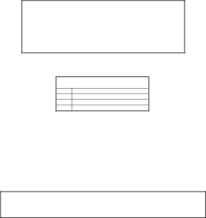
Four LEDs, arranged across the top of the boards and identified in the table below, are provided to assist in troubleshooting.
45 SERIES INTERFACE BOARD LED DIAGNOSTIC LIGHTS
GV Indicates 24 VAC to the gas valve
AL Indicates open Drain Safety Switch (if installed)
24V Indicates 24 VAC from transformer
COMP Indicates 12 VAC to computer
Every board contains one heat relay (K3), and may contain two basket lift relays (K1 and K2). As shipped from the factory, fryers with bell crank basket lifts will have relays K1, K2, and K3. All other factory-original fryers will have boards with only relay K3.
THERMOSTATS AND TEMPERATURE PROBES
Different types of thermostats are used in 45 Series fryers, depending on the fryers’ configuration.
Fryers equipped with Thermostat Controls have an adjustable controlling (operating) thermostat. The temperature at which the thermostat opens and closes is adjusted by physically changing the setting of the thermostat itself by means of an attached knob. When new, the Fenwal controlling thermostat used in 45 Series fryers is sensitive to one-degree changes in temperature.
 CAUTION
Fenwal thermostats are used in a number of Frymaster products. The thermostat for the 45 Series is 4 inches long. Do not use 3-inch Fenwal thermostats in 45 Series fryers.
Fryers equipped with all other type controls have a temperature probe. In these units, the probe resistance varies directly with the temperature. That is, as the temperature rises, so does resistance at a rate of approximately 2 ohms for every 1º (F or C). Circuitry in the controller monitors the probe resistance and controls burner firing when the resistance exceeds or falls below programmed temperatures (setpoints). The temperatures are programmed by means of a keypad on the face of the controller.
All 45 Series fryers are equipped with a high-limit thermostat. In the event that the fryer fails to properly control the oil temperature, the high-limit thermostat prevents the fryer from overheating to the flash point. The high-limit thermostat acts as a normally closed power switch that opens when
1-3
exposed to temperatures in the range of 425ºF to 450ºF (218ºC to 232ºC). The high-limit thermostat is the same for CE and Non-CE applications, but the terminals for attaching it to Robertshaw and Honeywell gas valves differ. When a replacement high-limit thermostat is ordered, make sure the kit appropriate for the valve in use is ordered.
1.2Accessing Fryers for Servicing
 DANGER
Moving a fryer filled with cooking oil/shortening may cause spilling or splattering of the hot liquid. Follow the draining instructions in Chapter 4 of the 45 Series Gas Fryer Installation and Operation Manual before attempting to relocate a fryer for servicing.
1.Shut off the gas supply to the unit. Unplug the power cord(s). Disconnect the unit from the gas supply.
2.Remove any attached restraining devices.
3.Relocate the fryer for service accessibility.
4.After servicing is complete, reconnect the unit to the gas supply, reattach restraining devices, and plug in the electrical cords.
1.3Checking the Burner Manifold Gas Pressure
 WARNING
This task should be performed by qualified service personnel only.
1.Ensure that the gas valve knob or button is in the OFF position.
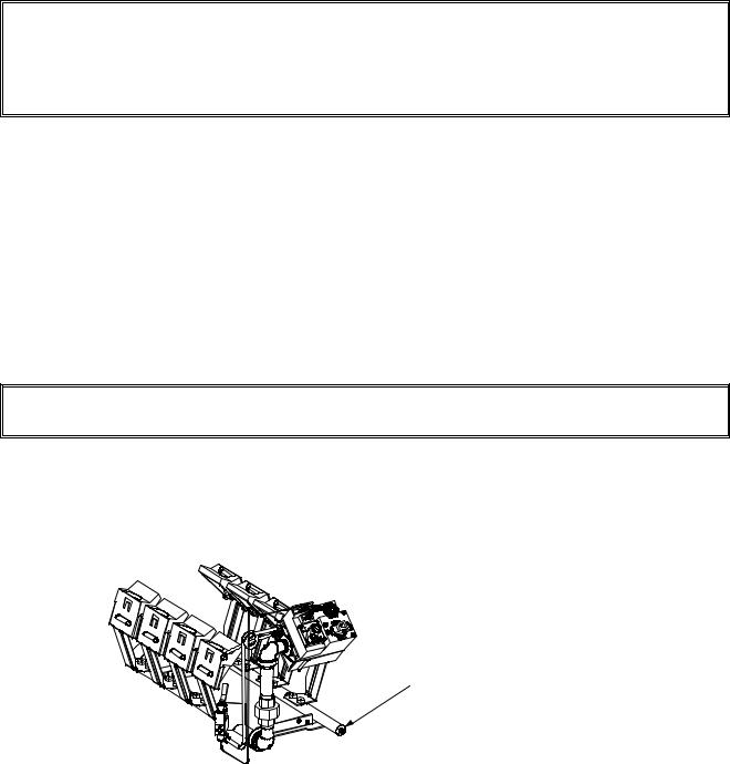
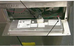
2.Remove the pressure tap plug from the end of the manifold (see illustration below for location) and connect a gas pressure-measuring device to the port.
Remove this plug and connect a gas pressure-measuring device to the port.
3.Place the gas valve in the ON position then place the fryer power switch in the ON position. When the burner lights and continues to burn, compare the pressure reading to that for the corresponding gas in the tables on the following page.
1-4
Non-CE Standard
Burner Manifold Gas Pressures
|
Gas |
Pressure |
|
|
|
|
|
Natural |
3.5" W.C. |
|
|
|
|
|
0.73 kPa |
|
|
|
|
|
|
|
|
|
|
|
|
|
Propane |
8.25" W.C. |
|
|
|
|
|
2.05 kPa |
|
|
|
|
|
|
|
|
|
|
|
|
|
|
|
|
|
|
|
|
|
|
|
|
|
|
CE Standard
Burner Manifold Gas Pressures
Gas |
Pressure |
|
|
(mbar) |
|
|
|
|
|
|
|
Natural Gas Lacq |
7,5 |
|
|
(G20) under 20 mbar |
|
|
|
|
|
|
|
Natural Gas Gronique * |
10 |
|
|
(G25) under 25 mbar |
|
|
|
|
|
|
|
Natural Gas Gronique |
10 |
|
|
(G20) under 20 mbar |
|
|
|
|
|
|
|
Propane |
20,6 |
|
|
(G31) under 37 or 50 mbar |
|
|
|
|
|
|
|
* Belgian G25 = 7,0 mbar |
|
|
|
|
|
|
|
|
|
|
|
4.If the measured gas pressure does not match the appropriate pressure in the tables above, remove the cap from the gas valve regulator and adjust to the correct pressure.
Robertshaw Valve |
Honeywell Valve |
Honeywell Valve |
(Non-CE Units) |
(Non-CE Units) |
(CE Units) |
Regulator Adjustment Screw Cap
5.Place the fryer power switch and the gas valve in the OFF position. Remove the fitting from the pressure tap hole and reinstall the plug. Place the gas valve in the ON position, and check for and eliminate any gas leaks. Place the gas valve in the OFF position.
1.4Adjusting the Pilot Flame
1.On non-CE valves, remove the cap covering the pilot adjustment screw. On all valves, turn the pilot adjustment screw counterclockwise to increase the length of the flame or clockwise to decrease the length of the flame. Adjust the flame to a length of 1 to 1½ inches (25 to 38mm).
To access the pilot adjustment screw on |
Pilot Adjustment Screw |
Non-CE valves, this cap must be removed. |
|
Robertshaw Valve |
Honeywell Valve |
Honeywell Valve |
(Non-CE Units) |
(Non-CE Units) |
(CE Units) |
2. On Non-CE valves, reinstall the pilot adjustment screw cap.
1-5
1.5Cleaning the Gas Valve Vent Tube
1.Carefully unscrew the vent tube from the gas valve. NOTE: The vent tube may be straightened for ease in removal.
2.Pass a piece of ordinary binding wire (.052 inch diameter) or equivalent through the tube to remove any obstruction.
3.Remove the wire, then blow through the tube to ensure it is clear.
4.Reinstall tube and bend it so that the opening is pointing downward.
1.6Adjusting Burner Ceramic Target Spacing and Alignment
 DANGER
Drain the frypot or remove the handle from the drain valve before proceeding further.
Proper spacing of the top edge of the burner ceramic targets is ¾ inch (13 mm) from the frypot side. To adjust target spacing, bend the brackets to which they are attached away or toward the frypot to the proper distance. (A length of board of the proper thickness is useful as a gauge to verify spacing and alignment.)
1.7Calibrating the Thermostat Control
NOTE: The fryer control panel must be hinged down from the control panel mounting frame to perform thermostat calibration. In order to hinge the control panel down, the thermostat knob must be removed from its shaft. It is secured with a setscrew located opposite the index mark on the knob.
1.Fill the frypot to the lower OIL-LEVEL line with cooking oil/shortening. If solid shortening is used, it must be pre-melted before starting the calibration procedure.
2.Ensure the fryer ON/OFF Switch is in the OFF position, then light the pilot. (Refer to Chapter 3 of the 45 Series Gas Fryer Installation and Operation Manual for detailed lighting instructions.)
3.Insert a good grade thermometer or pyrometer into the frypot so that it touches the thermostat guard.
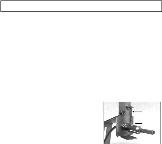
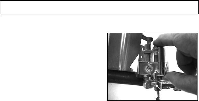
4.Loosen the setscrew and stop screw securing the ther-
mostat shaft extension to the flexible shaft. Remove |
Stop screw |
|
the extension to expose the slot in the end of the flexi- |
||
|
||
ble shaft. |
Locking nut |
|
|
||
5. Place the fryer ON/OFF switch in the ON position. |
|
|
NOTE: If the burner does not light at this time, it |
Setscrew |
|
|
||
does not mean the thermostat is defective! |
|
Use a small flat-tipped screwdriver to slowly turn the flexible shaft counterclockwise until the burner lights. Turning the shaft counterclockwise causes the burner to light and clockwise causes it to shut off.
1-6
6.When the cooking oil/shortening temperature reaches 325ºF (162ºC), turn the flexible shaft slowly clockwise until the burner shuts off.
7.Allow the fryer to sit for a few minutes, then slowly turn the flexible shaft counterclockwise until the burner lights.
8.Repeat steps 6 and 7 at least three times to ensure an accurate setting is obtained. The Thermostat Control is considered to be properly calibrated when the burner lights as the cooking oil/shortening cools to 325ºF (162ºC)—not when the burner shuts off as the temperature rises.
9.Once the calibration point of 325ºF (162ºC) is determined, allow the burner to cycle on and off at least 3 times to be sure it will light at the calibrated temperature.
10.After the calibration is complete, place the fryer power switch in the OFF position and disconnect the fryer from the electrical supply.
11.Carefully replace the thermostat shaft extension, ensuring that the stop screw is pointed straight up. Tighten the stop screw and locking nut and the setscrew, being careful not to rotate the flexible shaft.
 CAUTION
The thermostat flexible shaft must not be rotated while installing the thermostat shaft extension!
When handling the thermostat, do not rotate the shaft more than two turns in either direction. Doing so will cause damage to the thermostat.
12.Close the fryer control panel and replace the screws the upper corners.
13.Reinstall the thermostat knob with its pointer aligned with the 325ºF (162ºC) index mark on the temperature dial.
14.Reconnect the fryer to the electrical supply.
1.8Replacing Fryer Components
1.8.1 Replacing the Controller or Computer
1.Disconnect the fryer from the electrical power supply.
2.Unscrew the two control panel screws. The control panel is hinged at the bottom and will swing open from the top.
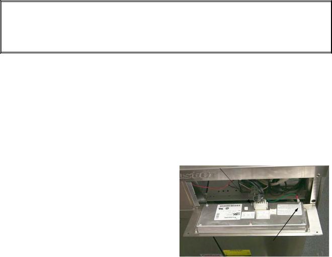
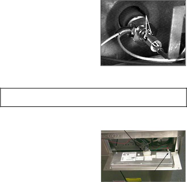
3.Unplug the fryer wiring harness from the back of the controller/computer and disconnect the grounding wire.
Unplug harness
Disconnect grounding wire
1-7
4.Remove the controller/computer by lifting it from the hinge slots in the fryer control panel frame.
5.Reverse the procedure to install a new controller/computer.
1.8.2 Replacing the Operating Thermostat
 CAUTION
The thermostat must be calibrated after installation is complete. Refer to Section 1.7 for calibration instructions.
When handling the thermostat, do not rotate the shaft more than two turns in either direction. Doing so will cause damage to the thermostat.
1.Disconnect the fryer from the electrical supply and drain the frypot.
2.Loosen the setscrew securing the thermostat knob and remove the knob. Remove the screws from the upper left and right corners of the control panel. The control panel is hinged at the bottom and will swing open from the top.
3.Disconnect the 9-Pin connector and remove the control panel from the fryer by disengaging its tabs from the hinge slots in the mounting frame.
4.Loosen the setscrews securing the flexible shaft
to the thermostat shaft and slip the flexible shaft |
Loosen these setscrews and slip the |
|
flexible shaft off the thermostat shaft. |
||
off the thermostat shaft. |
||
|
5.Remove the flexible shaft guide by removing the two sheet metal screws securing it to the upper frame.
6.Disconnect the thermostat leads from Pin 14 in the 20-pin terminal block and from the gas valve terminal.
NOTE: If the fryer is configured with a melt cycle, the thermostat leads will be connected to the melt cycle timer motor or PC board rather than to the terminal block and gas valve. Disconnect the leads from the motor or PC board if this is the case.
7.Unscrew the thermostat from the frypot and remove.
8.Apply Loctite™ PST56765 thread sealant or equivalent to the replacement thermostat threads.
9.Reverse steps 1 through 7 to install the replacement.
1.8.3Replacing the Temperature Probe
1. Disconnect the fryer from the electrical supply.
1-8
2.Drain the frypot.
3.Remove the screws from the upper left and right corners of the control panel. The panel is hinged at the bottom and will swing open from the top.
4.Unplug the wiring harness from the back of the controller and disconnect the grounding wire.
5.Remove the controller from the fryer by lifting it from the hinge slots in the control panel frame.
Unplug harness
Disconnect grounding wire
6.Remove the two screws from the base of the interface board mounting bracket.
7.Disconnect the 12-pin plug from the back of the interface board and lay the board in the left end of the compartment with all other wires still connected.
8.Remove the 12-volt transformer from the component shield and lay it in the left end of the compartment with wires still connected.
9.Using a pin-pusher, remove the temperature probe wires (pins 1 and 2) from the 12-pin plug disconnected in step 7.
10.Unscrew the temperature probe from the frypot and remove.
11.Apply Loctite™ PST56765 thread sealant or equivalent to new probe threads.
12.Reverse steps 1 through 10 to install the replacement probe.
1.8.4 Replacing the High-Limit Thermostat in Fryers with Thermostat Controls
1.Disconnect the fryer from the electrical supply.
2.Drain the frypot.
3.Loosen the setscrew securing the thermostat knob and remove the knob. Remove the screws from the upper left and right corners of the control panel. The control panel is hinged at the bottom and will swing open from the top.
4.Disconnect the 9-Pin connector and remove the control panel from the fryer by disengaging its tabs from the hinge slots in the mounting frame.
6.Disconnect the high-limit thermostat leads from the gas valve pilot coil.
7.Unscrew the high-limit thermostat from the frypot and remove.
8.Apply Loctite™ PST56765 thread sealant or equivalent to the replacement thermostat threads.
9.Reverse steps 1 through 7 to install the replacement.
1-9

1.8.5Replacing the High-Limit Thermostat in Fryers with Other Than Thermostat Controls
1.Disconnect the fryer from the electrical power supply.
2.Drain the frypot.
3.Remove the screws from the upper left and right corners of the controller panel. The controller is hinged at the bottom and will swing open from the top.
4.Unplug the wiring harness and disconnect the grounding wire from the the controller.
Unplug harness
Disconnect grounding wire
5.Remove the controller from the fryer by lifting it from the hinge slots in the fryer control panel frame.
6.Remove the two screws from the base of the interface board mounting bracket.
7.Disconnect the 12-pin plug from the back of the interface board and lay the board in the right end of the compartment with all other wires still connected.
8.Remove the 12-volt transformer and lay it in the right end of the compartment with wires still connected.
9.Remove the high-limit thermostat wires from the gas valve pilot coil and pull them up through the control shield.
10.Unscrew the high-limit thermostat from the frypot and remove.
11.Apply Loctite™ PST56765 thread sealant or equivalent to the replacement thermostat’s threads and screw it into the frypot.
12.Attach the appropriate terminals (furnished in the replacement thermostat kit) to the thermostat leads.
13.Reverse steps 1 through 9 to complete installation of the replacement thermostat.
1.8.6 Replacing the Heat Mode Indicator Light in Fryers with Thermostat Controls
1.Disconnect the fryer from the electrical supply.
2.Loosen the setscrew securing the thermostat knob and remove the knob. Remove the screws from the upper left and right corners of the control panel. The control panel is hinged at the bottom and will swing open from the top.
1-10
3.Disconnect the 9-pin connector and remove the control panel from the fryer by disengaging its tabs from the hinge slots in the mounting frame.
4.Carefully press the light out from the back of the control panel. Disconnect one wire at a time and reconnect it to the replacement light until all wires are transferred.
5.Carefully press the light back into the control panel.
6.Reverse steps 1-3 to reassemble the fryer.
1.8.7 Replacing the Power or Melt Cycle Switch in Fryers with Thermostat Controls
1.Disconnect the fryer from the electrical supply.
2.Loosen the setscrew securing the thermostat knob and remove the knob. Remove the screws from the upper left and right corners of the control panel. The control panel is hinged at the bottom and will swing open from the top.
3.Disconnect the 9-pin connector and remove the control panel from the fryer by disengaging its tabs from the hinge slots in the mounting frame.
4.Using a flat-tipped screwdriver, disconnect the chrome bezel from the tabs on the switch and press the switch out from the front.
5.Carefully press the new switch back into the chrome bezel, making sure the tabs on the switch engage the slots in the bezel.
6.Disconnect one wire at a time from the old switch and reconnect it to the new switch until all wires have been transferred.
7.Reverse steps 1-3 to reassemble the fryer.
1.8.8 Replacing the Melt Cycle Timer in Fryers with Thermostat Controls
NOTE: In early 1999, PC board melt cycle timers replaced melt cycle timer motors in new fryers.
1.Disconnect the fryer from the electrical supply.
2.Loosen the setscrew securing the thermostat knob and remove the knob. Remove the screws from the upper left and right corners of the control panel. The control panel is hinged at the bottom and will swing open from the top.
3.Remove the screws securing the timer motor (or the PC board timer bracket) to the fryer (see illustration on Page 2-16).
4.Remove one wire at a time and reconnect it to the replacement PC board timer until all wires have been transferred.
5.Reverse steps 1-3 to reassemble the fryer.
1-11

1.8.9 Replacing Burner Ceramic Targets
 DANGER
Drain the frypot or remove the handle from the drain valve before proceeding further.
1.Disconnect fryer from electrical and gas supplies.
2.On FM45 fryers, remove square-drain sections as necessary to expose burner.
3.Disconnect the wires from the gas valve terminal block, marking each wire to facilitate reconnections.
4.Remove the high-limit thermostat wires from the gas valve pilot coil.
5.Disconnect the pipe union collar at the right side of the gas valve.
6.Remove the burner heat shield hanger screws at the front of the burner and remove the heat shield.
7.Remove the burner hanger screws and lower the front of the main burner. Pull it forward to clear the rear burner hanger, then lower the burner to the floor.
8.Raise the front of the fryer enough to slide the burner from under the fryer cabinet.
9.To replace only the ceramic targets, straighten the target locking tabs with a pair of needle nose pliers or a screwdriver, and slide the target up and off the bracket. Slide the replacement target onto the bracket and bend the locking tabs down.
To replace the entire target assembly, use a ½-inch (13mm) box end wrench to remove the two brass orifices that hold the assembly to the burner manifold. Position the new assembly and replace the orifices.
 WARNING
Use extreme care to prevent cross-threading and stripping when reinstalling the brass orifices.
10.Reverse steps 1-8 to reinstall the burner assembly. Check spacing and alignment of targets in accordance with Section 1.5.
1.8.10 Replacing the Gas Valve
 DANGER
Drain the frypot or remove the handle from the drain valve before proceeding further.
1. Disconnect fryer from electrical and gas supplies
1-12
2.Disconnect the wires from the gas valve terminal block, marking each wire to facilitate reconnections.
3.Remove the high-limit thermostat wire from the gas valve pilot coil.
4.Disconnect the pilot gas line fitting from the gas valve.
5.Disconnect the pipe union collars to the left and right of the gas valve and remove the valve.
6.Remove the pipe fittings from the old gas valve and install on the replacement valve, using Loctite™ PST56765 or equivalent pipe thread sealant on threads.
7.Reverse steps 1-5 to install the replacement gas valve.
1.8.11 Replacing the Pilot Assembly or Thermopile
 DANGER
Drain the frypot or remove the handle from the drain valve before proceeding further.
1.Remove the burner assembly in accordance with steps 1-8 of Section 1.8.9.
2.To replace only the thermopile:
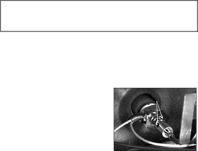
a.Bend the clip at the bottom of the pilot assembly and press the thermopile out of the pilot assembly from the top.
b.Disconnect the thermopile fitting from the gas valve pilot coil.
c.Reverse steps a and b to install the replacement thermopile.
Bend clip to release thermopile.
3.To replace the complete pilot assembly:
a.Disconnect the pilot tubing from the bottom of the pilot assembly.
b.Remove the screw from the pilot mounting bracket to release the pilot assembly.
c.Disconnect the thermopile fitting from the gas valve pilot coil.
d.Reverse steps a through c to install the replacement pilot assembly.
4.Reinstall the burner assembly by reversing steps 1-8 of Section 1.8.9.
1-13
1.8.12 Replacing the Frypot
1.Drain the frypot.
2.Remove all accessories (e.g., frypot covers, basket lift arms, etc.) from the fryer.
3.Disconnect the fryer from gas and electrical supplies.
4.Remove the screws from the top cap above the control panel and lift it up and off the fryer(s).
5.If the fryer is equipped with other than a thermostat control, skip to Step 10.
6.Loosen the setscrew securing the thermostat knob to the thermostat flexible shaft and remove the knob. Remove the screws from the upper left and right corners of the control panel. Disconnect the 9-pin connector and remove the control panel from the fryer.
7.Loosen the setscrews securing the flexible
shaft to the thermostat shaft and slip the flexi- |
Loosen these setscrews and slip |
ble shaft off the thermostat shaft. |
flexible shaft off the thermostat shaft. |
8.Remove the flexible shaft bracket from the fryer by removing the two sheet metal screws securing it to the upper frame.
9.Disconnect the thermostat leads from Pin 14 in the 20-pin terminal block and from the gas valve terminal. Mark each wire to facilitate reconnection. Skip to Step 14.
NOTE: If the fryer is configured with a melt cycle, the thermostat leads will be connected to the melt cycle timer motor rather than to the terminal block and gas valve. Disconnect the leads from the motor if this is the case.
 CAUTION
When handling the thermostat, do not rotate the shaft more than two turns in either direction. Doing so will cause damage to the thermostat.
10.For fryers equipped with other than Thermostat Controls, remove the screws from the upper left and right corners of the control panel. Unplug the wiring harness from the back of the controller and disconnect the grounding wire. Remove it from the fryer by lifting it from the hinge slots in the fryer control frame.
11.Remove the two screws from the base of the interface board bracket.
12.Disconnect the 12-pin plug from the back of the interface board. Use a pin pusher to re-
move the temperature probe leads (pins 1 and
Unplug harness
Disconnect grounding wire
1-14
2) and the high-limit thermostat leads (pins 6 and 8) from the plug. Leave all other wires connected. Leave the interface board lying on the shield.
13.Remove the louvered frame above the control panel opening.
14.Remove the screws securing the component shield to the fryer.
15.Disconnect the wires from components in component shield and mark to facilitate reconnection.
16.Disconnect the wires from the gas valve terminal block. Mark each wire to facilitate reconnection.
17.Remove the cover from the safety drain switch, disconnect the wires from the switch, and pull them out of the switch box.
18.Pull up and forward on the component shield to clear the rear mounting stud on the front of the frypot and remove it from the fryer by rotating its right side up and to the left.
19.Disconnect the pipe union on the right side of the gas valve.
20.On FM45 fryers, remove the section of square drain from the drain valve of the frypot to be removed.
21.Remove the frypot hold down bracket.
22.Remove the screws from the flue cap sides and back and lift it clear of the fryer(s).
23.Remove the oil return line from the front of the frypot to be removed.
24.Lift the complete frypot assembly (frypot, burner, gas valve, and flue) from the fryer cabinet.
25.Transfer the burner heat shield and burner to the replacement frypot.
26.Remove the drain valve, thermostat or temperature probe, and high-limit thermostat and install on replacement frypot.
 CAUTION
Before installing the thermostat/temperature probe, high-limit thermostat, and drain valve on the replacement frypot, clean their threads and apply Loctite™ PST56765 thread sealant or equivalent to the threads.
27. Reverse steps 1-25 to reassemble the fryer.
1.9Troubleshooting and Problem Isolation
Because it is not feasible to attempt to include in this manual every conceivable problem or trouble condition that might be encountered, this section is intended to provide technicians with a general knowledge of the broad problem categories associated with this equipment, and the probable causes of each. With this knowledge, the technician should be able to isolate and correct any problem encountered.
1-15
Problems you are likely to encounter can be grouped into seven broad categories:
1. |
Ignition failures |
5. |
Filtration problems |
2. |
Improper burner functioning |
6. |
Leakage problems |
3. |
Improper temperature control |
7. |
Basket lift malfunctions |
4. |
Computer-related problems |
|
|
The probable causes of each category are discussed in the following sections. A series of Troubleshooting Guides (decision trees) is also included at the end of the chapter to assist in identifying some of the more common problems.
1.9.1 Ignition Failures
Ignition failures occur when the 24VAC power supply to the gas valve is interrupted, when the gas supply is interrupted, or when the pilot flame is extinguished.
Solid-state controllers indicate ignition failure by illuminating the heat light and trouble light simultaneously. All other controllers give no specific indication of an ignition failure.
There are three primary reasons for ignition failure, listed in order of probability:
1.Problems related to the gas and/or electrical power supplies.
2.Problems related to the electronic circuits.
3.Problems related to the gas valve.
PROBLEMS RELATED TO THE GAS AND/OR ELECTRICAL POWER SUPPLIES
The main indicators of this are that an entire battery of fryers fails to light and/or there are no indicator lights illuminated on the fryer experiencing ignition failure. Verify that the quick disconnect hose is properly connected, the fryer is plugged in, the main gas supply valve is open, and the circuit breaker for the fryer electrical supply is not tripped.
PROBLEMS RELATED TO THE ELECTRONIC CIRCUITS
If gas and electrical power are being supplied to the fryer, the next most likely cause of ignition failure is a problem in the 24 VAC circuit of the pilot system. If the fryer is equipped with a Filter Magic II filtration system, first verify that the drain valve is fully closed. (The valve is attached to a microswitch that must be closed for power to reach the gas valve. Often, although the valve handle appears to be in the closed position, the microswitch is still open.) If the valve is fully closed, or the fryer does not have a filtration system, refer to the troubleshooting guides TROUBLESHOOTING THE 24 VAC CIRCUIT.
PROBLEMS RELATED TO THE GAS VALVE
If the problem is not in the 24 VAC circuit of the pilot system, it is most likely in the gas valve itself, but before replacing the gas valve refer to TROUBLESHOOTING THE GAS VALVE on page 1–32.
1-16

1.9.2 Improper Burner Functioning
With problems in this category, the burner ignites but exhibits abnormal characteristics such as “popping,” incomplete lighting of the burner, fluctuating flame intensity, and flames “rolling” out of the fryer.
“Popping” indicates delayed ignition. In this condition, the main gas valve is opening but the burner is not immediately lighting. When ignition does take place, the excess gas “explodes” into flame, rather than smoothly igniting.
The primary causes of popping are:
•Incorrect or fluctuating gas pressure
•Misdirected or weak pilot flame
•Burner deflector targets out of alignment or missing
•Clogged burner orifices
•Inadequate make-up air
•Clogged vent tube, causing incorrect gas pressure
If popping occurs only during peak operating hours, the problem may be incorrect or fluctuating gas pressure. Verify that the incoming gas pressure (pressure to the gas valve) is in accordance with the appropriate CE or Non-CE Standard found in the table below, and that the pressure remains constant throughout all hours of usage. Refer to Checking the Burner Manifold Pressure (Section 1.3) for the procedure to checking the pressure of gas supplied to the burner.
Non-CE Standard
for Incoming Gas Pressures
|
Gas |
Minimum |
Maximum |
|
|
|
|
|
|
6" W.C. |
14" W.C. |
|
|
|
|
|
Natural |
1.49 kPa |
3.48 kPa |
|
|
|
|
|
|
14.93 mbar |
34.84 mbar |
|
|
|
|
|
|
11" W.C. |
14" W.C. |
|
|
|
|
|
LP |
2.74 kPa |
3.48 kPa |
|
|
|
|
|
|
27.37 mbar |
34.84 mbar |
|
|
|
|
|
|
|
|
|
|
|
|
|
|
|
|
|
|
|
|
CE Standard
for Incoming Gas Pressures
|
Pressure |
|
Regulator |
|
Gas |
(mbar)(1) |
Orifice Diameter |
Pressure |
Consumption |
G20 |
20 |
18 x 1,40 mm |
7,5 mbar |
3,00 m3/h |
G25 |
20 - 25 |
18 x 1,40 mm |
10 mbar |
3,50 m3/h |
G31 |
37 - 50 |
18 x 0,86 mm |
20,6 mbar |
2,21 kg/h |
(1) mbar = 10,2 mm H2O
If popping is consistent during all hours of operation, verify that the pilot is properly positioned above the burner orifice and that the pilot pressure is correct. Correct pilot pressure is indicated by a flame 1 to 1½” (25 to38 mm) long. Refer to Section 1.6 for the pilot flame adjustment procedure.
Clogged burner orifices, especially those near the pilot, are also likely causes of delayed ignition. Clogged orifices are indicated by no flame, flames that are orange-colored, and flames that shoot out at an angle from the rest.
Another cause of popping is an insufficient air supply or drafts that are blowing the pilot flame away from the burner. Check for “negative pressure” conditions in the kitchen area. If air is flowing into the kitchen area, this indicates that more air is being exhausted than is being replenished and the burners may be starved for air.
1-17
If the fryer’s gas and air supplies are okay, the problem most likely is with one of the electrical components. Examine the controller for signs of melting/distortion and/or discoloration due to excessive heat buildup in the fryer. (This condition usually indicates improper flue performance.). A discolored or distorted controller is automatically suspect and should be replaced. However, unless the condition causing excessive heat in the fryer is corrected, the problem is likely to recur.
The burner lighting on one side only may be caused by a missing or misaligned rear deflector target or improper burner manifold pressure. Clogged burner orifices are usually the cause of gaps in burner firing.
Fluctuating flame intensity is normally caused by either improper or fluctuating incoming gas pressure, but may also be the result of variations in the kitchen atmosphere. Verify incoming gas pressure in the same way as for “popping,” discussed in the preceding paragraphs. Variations in the kitchen atmosphere are usually caused by air conditioning and/or ventilation units starting and stopping during the day. As they start and stop, the pressure in the kitchen may change from positive or neutral to negative, or vice versa. They may also cause changes in airflow patterns that may affect flame intensity.
Flames “rolling” out of the fryer are usually an indication of negative pressure in the kitchen. Air is being sucked out of the fryer enclosure and the flames are literally following the air. If negative pressure is not the cause, check for high burner manifold gas pressure in accordance with the procedures in Section 1.3, Checking the Burner Manifold Pressure. An obstructed flue, which prevents the fryer from properly exhausting, may also be the cause.
An excessively noisy burner, especially with flames visible above the flue opening, may indicate that the burner gas pressure is too high, or it may simply be that the gas valve vent tube is blocked. If the gas pressure is correct and the vent tube in unobstructed, the gas valve regulator is probably defective.
Occasionally a burner may apparently be operating correctly; nevertheless, the fryer has a slow recovery rate. (The recovery rate is the length of time required for the fryer to increase the oil temperature from 250ºF to 300ºF (121ºC to 149ºC)). The primary causes of this are low burner manifold pressure and/or misaligned or missing deflector targets. If both of these causes are ruled out, the probable cause is a gas valve regulator that is out of adjustment. Refer to Checking the Burner Manifold Pressure in Section 1.3.
1.9.3 Improper Temperature Control
Temperature control, including the melt cycle, is a function of several interrelated components, each of which must operate correctly. The principle component is the thermostat (in thermostat control units) or the temperature probe (in fryers equipped with other types of controllers). Depending upon the specific configuration of the fryer, other components may include the interface board and the controller.
Improper temperature control problems can be categorized into melt cycle problems and failure to control at setpoint problems.
1-18

MELT CYCLE PROBLEMS
In fryers equipped with thermostat controls, the melt cycle is controlled by a mechanical timer. There are three components that may fail: the melt cycle timer itself, the melt cycle timer microswitch, or the control panel melt cycle ON/OFF switch. In all cases, the defective component must be replaced.
In fryers equipped with other types of controllers, the problem may be with the controller itself, the temperature probe, or a malfunctioning heat relay on the interface board.
For problem isolation techniques, refer to the troubleshooting guides TROUBLESHOOTING THE THERMOSTAT and
FAILURE TO CONTROL AT SETPOINT
In fryers equipped with thermostat controls, the problem will be with the thermostat itself. Possible causes are that the thermostat is out of calibration, the knob or flexible shaft is loose on the thermostat shaft, a thermostat wire is disconnected or broken, or the thermostat is defective. Refer to Section 1.7 for instructions on calibrating the thermostat.
In fryers equipped with other types of controls, the problem may be with the temperature probe, the interface board, or the controller. Refer to the troubleshooting guide
for problem isolation techniques.
1.9.4 Computer-Related Problems
COMPUTER MAGIC FEATURES
SENSITIVITY OR “STRETCH AND SHRINK TIME”
Sensitivity or stretch time is a programmable feature, patented by Frymaster that increases or decreases the cook time countdown based on variations in the oil temperature from the set point.
The sensitivity for each product button has ten settings (0 through 9). A zero sensitivity setting will disable the feature (no change in cooking time), while a nine will provide the highest sensitivity or most change. The correct sensitivity for any product is based on the product, its density, the set point temperature, and the customer’s own requirements.
RECOVERY TIME
Recovery time or rate of rise is a method of measuring a fryer’s performance. Put simply, it is the time required for the fryer to increase the oil temperature from 250ºF to 300ºF (121ºC to 149ºC). This range is used as a standard since ambient kitchen temperatures can effect the test if lower ranges are used.
The Computer Magic performs the recovery test each day as the fryer warms up. An operator can view the results of the test any time the fryer is above the 325ºF (163ºC) point by pressing the  button and entering the code 1652. The test results will be displayed in the computer’s LED panel in minutes and seconds. The acceptable recovery time for 45 Series fryers is 2 minutes and 25 seconds.
1-19

COMMON COMPUTER COMPLAINTS
Most problems concerning computers have to do with programming them. There are four common complaints. The complaints, their causes, and corrective actions are:
1.Fryer constantly displays “HI.” Cause: Setpoint incorrect or missing.
Corrective Action: Press 


 1650, enter the correct setpoint using keypad, then press
  to lock in the setpoint.
2.Temperature is displayed in Celsius.
Cause: Computer is programmed to display in Celsius. Corrective Action: Press 

 1658.
1658.
3.Temperature is constantly displayed.
Cause: Computer is programmed for constant temperature display. Corrective Action: Press 

 165L.
165L.
4.Computer times down too slowly or too quickly.
Cause: Computer is compensating for oil temperature via the sensitivity setting.
Corrective Action: Reprogram sensitivity setting for each product in accordance with programming instructions in Chapter 3 of the 45 Series Gas Fryer Installation and Operation Manual.
1.9.5Filtration Problems
The majority of filtration problems arise from operator error. One of the most common errors is placing the filter paper on the bottom of the filter pan rather than over the filter screen.
Whenever the complaint is “the pump is running, but no oil is being filtered,” check the installation of the filter paper, including that the correct size is being used. While you are checking the filter paper, verify that the O-rings on the bottom of the filter pan and on the male disconnect (at inside rear of filter cabinet) are present and in good condition. Missing or worn O-rings will allow the pump to suck air and decrease its efficiency.
If the pump motor overheats, its thermal overload will trip and the motor will not start until it is reset. If the pump motor does not start, press the red reset switch located on the end of the motor nearest the operator. If the pump then starts, something caused the motor to overheat. It may be just that several frypots were being filtered one after the other and the pump got hot. Letting the pump cool down for at least a half-hour is all that is required in this case. More often, the pump overheated for one of the following reasons:
•Shortening was solidified in the pan or filter lines.
1-20
 Loading...