


Friedrich UCT14A30A, UCT12A30A, UET08A11A, UET14A33A, UET12A33A User Manual
...UCT08A10A
UCT10A10A
UCT10A30A
UCT12A10A
UCT12A30A
UCT14A30A
UET08A11A
UET10A33A
UET12A33A
UET14A33A
Through The Wall A/C

INTRODUCTION |
|
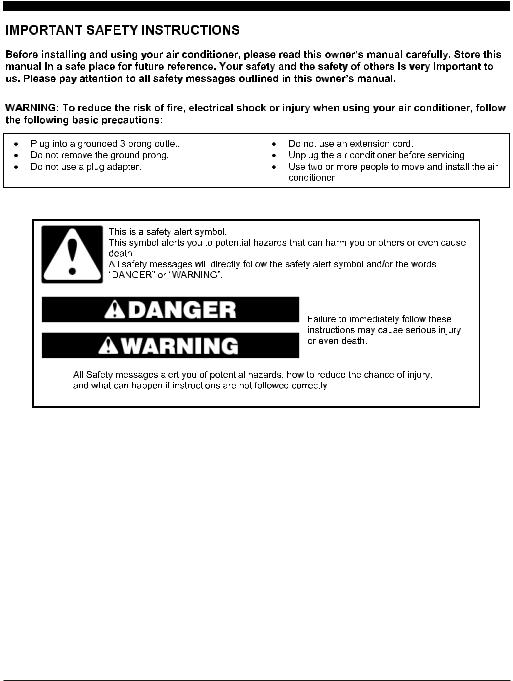
IMPORTANT SAFETY INSTRUCTION ........................................................................... |
1 |
ELECTRICAL REQUIREMENTS ................................................................................... |
2 |
PACKING LIST ............................................................................................................ |
3 |
INSTALLATION & ASSEMBLY INSTRUCTIONS .............................................................. |
4 |
USING YOUR AIR CONDITIONER ................................................................................ |
9 |
OPERATING YOUR AIR CONDITIONER ........................................................................ |
11 |
CARE AND CLEANING ................................................................................................ |
12 |
TROUBLESHOOTING ................................................................................................. |
13 |
1

8K/10K/12K-115V |
8K/10K/12K/14K |
10K/12K/14K-230V |
Cooling |
Cooling & Heating |
Cooling |
2
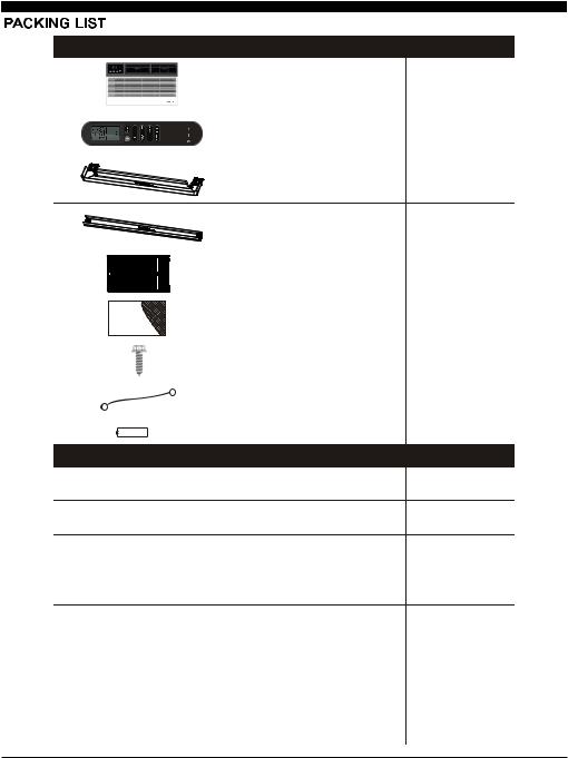
IMAGE |
PAPT |
QUANTITY |
|
Through-The-Wall Air Conditioner |
1 |
|
Remote Controll |
1 |
|
Trim Frame 1 (Left&Right legs) |
2 |
|
Trim Frame 2 (Top&Bottom legs) |
2 |
|
Grille Aluminum |
1 |
|
Rear plastic net |
1 |
|
1/2" Long Hex-head Screw |
4 |
|
Grouding wire with tooth washer |
1 |
|
Battery |
2 |
Dimension |
PAPT |
QUANTITY |
1’’x3/4’’x14’’ |
Seal sponge |
2 |
1’’x3/8’’x14’’ |
Seal sponge |
2 |
1’’x3/8’’x25’’ |
Seal sponge |
3 |
1’’x1 1/2’’x25’’ |
Seal sponge |
3 |
1’’x1 1/2’’x14’’ |
Seal sponge |
2 |
1’’x1 1/2’’x84’’ |
Seal sponge |
1 |
3 3/4’’x1 1/2’’x4’’ |
Seal cotton |
4 |
3/4’’x1 1/2’’x17’’ |
Seal cotton |
2 |
3
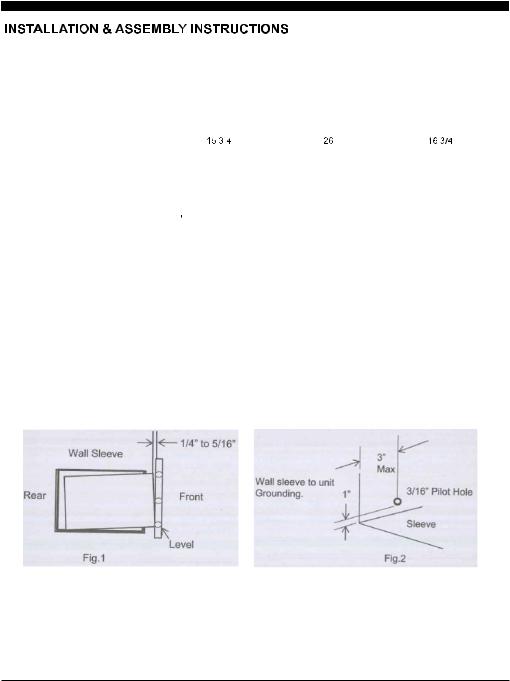
Universal Wall-Sleeve Dimensions
1. Identify the wall-sleeve brand for your preparing, from the below chart.
Type |
|
Wall-sleeve Dimensions |
|
|
Height |
|
Width |
Depth |
|
|
|
|||
Standard Dimension |
’’ |
|
’’ |
’’ |
|
|
|
|
|
NOTE
•All wall sleeves used to mount the new air conditioner must be in sound structural condition andhave a rear grille that securely attached tothe sleeve, or rear flange that serves as a stop for the air conditioner.
•


•


CAUTION
When installation is complete, replacement unit must have rearward slope as shown in Fig 1.
2.Remove old Air Conditioner from wall sleeve and prepare as followings:
--- Clean interior (Do not disturb seals).
--- Check the wall sleeve be securely fastened in wall before installing. Add more nails or screws if needed.
--- Repair painted surface if needed.
3.If the ground wire hole does not exist, drill a 3/16'' pilot hole for the grounding screw through the left hand side of the sleeve, in a clear area about 3 inches max. back from the front edge as below. Pull the loose end of the ground wire out of the front of the sleeve and bend it away from the opening. This will be attached to the air conditioner once installed.
4.Install new unit into wall sleeve.
5.To attach ground wire to the new unit, remove the screw from the left side front.
6.Assemble and install the Trim Frame.
4
NOTE
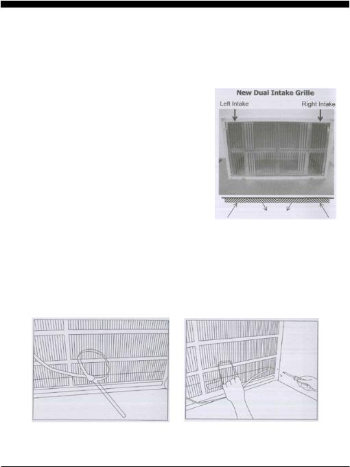
• This unit´s increased performance characteristics is the result of having two rear intakes.
•It is very important that these installation instructions are followed so your unit can operate at maximum efficiency.
•If there is an existing sleeve and rear grille, please check whether the dimension is suitable or not, otherwise replace them.
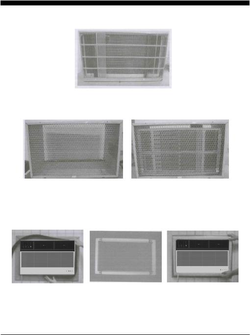
Existing Frigidaire sleeves may have older single-sided intake grilles, as below pictures show.
1. These grilles should be replaced with the dual intake grille type, as shown in the pictures below.
• Remove the existing grille and save the mounting screws.
•Place the grille included with your new air conditioner towards the inside rear of the sleeve.
• Attach the new grille by aligning the four mounting holes.
• Re-insert the self-tapping screws into the nylon retainers.
2. Grille Removal
Important: Single intake grille must be removed when used with dual intake TTW unit.
Warning: When removing grille, protect it from falling by securing with a leash. This can be fastened from cord or strapping looped through the grille and secured with a knot.
While holding the grille by the leash with one hand, the retaining screws can be removed and the grille can be brought inside through the front of the sleeve.
5
Direct Unit Mounting
In case where the dual intake grille cannot be mounted directly to the sleeve it is desirable to attach the grille to the back of the TTW unit to the hole predrilled in the unit.
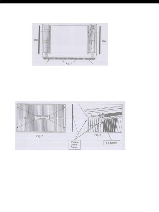
1. Attach the 2 seals(1''x3/8''x14''), as shown in Fig. 1.
2. Position the grille over the rear of the unit making sure that: a.The double set of screw holes are at the bottom.
b.The intake fins on either side are pointed away from the unit.
3. Align the top of the grille with the top of the unit. The overhang on each side is equal.
4.If the unit has not been predrilled (some models), carefully drill 4-1/8'' holes through the grille and into the side flange of the unit approximately 1 1/2'' to 2'' from the top and bottom, as Fig. 2 and 3 show. (Be careful not to break the copper pipe)
5.Install 4-#8 self-tapping screws to affix the grille to the unit.
6.Insert the unit into the sleeve.
Grille to Sleeve Attachment
In case where the dual intake grille fits inside the sleeve and the grille flange overlaps the sleeve flange, direct attachment may be possible.
IMPORTANT
If the suitable grille is not used, it may lead to product damage and possible failure.
6
Seal Installation
1. 1''x3/8''x25'' long seal in the center at the top of the sleeve. Remove the back paper and press into position.
2.1''x3/8''x14'' seals to the left and right sides of the sleeve.
3.Cut 1''x3/8''x25'' long seals to 14'' long each and attach to the vertical sections of the grille as shown.
4.1/2''x3 1/2''x1 1/2'' centering blocks one on each side wall. Place in center of side wall with the tapered end facing the opening.
5.Gently slide unit into sleeve.
Ground Wire Installation
1.Install screw end of ground wire into inside of sleeve according to preparation instruction.
2.Before sliding unit all the way back remove second screw from left side of unit.
3.Remove plastic washer from screw.
4.Screw the other end of the ground wire into the unit as shown. Make sure the toothed washer is against the cabinet.
5.Slide unit completely to the rear.
Non-Frigidaire Dual Intake Grille
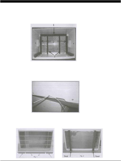
In case where the existing sleeve is a non-Frigidaire sleeve but is installed with a dual intake grille, the existing. grille may be left in place. Make sure the outer 3 1/2'' to 4 1/2'' louvers are angled from the left and right sides of the sleeve toward the center, as Fig. 1 shows. This provides proper flow of outside air into the unit.
From the installation kit, apply two 1''x3/4''x14'' seals along the flat metal flange of the condenser, as Fig. 2 shows.
7
Insert the unit with the seal into the sleeve pushing it all the way to the rear, making sure the seals are against the rear grille. The seals are necessary to reduce recirculation of hot air into the intakes which would reduce system performance.
An option is to purchase 3/4'' diamond cut aluminum grille and cut it to fit inside the sleeve. Secure it with screws. Attach the dual intake grill directly to the back of the unit. Slide the entire unit into the sleeve and seal with the stuffing seal supplied with the kit.
Trim Kit Installation Instructions
1.Install the 1''x1''x84'' long stuffer seal between the wall sleeve and the unit. A flat-bladed screwdriver or putty knife is needed.
2.Assemble the trim frame by inserting the top and bottom pieces into side pieces and snapping into place.
3.Pull the cord through the trim frame and slide the trim over the unit until flush with the wall.
Energy saving suggestion: In order to reach the maximum energy saving and comfortability, it is necessary to use an appropriately sized cover to provide additional insulation and air sealing when the unit is not in use during the off-using-season.
8
For Cooling model |
1 |
2
3
9 |
8 |
7 |
6 |
5 |
4 |
For Heating model |
|
1 |
|
|
|
2
3
9 8 7 6 5 4
1.Digital Display: Without timer setting, the set temperature will be displayed.
Time will be displayed under the timer setting.
2.+ and - Button: Use these buttons on the control panel and remote to increase or decrease
the Set Temperature or Timer.
Temperature range: 61 ~88
~88 or 16
or 16 ~31
~31 .
.
3.  Button: Turn the air conditioner on and off.
4.Mode Button: Press the mode button to cycle through the various modes: Cool, Dry, Fan and Auto, or Heat.
Cool Mode: The cooling function allows the air conditioner to cool the room and at the same time reduces air humidity. Press the MODE button to activate the cooling function. To optimize the function of the air conditioner, adjust the temperature and the speed by pressing the button indicated.
Dry Mode: This function reduces the humidity of the air to make the room more comfortable. Press MODE button to set the DRY mode. An automatic function of alternating cooling cycles and air fan is activated.
Fan Mode: The conditioner works in only ventilation. Press MODE button to set the FAN mode. With pressing the FAN SPEED button the speed changes in the following sequence: Hi, Med and Lo in FAN mode.
Auto Mode: In AUTO mode the unit automatically chooses the fan speed and the mode of operation (COOL,HEAT,DRY or FAN). In this mode the temperature are set automatically according to the room temperature (tested by the temperature sensor which is incorporated in the indoor unit.). Heat Mode: The heating function allows the air conditioner to heat the room. Press the MODE button to activate the heating function. To optimize the function of the air conditioner, adjust the temperature and the speed by pressing the button indicated.
5.Timer Button: Use these buttons on the control panel and remote to set the Timer.
Timer Off: The timed stop is programmed by pressing TIMER button. Set the rest time by
pressing the button + or - until the rest time displayed is to your liking then press
the TIMER button again.
Timer On: When the unit is off, press TIMER button at the first time, set the temperature with
pressing the button + or - . Press TIMER
button at the second time, set the rest time with pressing the button + or - . Press TIMER
button at the third time, confirm the setting, then the rest time to next automatical switching-on could be read on the display of the machine.
Note: It can be set to automatically turn off or on in
0.5-24 hours. Each press of the + -
buttons will increase or decrease the timer. The
Timer can be set in 0.5 hours increment below 10 hours and 1 hour increment for 10 hours or above. The SET light will turn on while setting.
To cancel the set function, press the TIMER button again.
9
 Loading...