


Installation & Operation Guide
Thru-the-Wall Series
115 Volts  UE08
UE08
230 Volts  UE10
UE10  UE12
UE12
Model information can be found on the name plate on the front of the unit.
To register your application, complete and mail the enclosed registration card, or register on-line at www.friedrich.com (USA only).
For your future convenience, record the model information here.
MODEL NUMBER |
SERIAL NUMBER |
PURCHASE DATE |
920-136-01(01/05)
Before you call for service... Parts and Installation Operating Instructions Electrical Data Safety Precautions
Safety Precautions
Safety Precautions ............. |
3 |
Electrical Data |
|
Electrical Data .................... |
5 |
Operating Instructions
Controls.............................. |
6 |
Ventilation Control.............. |
8 |
Air Direction........................ |
8 |
Care and Maintenance
Air Filter Cleaning |
...............9 |
How to Attach Front Grille |
|
to Cabinet........................... |
9 |
Parts and Installation |
|
Parts.................................... |
10 |
Installation ............................. |
11 |
How to Install ...................... |
11 |
Procedure......................... |
13 - 17 |
Before you call |
|
for service... |
|
Trouble Shooting Tips |
.......18 |
Normal Operation .............. |
18 |
Abnormal Operation .......... |
18 |
Warranty ........................... |
19 |
READ THIS MANUAL
Inside you will find many helpful hints on how to use and maintain your air conditioner properly. Just a little preventive care on your part can save you a great deal of time and money over the life of your air conditioner.
You'll find many answers to common problems in the trouble shooting section. First review the trouble shooting section before calling service. Your question may already be answered.
CAUTION
•Contact an authorized Service technician for repair or maintenance of this unit.
•The air conditioner is not intended for use by young children without supervision.
2
Safety Precautions
To prevent injury and property damage, the following instructions must be followed.
■Ignoring instructions and incorrectly operating the unit can cause harm or damage. The seriousness is classified by the following indications.
 WARNING : This symbol indicates the possibility of death or serious injury.
 CAUTION : This symbol indicates the possibility of injury or damage to property only.
■ Meanings of symbols used in this manual are as shown below.
Never do this.
Always do this.

 WARNINGI
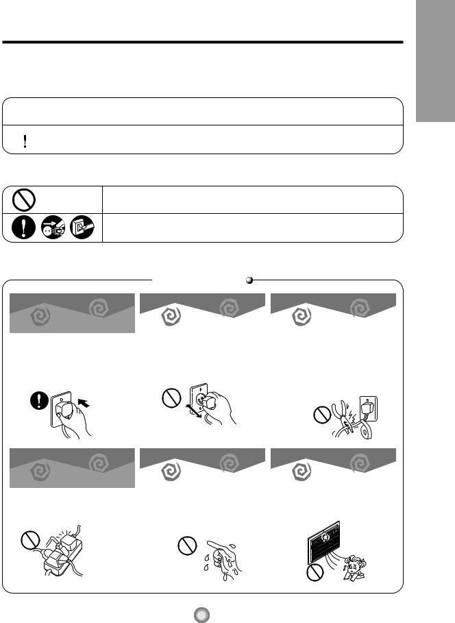
Plug in the power plug properly.
•Otherwise, it will cause electric shock or fire due to heat generation.
Do not modify power cord length or share the outlet with other appliances.
•It will cause electric shock or fire due to heat generation.
Do not operate or stop the |
|
Do not damage or use an |
unit by inserting or pulling |
|
unspecified power cord. |
out the power plug. |
|
|
|
|
|
• It will cause electric shock or fire |
• It will cause electric shock or fire. |
|
due to heat generation. |
• If the power cord is damaged, it |
|
|
|
must be replaced by the |
|
|
manufacturer or an authorized |
|
|
service center. |
Do not operate with wet |
|
Do not direct airflow directly |
hands or in damp |
|
at room occupants. |
environment. |
|
|
|
|
|
• It will cause electric shock. |
• This could harm your health. |
|
Precautions Safety
3
Safety Precautions
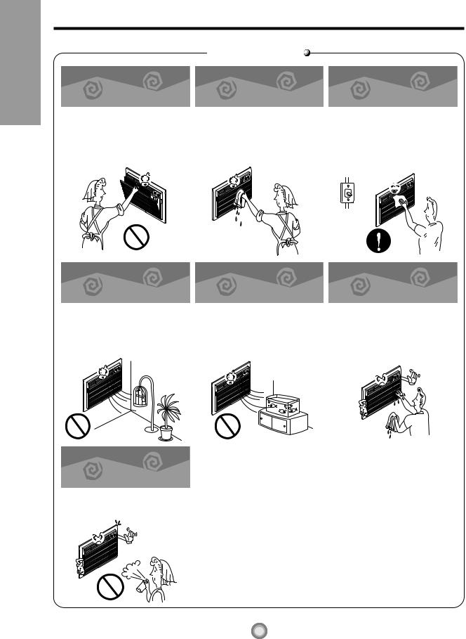
When the air filter is to be removed, do not touch the metal parts of the unit.
•They are sharp and may cause an injury.
Do not put a pet or house plant where it will be exposed to direct air flow.
•This could harm the pets or plants.
Do not apply an insecticide or flammable spray.
•It may cause a fire or damage the cabinet.

 CAUTIONI
Do not clean the air conditioner with water.
•Water may enter the unit and damage the insulation.
Do not use for special purposes.
When the unit is to be cleaned, switch off, and turn off the breaker.
•Since the fan rotates at high speed during operation, it may cause an injury.
Do not operate switches with wet hands.
• Do not use this air conditioner to |
• It may cause an electric shock. |
preserve precision devices, |
|
food, pets, plants, and art |
|
objects. It may cause |
|
deterioration of quality, etc. |
|
4
Electrical Data
Electrical |
Data |
|
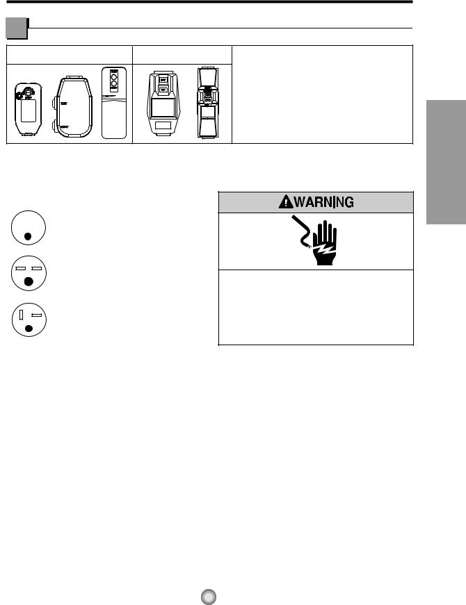
115V~ |
230V~ |
Power cord may include a current interrupter |
|
|
device. A test and reset button is provided on the |
|
|
plug case. The device should be tested on a |
|
|
periodic basis by first pressing the TEST button |
|
|
and then the RESET button. If the TEST button |
|
|
does not trip or if the RESET button will not stay |
|
|
engaged, discontinue use of the air conditioner and |
|
|
contact a qualified service technician. |
USE OF EXTENSION CORDS
Because of potential safety hazards, do not use an extension cord.
|
|
Use Wall Receptacle |
Power Supply |
|||||
|
|
|
|
|
|
|
|
|
|
|
|
|
|
|
|
Standard 125V, |
|
|
|
|
|
|
|
|
3-wire grounding |
|
|
|
|
|
|||||
|
|
|
|
|
|
|
receptacle rated |
Use 15 AMP. time |
|
|
|
|
|
|
|
15A, 125V AC |
|
|
|
|
|
|
|
|
delay fuse or 15 AMP. |
|
|
|
|
|
|
|
|
|
|
|
|
|
|
|
|
|
|
|
|
|
|
|
|
|
|
Standard 250V, |
circuit breaker. |
|
|
|
|
|
|
|
3-wire grounding |
|
|
|
|
|
|
|
|
|
|
|
|
|
|
|
|
|
receptacle rated |
|
|
|
|
|
|
|
|
15A, 250V AC |
|
|
|
|
|
|
|
|
|
|
|
|
|
|
|
|
|
Standard 250V, |
Use 20 AMP. time |
|
|
|
|
|
|
|
3-wire grounding |
|
|
|
|
|
|
|
|
delay fuse or 20 AMP. |
|
|
|
|
|
|
|
|
receptacle rated |
|
|
|
|
|
|
|
|
circuit breaker. |
|
|
|
|
|
|
|
|
20A, 250V AC |
|
|
|
|
|
|
|
|
|
|
|
|
|
|
|
|
|
|
|
Electrical Shock Hazard
Plug into a grounded 3 prong outlet. Do not remove ground prong.
Do not use an adapter.
Do not use an extension cord.
Failure to follow these instructions can result in death, fire, or electrical shock.
All wiring should be done in accordance with local electrical codes and regulations.
NOTE : Aluminum house wiring may pose special problems. Consult a qualified electrician.
■  ELECTRICAL SAFETY
IMPORTANT GROUNDING INSTRUCTIONS
The air conditioner has a three-prong grounding plug on its power supply cord, which must be plugged into properly grounded three-prong wall receptacle for your protection against possible shock.
FUSE – Use a time-delay fuse or circuit breaker. Refer to the nameplate for proper power supply requirements.
208/230 VOLT UNITS
These units are equipped with a three-prong grounding plug on the power supply cord, which must be plugged in to a matching, properly grounded three-prong wall receptacle for your protection against possible shock hazard. If such an outlet is not present, one must be installed by a qualified electrician in accordance with the National Electrical Code and local codes and ordinances.
Data Electrical
5
Operating Instructions
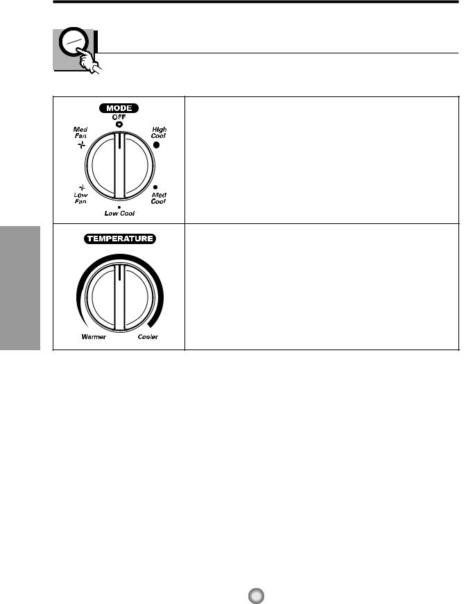
The controls will look like one of the following:
Controls – Cooling Only Models
Operating Instructions
Off |
- Turns air conditioner off. |
Med Fan Only |
- Med speed fan operation without cooling. |
Low Fan Only |
- Low speed fan operation without cooling. |
High Cool |
- Cooling with high speed fan operation. |
Med Cool |
- Cooling with med speed fan operation. |
Low Cool |
- Cooling with low speed fan operation. |
This automatically controls the temperature of the indoor air.
Turn the knob clockwise for greater cooling.
Turn the knob counter-clockwise for more moderate cooling.
• FOR NORMAL COOLING
1. Turn the MODE Knob to the Med Cool setting.
2. Set the Temperature Knob to the desired temperature (the mid-point is a good starting position).
If the room temperature is not satisfactory after a reasonable time, adjust the control to a cooler or warmer setting, as appropriate.
• FOR MAXIMUM COOLING
1.Turn the MODE Knob to the High Cool setting.
2.Set the Temperature Knob to the coolest temperature setting all the way to the right.
• FOR QUIETER OPERATION
1.Turn the Operation Knob to the Low Cool setting.
2.Set the Temperature Knob as needed.
6
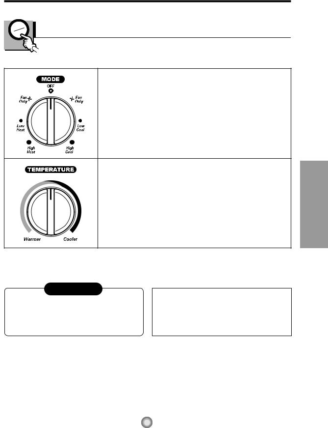
The controls will look like one of the following:
Controls – Cooling & Heating
Off |
- Turns the air conditioner off. |
Fan Only |
- The low fan speed operation without cooling/heating. |
Low Cool |
- Cooling with the low speed fan operation. |
High Cool |
- Cooling with the high speed fan operation. |
Low Heat |
- Heating with the low speed fan operation. |
High Heat |
- Heating with the high speed fan operation. |
Turn the Temperature Knob to the desired setting. The central position is a normal setting for average conditions. You can change this setting, if necessary, in accordance with your temperature preference.
The thermostat automatically controls cooling or heating, but the fan runs continuously whenever the air conditioner is in operation. If the room is too warm, turn the thermostat control clockwise. If the room is too cool, turn the thermostat control counterclockwise.
The compressor will turn on and off to keep the room at the set temperature.
In the heating operation, the electric heater will turn on and off to keep the room at the set temperature.
CAUTION
When the air conditioner has been operated in the cooling or heating mode and is turned off or set to the fan position, wait at least 3 minutes before resetting to the cooling operation again.
A slight burning odor may come from the unit when first switching to HEAT after the cooling season is over. This odor, caused by fine dust particles on the heater, will disappear quickly. This is normal operation.
Instrucitons Operating
7
Operating Instructions
Additional controls and important information.
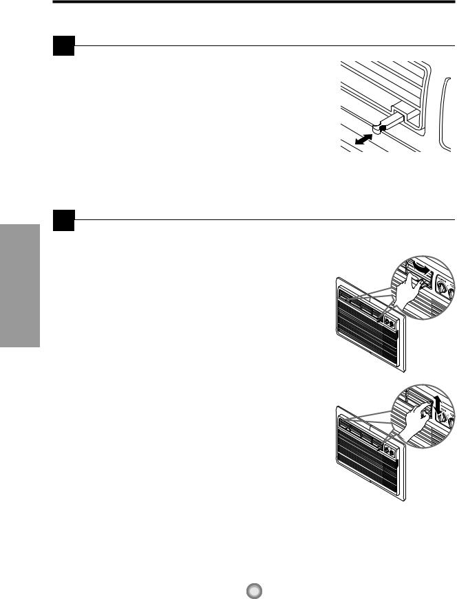
 Ventilation Control
Push the lever to the "CLOSE" position to cool, heat or recirculate room air only.
Pull the lever to the "OPEN" position to exhaust smoke or stale air from the room.
This feature is best used in conjunction with the FAN ONLY position.
PULL OPEN / PUSH CLOSE
 Air Direction
The direction of air can be controlled by adjusting the horizontal and vertical louvers.
• HORIZONTAL AIR-DIRECTION CONTROL
The horizontal air direction is adjusted by moving the vertical louver. The lever for the vertical louver is located in the right and left side of the air discharge.
• VERTICAL AIR-DIRECTION CONTROL
The vertical air direction is adjusted by moving the horizontal louver.
8
Care and Maintenance
TURN THE AIR CONDITIONER OFF AND REMOVE THE PLUG FROM THE POWER OUTLET.
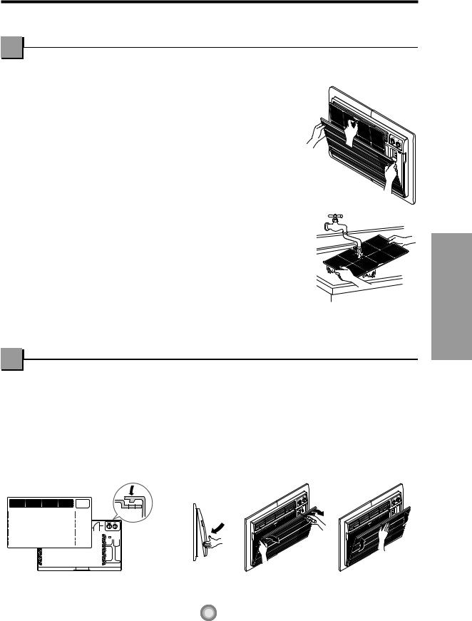
Air Filter Cleaning
The air filter should be checked at least twice a month to see if cleaning is necessary. Trapped particles in the filter will build up and block the airflow. This reduces the cooling capacity and can also cause an accumulation of frost on the cooling coils.
If the filter becomes torn or damaged you should replace it immediately. Replacement filters are available from your salesperson, dealer, and authorized customer service centers.
1. Open the inlet grille downward by grasping the top outside edges of the inlet grille and pulling it towards you.
2. Remove the air filter from the front grille assembly by pulling the air filter up slightly.
3. Wash the filter using lukewarm water and a mild detergent.
4. Gently shake all excess water from the filter.
Make sure the filter is completely dry and replace the filter back into the unit.
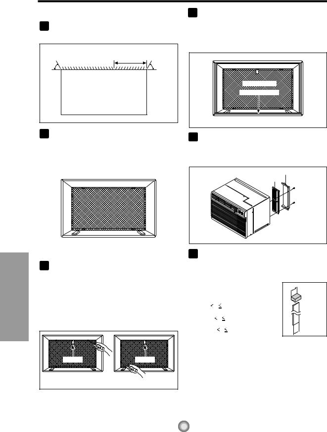
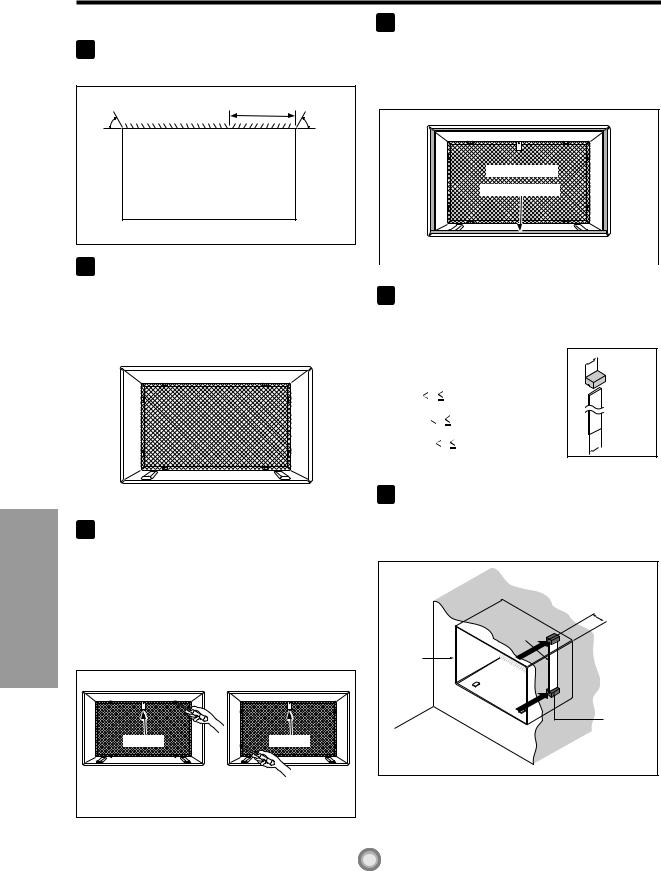
How to Attach Front Grille to Cabinet
The front grille can be removed for cleaning or to check the model and serial numbers. For your safety, you should attach the front grille using the following procedures.
|
1. |
Pull down front grille from the cabinet |
3. |
Open the inlet grille. |
||||||||||||||
|
|
|
top. |
4. |
Tighten the screw through the front grille |
|||||||||||||
|
2. |
Push front grille’s tips toward the cabinet |
|
into the plate of control box. |
||||||||||||||
|
|
|
in order to insert front grille’s tabs into |
5. |
Close inlet grille. |
|||||||||||||
|
|
|
the cabinet. |
|
|
|
|
|
|
|||||||||
|
|
|
|
|
|
|
|
|
|
|
|
|
|
|
|
|
|
|
|
|
|
|
|
|
|
|
|
|
|
|
|
|
|
|
|
|
|
|
|
|
|
|
|
|
|
|
|
|
|
|
|
|
|
|
|
|
|
|
|
|
|
|
|
|
|
|
|
|
|
|
|
|
|
|
|
|
|
|
|
|
|
|
|
|
|
|
|
|
|
|
|
|
|
|
|
|
|
|
|
|
|
|
|
|
|
|
|
|
|
|
|
|
|
|
|
|
|
|
|
|
|
|
|
|
|
|
|
|
|
|
|
|
|
|
|
|
|
|
|
|
|
|
|
|
|
|
|
|
|
|
|
|
|
|
|
|
|
|
|
|
|
|
|
|
|
|
|
|
|
|
|
|
|
|
|
|
|
|
|
|
|
|
|
|
|
|
|
|
|
|
|
|
|
|
|
|
|
|
|
|
|
|
|
|
|
|
|
|
|
|
|
|
|
|
|
|
|
|
|
|
|
|
|
|
|
|
|
|
|
|
|
|
|
|
|
|
|
|
|
|
|
|
|
|
|
|
|
|
|
|
|
|
|
|
|
|
|
|
|
|
|
|
|
|
|
|
|
|
|
|
|
|
|
|
|
|
|
|
|
|
|
|
|
|
|
|
|
|
|
|
|
|
|
|
|
|
|
|
|
|
|
|
|
|
|
|
|
|
|
|
|
|
|
|
|
|
|
|
|
|
|
|
Instrucitons Operating
9
Parts
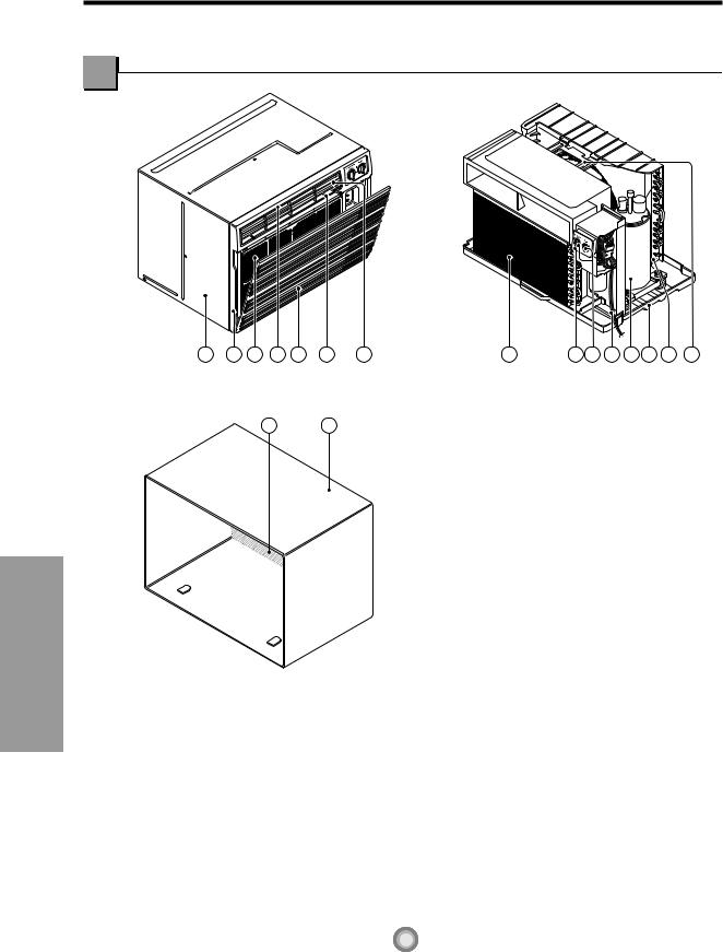
Learning part name prior to installation will help you understand the installation procedure.
Parts
The Unit
1 |
5 |
7 |
3 |
6 |
2 |
4 |
11 |
8 |
9 |
10 13 14 12 |
15 |
The Sleeve with the Rear Grille (sold separately)
17 16
Parts and Installation
1.CABINET
2.HORIZONTAL AIR DEFLECTOR (Vertical Louver)
3.VERTICAL AIR DEFLECTOR (Horizontal Louver)
4.AIR DISCHARGE
5.FRONT GRILLE
6.INLET GRILLE (Air Intake)
7.AIR FILTER
8.CONTROL BOARD
9.BUTTONS
10.POWER CORD
11.EVAPORATOR
12.CONDENSER
13.COMPRESSOR
14.BASE PAN
15.BRACE
16.SLEEVE ASSEMBLY
(Including Expanded Aluminum Rear grille)
17.REAR GRILLE
10
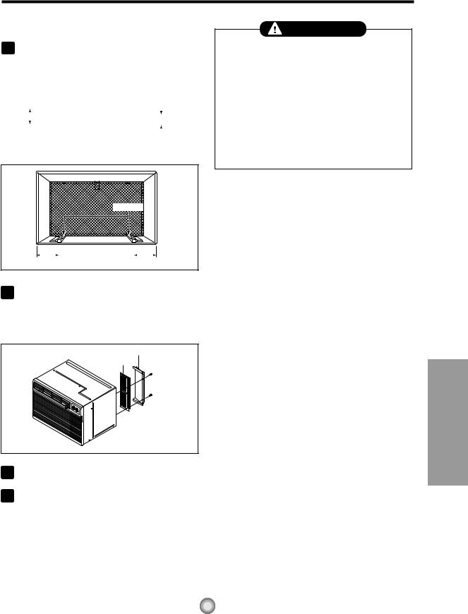
Installation
Remove packing sheet from the back of the sleeve, and packing corner and blue tape from the air conditioner.
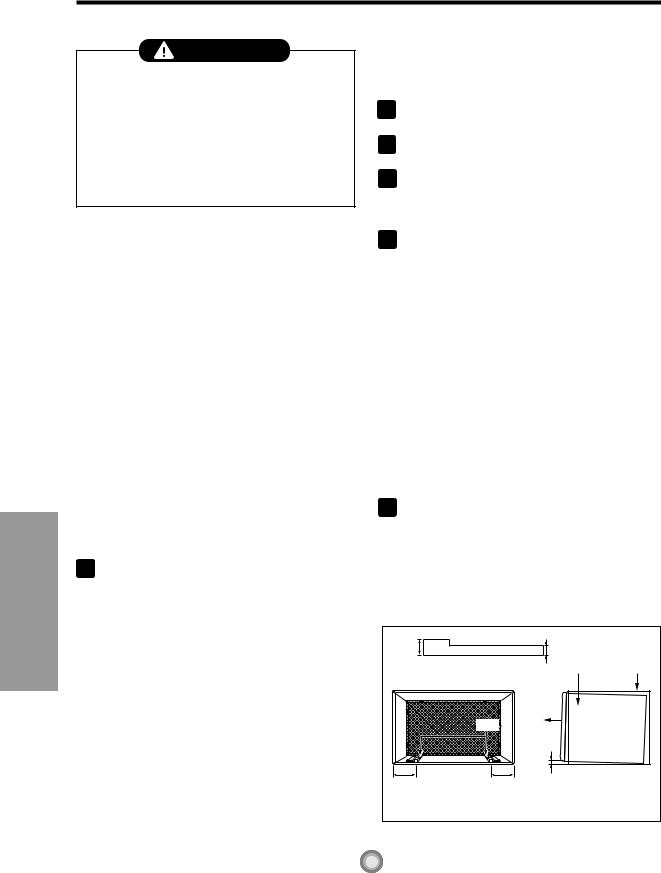
INSTALLATION REQUIREMENTS
If you use an existing wall sleeve, you should measure its dimensions.
Install the new air conditioner according to these installation instructions to achieve the best performance. All wall sleeves used to mount the new air conditioner must be in good structural condition and have a rear grille to securely attach the new air conditioner. (FIG. 1) Installing the FRIEDRICH USC sleeve ensures optimal performance of the new air conditioner. (FIG. 2)
19-21/32"
(499 mm) 24-21/32"
(626 mm)
14-13/32"
(366 mm)
|
18"(458 mm) |
Air Conditioner |
FIG. 1 |
|
25-7/8" |
|
(656 mm) |
|
15-17/32" |
|
(394 mm) |
aluminum metal grille |
|
|
16-23/32" |
|
(425 mm) |
FRIEDRICH Wall Sleeve |
FIG. 2 |
ELECTRICAL SERVICE
Check your available electrical service. The power supply available must be the same as that shown on the unit nameplate (found on left side of cabinet).
All models are equipped with a 3-prong service plug to provide proper service and safe positive grounding. Do not change plug in any way. Do not use an adapter plug. If your present wall outlet does not match your plug, call a qualified electrician to make the necessary corrections. SAVE CARTON for storage and this OWNER'S MANUAL for future reference. The carton is the best way to store unit during winter or when not in use.
INSTALLATION HARDWARE
1 |
|
2 |
|
|
4 |
|
|
|
|
|
|
|
|
2 Size options |
9 |
|
7 |
5 |
|
|
|
||
|
|
|
|
8 |
|
3 |
|
|
|
6 |
|
|
|
2 Size options |
|
ITEM |
NAME OF PARTS |
Q'TY |
1 |
PLASTIC GRILLE |
1 |
2 |
HORIZONTAL INSULATION STRIPS |
2 |
3 |
AROUND INSULATION STRIPS |
2 |
4 |
SUPPORT BLOCK |
2 |
5 |
BAFFLE |
1 |
6 |
TRIM FRAME |
2 |
7 |
SHIM |
2 |
8 |
PLASTIC NUTS AND WASHER SCREWS |
4 |
9 |
GRILLE REAR |
1 |
|
|
|
CAUTION
To avoid risk of personal injury, property damage, or product damage due to the weight of this device and sharp edges that may be exposed:
•Air conditioners covered in this manual pose an excessive weight hazard. Two or more people are needed to move and install the unit.
To prevent injury or strain, use proper lifting and carrying techniques when moving unit.
•Carefully inspect location where air conditioner will be installed. Be sure it will support the weight of the unit over an extended period of time.
•Handle air conditioner with care. Wear protective gloves whenever lifting or carrying the unit. AVOID the sharp metal fins of front and rear coils.
•Make sure air conditioner does not fall during installation.
REQUIRED TOOLS:
• Tight Fitting gloves |
• 3/8-inch open end |
|
• Standard screwdriver |
wrench or adjustable |
|
wrench |
||
• Phillips screwdriver |
||
• 1/4-inch hex socket |
||
• Pliers |
||
and ratchet |
||
• Sharp knife |
||
• Tape measure |
||
|
||
|
• Electric drill |
|
|
• 1/4-inch drill bit |
Installation and Parts
11
Parts and Installation
INSTALLATION
CAUTION
Installing the FRIEDRICH USC sleeve ensures optional performances of the unit.
If you decide to keep the existing wall sleeve, you have to redirect the louvers at the back of the wall sleeve. Refer to FIG. 8 on p14. The use of pliers is recommended. If you DO NOT redirect, you run the risk of poor performance or premature product failure. This is not covered under the terms of the FRIEDRICH warranty.
•Pick a location which will allow the conditioned air to blow into the area you want. Good installation with special attention to the proper position of the unit will lessen the chance that service will be needed.
ITEMS IN INSTALLATION HARDWARE
You may not need all parts in the kit. Discard unused parts
ITEM |
DIMENSIONS(inches) |
Qty. |
|
Plastic grille |
263/4 x 161/2 |
1 |
|
Horizontal Insulation Strips |
13/8 x 5/8 x 273/16 |
1 |
|
13/8 x 13/8 x 273/16 |
1 |
||
|
|||
Around Insulation Strips |
13/8 x 3/4 x 611/2 |
1 |
|
13/8 x 13/8 x 611/2 |
1 |
||
|
|||
Support Block |
13/4 x 13/8 x 45/16 |
2 |
|
Baffle |
14 x 41/2 x 1/8 |
1 |
|
Shim |
13 x 1 x 3/4 |
2 |
|
Trim Frame |
|
2 |
|
Washer Screw |
|
4 |
|
Nuts(Plastic) |
|
4 |
|
Grille Rear |
|
1 |
HOW TO INSTALL 1
Brand |
Wall Sleeve Dimensions (inches) |
|||
Width |
Height |
Depth |
||
|
||||
White-Westinghouse |
|
|
16, 17-1/2 |
|
Frigidaire |
25-1/2 |
15-1/4 |
||
Carrier (52F series) |
|
|
or 22 |
|
|
|
|
||
General Electric |
26 |
15-5/8 |
16-7/8 |
|
/Hotpoint |
||||
|
|
|
||
Whirlpool |
25-7/8 |
16-1/2 |
17-1/8 |
|
or 23 |
||||
|
|
|
||
Fedders/Emerson |
27 |
16-3/4 |
16-3/4 |
|
Friedrich WSC |
or 19-3/4 |
|||
|
|
|||
FRIEDRICH USC |
25-7/8 |
15-17/32 |
16-23/32 |
|
Emerson/Fedders |
26-3/4 |
15-3/4 |
15 |
|
Carrier (51S Series) |
25-3/4 |
16-7/8 |
18-5/8 |
|
NOTE: All wall sleeves used to mount the new Air Conditioner must be in sound structural condition and have a rear grille that securely attaches to sleeve, or rear flange that serves as a stop for the Air Conditioner.
2 Removesleeve. old air conditioner from existing wall
Clean the interior of an existing sleeve. 3 (Do not disturb seals or gaskets.)
4 Wall sleeve must be securely fastened in wall before installing the air conditioner. Use the nails or screws through sleeve into wall, if needed. Repaint sleeve if needed.
5 Prepare the wall sleeve for installation of the unit. If you plan to use your existing wall sleeve, and it is not FRIEDRICH, use procedure B or C below.
Procedure |
Brand |
Depth(inches) |
|
A(page 13) |
FRIEDRICH USC |
16-23/32 |
|
|
White-Westinghouse |
16, 17-1/2 |
|
|
Frigidaire Carrier |
||
|
or 22 |
||
B |
(52F series) |
||
|
|||
General Electric |
|
||
(pages 14~15) |
16-7/8 |
||
|
/Hotpoint |
|
|
|
Whirlpool |
17-1/8 or 23 |
|
|
Carrier (51S series) |
18-5/8 |
|
C |
Fedders/Emerson |
16-3/4 |
|
Friedrich WSC |
or 19-3/4 |
||
(pages 16~17) |
|||
Emerson/Fedders |
15 |
||
|
|
|
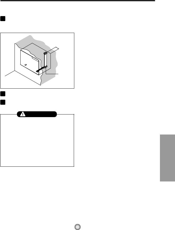
6 Install new unit into wall sleeve.
CAUTION: When installation is completed, replacement unit MUST have a rearward slope as
. To achieve 1/4" slope, remove the backing
shim to the front of the rib on base of wall sleeve.
1" high |
3/4" High |
|
|
UNIT |
Wall Sleeve |
Shim |
FRONT |
|
|
|
|
6" |
1/4" |
|
6" |
|
|
SHIM PLACEMENT |
UNIT INSTALLATION |
|
|
|
FIG. 3 |
12

PROCEDURE A
1 new sleeve (optionally unit),skip to step 3.
Otherwise, install the plastic grille from the kit. Cut the plastic grille to 25-1/2" wide and 15-1/4" high. Place the plastic grille to the inside of the wall sleeve at the rear flange.
FIG. 4
2 Fasten the 4 washer screws to secure the grille to the wall sleeve. If you need plastic nuts to mount plastic grille to the inside of the wall sleeve, there are plastic nuts in the installation kit. The nuts are installed from the inside of the sleeve and are pressing into the square holes of the rear flanges.Fasten the bracket to the upside of the wall sleeve using the washer screw. The bracket prevents the unit from leaving the sleeve.
Bracket |
|
Bracket |
the screws and the bracket |
or |
FIG. 5 |
3 Remove the backing from the Horizontal Insulation strip 13/8" x 5/8" x 27 3/16" and attach that to the inside bottom of the sleeve as shown below. Remove the backing from the Around Insulation strip 13/8" x 3/4" x 611/2" and attach that to the inside front of the sleeve as shown below.
Plastic rear grille
Steel rear grille
|
FIG. 7 |
5 |
Install the new unit into the wall sleeve. |
6 |
To assemble trim, snap the tab of each piece |
into the slot of the other piece as shown below. |
Slide trim over the front of the air conditioner until trim is flush with sleeve as shown below.
Trim (2 ea)
Wall
FIG. 8
 Around Insulation
Horizontal Insulation
FIG. 6
4 Remove the metal rear grille and replace it with the plastic rear grille to improve unit energy efficiency. The plastic grille reduces the amount of hot air discharge that recirculates through the unit.
CAUTION
•Air conditioners covered in this manual pose an excessive weight hazard. Two or more people are needed to move and install the unit.
To prevent injury or strain, use proper lifting and carrying techniques when moving unit.
•When handling the air conditioner, be careful to avoid cuts from sharp metal fins on front and rear coils.
•Make sure air conditioner does not fall during removal.
•If unit does not operate after installation check, to be sure the circuit interrupter has not been tripped. Refer to the Troubleshooting guide for reset procedure.
Installation and Parts
13
Parts and Installation
use of pliers is recommended.
|
7 3/32" |
60° |
60° |
|
Rear Louvers |
|
(Top View) |
|
FIG. 9 |
2 |
|
to step 4. If the wall sleeve does not have a rear grille or louvered panel, install the plastic grille from the kit. Cut the plastic grille to 25-1/2" wide and 15-1/4" high. Place the plastic grille to the inside of the wall sleeve at the rear flange.
Place the plastic grille |
FIG. 10 |
|
|
3 Fasten the 4 washer screws to secure the grille to the wall sleeve. If you need plastic nuts to mount plastic grille to the inside of the wall sleeve, there are plastic nuts in the installation kit. The nuts are installed from the inside of the sleeve and are pressed into the square holes of the rear flanges.Fasten the bracket to the upside of the wall sleeve using the washer screw. The bracket prevents the unit from leaving the sleeve.
Bracket |
Bracket |
Fasten the screws and the bracket |
or |
FIG. 11 |
4 Remove the backing from the Horizontal Insulation strip 13/8" x 5/8" x 27 3/16" and attach
sleeve as shown the Around
Insulation strip 13/8" x 3/4" x 611/2" and attach that to the inside front of the sleeve as shown below.
 Around Insulation
Horizontal Insulation
FIG. 12
5 Remove the metal rear grille and replace it with the plastic rear grille to improve unit energy efficiency. The plastic grille reduces the amount of hot air discharge that recirculates through the unit.
Plastic rear grille
Steel rear grille
FIG. 13
6 If the depth of your existing wall sleeve is less than or equal to 18", skip to step 7. Otherwise, cut the baffles and the support blocks according to length "A" in the table below.
Depth"D" of the existing |
Length "A" |
|
wall sleeve (inches) |
(inches) |
|
|
|
|
18 |
18-5/8 |
3/4 |
18-5/8 |
19-3/4 |
1-3/4 |
19-3/4 |
22 |
4 |
|
|
|
A
 Support
Block
 Baffle
A FIG. 14
14
PROCEDURE B CONTINUED 7
as shown FIG 15. Slide the baffle into slots of the support blocks.
(7 5/16")
Wall
Wall 


 Baffle
Front |
Support |
|
Block |
FIG. 15
8 Install the new unit into the wall sleeve.
9 |
as described in Step 6, |
|
CAUTION
•Air conditioners covered in this manual pose an excessive weight hazard. Two or more people are needed to move and install the unit.
To prevent injury or strain, use proper lifting and carrying techniques when moving unit.
•When handling the air conditioner, be careful to avoid cuts from sharp metal fins on front and rear coils.
•Make sure air conditioner does not fall during removal.
•If unit does not operate after installation check, to be sure the circuit interrupter has not been tripped. Refer to the Troubleshooting guide for reset procedure.
Installation and Parts
15
Parts and Installation
The use of pliers is recommended.
|
7 13/16" |
° |
60° |
60 |
|
|
Rear Louvers |
|
(Top View) |
|
FIG. 16 |
2 |
|
or louvered panel, install the plastic grille from the kit Cut the plastic grille to 26-1/2" wide and 15-1/2" high or to the sleeve dimensions. Place the plastic grille to the inside of the wall sleeve at the rear flange.
Place the plastic grille |
FIG. 17 |
|
|
3 Fasten the 4 washer screws to secure the grille to the wall sleeve. If you need plastic nuts to mount plastic grille to the inside of the wall sleeve, there are plastic nuts in the installation kit. The nuts are installed from the inside of the sleeve and are pressed into the square holes of the rear flanges. Fasten the bracket to the upside of the wall sleeve using the washer screw. The bracket prevents the unit from leaving the sleeve.
Bracket |
Bracket |
or |
|
Fasten the screws and the bracket |
FIG. 18 |
|
4 |
Remove the backing from the Horizontal |
|
Insulation strip 13/8" x 13/8" x 273/16" and attach |
Insulation strip 13/8" x 13/8" x 611/2" and attach that to the inside front of the sleeve as shown below.
 Around Insulation
Horizontal Insulation
|
FIG. 19 |
|
|
5 |
If the depth of your existing sleeve is less than |
|
or equal to 18”, skip to step 7. Otherwise, cut |
the baffles and the support blocks according to Length "A" in the table below.
Depth"D" of the existing |
Length "A" |
|
sleeve (inches) |
(inches) |
|
|
|
|
18 |
18-5/8 |
3/4 |
18-5/8 |
19-3/4 |
1-3/4 |
19-3/4 |
22 |
4 |
|
|
|
A
 Support
Block
 Baffle
A FIG. 20
6 Remove the backing from the support blocks and attach them to the inside of the wall sleeve as shown FIG 21. Slide the baffle into slots of the support blocks
Wall |
(7 13/16") |
|
Baffle |
||
|
||
Wall |
|
|
Sleeve |
|
|
Front |
Support |
|
|
Block |
|
|
FIG. 21 |
16
PROCEDURE C CONTINUED
7 |
Remove the backing from the 13" shim strips |
|||||||||||
and attach them as shown below in Fig. 22. |
||||||||||||
|
||||||||||||
|
The higher portion of shim is to be placed in |
|||||||||||
|
front of the rib on the base of wall sleeve. |
|||||||||||
|
|
|
|
|
|
|
|
|
|
|
||
|
|
|
|
|
|
|
|
|
|
|
|
|
1" high |
|
|
|
|
|
|
|
3/4" High |
||||
|
|
|
|
|
||||||||
|
|
|
|
|
|
|
|
|
|
|
||
|
|
|
|
|
|
|
|
|
|
|
||
|
|
|
|
|
|
|
|
|
FIG. 22 |
|||
|
|
|
|
|
|
|
|
|
|
|
|
|
|
|
|
|
|
|
|
|
|
|
|
|
|
|
|
|
|
|
|
|
|
|
|
|
|
|
Shim (2EA)
6" |
|
|
6" |
|
|
|
|
|
|
FIG. 23
metal rear grille and replace it with grille to improve unit energy
efficiency. The plastic grille reduces the amount of hot air discharge that recirculates through the unit.
Plastic rear grille
Steel rear grille
FIG. 24
Install the new unit into the wall sleeve
Assemble trim as described in Step 6,
Procedure A.
CAUTION
•Air conditioners covered in this manual pose an excessive weight hazard. Two or more people are needed to move and install the unit.
To prevent injury or strain, use proper lifting and carrying techniques when moving unit.
•When handling the air conditioner, be careful to avoid cuts from sharp metal fins on front and rear coils.
•Make sure air conditioner does not fall during removal.
•If unit does not operate after installation check, to be sure the circuit interrupter has not been tripped. Refer to the Troubleshooting guide for reset procedure.
17
Installation and Parts
Before you call for service...
Before you call for service...
Trouble Shooting Tips
Troubleshooting Tips Save Time and Money!
Review the chart below first and you may not need to call for service.
Normal Operation
•You may hear a pinging noise caused by water being picked up and thrown against the condenser on rainy days or when the humidity is high. This design feature helps remove moisture and improve efficiency.
•You may hear the thermostat click when the compressor cycles on and off.
•Water will collect in the base pan during high humidity or on rainy days. The water may overflow and drip from the outdoor side of the unit.
•The fan may run even when the compressor does not.
 Abnormal Operation
Problem |
Possible Causes |
What To Do |
|
|
|
|
|
|
■ The air conditioner is |
• Make sure the air conditioner plug is pushed |
|
|
unplugged. |
completely into the outlet. |
|
Air conditioner |
■ The fuse is blown/circuit |
• Check the house fuse/circuit breaker box and |
|
breaker is tripped. |
replace the fuse or reset the breaker. |
|
|
does not start |
|
||
|
■ Power failure. |
• If power failure occurs, turn the mode control to OFF. |
|
|
|
When power is restored, wait 3 minutes to restart the |
|
|
|
air conditioner to prevent tripping of the compressor |
|
|
|
overload. |
|
■The current interrupter • Press the RESET button located on the power cord device is tripped. plug, If the RESET button will not stay engaged,
discontinue use of the air conditioner and contact a qualified service technician.
■ Airflow is restricted. • Make sure there are no curtains, blinds, or furniture blocking the front of the air conditioner.
Air conditioner does not cool as it should
■The THERMOSTAT may • Turn the knob to the coolest temperature setting to the not be set high enough. right. The cooler setting provides maximum cooling.
■The air filter is dirty. • Clean the filter at least every 2 weeks.
|
See the operating instructions section. |
■ The room may have been |
• When the air conditioner is first turned on, |
hot. |
you need to allow time for the room to cool down. |
■ Cold air is escaping. |
• Check for open furnace floor registers |
|
and cold air returns. |
|
• Set the air conditioner's vent to the closed position. |
■ Cooling coils have iced up. • See Air Conditioner Freezing Up below.
Air conditioner |
■ Ice blocks the air flow and |
• Set the mode control at Med Fan or High Cool with |
freezing up |
stops the air conditioner |
the thermostat towards the left. |
|
from cooling the room. |
|
|
|
|
|
|
18 |
 Loading...