


El36n35b-a
Friedrich El36n35b-a, Sl28n30b-a, Sl24n30c-a, Sl28n30c-a, Sl24n30b-a Owner's Manual
...
SYSTEM FAN MODE
SCHEDULEFAN SPEED
AUTO
AUTO
AUTO
CONTINUOUS
°F°C
2012 Service/Parts Manual
93001402_00
Service Manual
Service Manual
Room Air Conditioners
Room Air Conditioners
AUTO FAN
CONTINUOUS
AUTO
F
C
SYSTEM
FAN MODE
POWER
FAN SPEED
SCHEDULE
Standard Chassis Models
Standard Chassis Models
Cool Only
Cool Only
115 -Volt:
115-Volt:
208-230-Volt:
208-230-Volt:
Cool
208-230-Volt: ES12N33*, ES15N33*, EM18N34*, EM24N34*, EL36N35*
208-230-Volt:
Electric Heat
208-230-Volt: YS12N33*, YM18N34*, YL24N35*
208-230-Volt:
Heat Pump
115 -Volt:
115-Volt: YS10N10*
Kuhl-Serv/PartsMan (9-12) *Last character may vary
SS08N10*, SS10N10*, SS12N10*, SS14N10*, SM15N10*
SS08M10, SS10M10, SS12M10, SS14M10
SS12N30*, SS15N30*, SM18N30*, SM21N30*
SS12M30, SS15M30, SM18M30, SM21M30
SM24N30*,SL22N30*, SL24N30*, SL28N30*, SL36N30*
Cool with Electric Heat
Cool with Electric Heat
Heat Pump with Electric Heat
Heat Pump with Electric Heat
Heat Pump
Heat Pump

Table Of Contents
Important Safety Information ..................................................................................................................................... 2-4
Introduction ................................................................................................................................................................... 5
Model and Serial Number Location .............................................................................................................................. 5
Unit Identication .......................................................................................................................................................... 6
Performance Data and Specications .......................................................................................................................... 7
Installation Information/Sleeve Dimensions/Circuit Rating ........................................................................................... 8
Electrical Data ............................................................................................................................................................... 9
Before Operating the Unit ............................................................................................................................................10
Kuhl Control Options ....................................................................................................................................................11
Control Panel and Display Identication ......................................................................................................................12
Control Panel Operation Instructions ......................................................................................................................13-19
Remote Control Operation ...................................................................................................................................... 20-21
Unit Operation ............................................................................................................................................................ 22
Electronic Control Sequence of Operation ............................................................................................................ 23-27
Fan Operation ............................................................................................................................................................. 28
Removing the Front Cover and Unit Chassis ................................................................................................................ 29
Replacing the ID Coil Thermistor ................................................................................................................................ 30
Replacing the Control Board ....................................................................................................................................... 30
Airow Selection and Adjustment ............................................................................................................................... 31
Components Testing .............................................................................................................................................. 32-33
Testing the User Interface and Control Board ........................................................................................................... 34
..
Refrigeration Sequence of Operation .......................................................................................................................... 35
R410A Sealed System Repair Considerations ........................................................................................................... 36
Sealed Refrigeration System Repairs .................................................................................................................... 37-40
Hermetics Components Check ................................................................................................................................... 41
Reversing Valve Description/Operation ...................................................................................................................... 42
Testing the Coil ........................................................................................................................................................... 43
Checking the Reversing Valve ............................................................................................................................... 43-44
Compressor Checks .............................................................................................................................................. 45-46
Compressor Replacement ..................................................................................................................................... 47-48
Routine Maintenance ............................................................................................................................................. 49-52
Service and Assistance/Avalaible Accessories .......................................................................................................... 53
How to Check and Erase the Diagnostic Codes ........................................................................................................... 54
Error Codes and Alarm Status .................................................................................................................................... 55
Test Mode ................................................................................................................................................................... 56
Thermistors' Resistance Values .................................................................................................................................. 57
Performance Test Data Sheet ..................................................................................................................................... 58
Troubleshooting ..................................................................................................................................................... 59-68
Electronic Control Board Components Identication & Thermistor Voltage ................................................................... 69
Electronic Control Conguration Instructions .............................................................................................................. 70
Wiring Diagrams .................................................................................................................................................... 71-79
Remote Control Replacement Instructions ........................................................................................................... 80-81
User Interface Service Kit ........................................................................................................................................... 82
Parts Section ......................................................................................................................................................... 83-90
Addendum 1 ............................................................................................................................................................... 91
Warranty ...................................................................................................................................................................... 92
Authorized Parts Depots .............................................................................................................................................. 93
Technical Support Contact Information.........................................................................................................................93
1
IMPORTANT SAFETY INFORMATION
The information contained in this manual is intended for use by a qualied service technician who is familiar
with the safety procedures required for installation and repair, and who is equipped with the proper tools
and test instruments required to service this product.
Installation or repairs made by unqualied persons can result in subjecting the unqualied person making
such repairs as well as the persons being served by the equipment to hazards resulting in injury or
electrical shock which can be serious or even fatal.
Safety warnings have been placed throughout this manual to alert you to potential hazards that may be
encountered. If you install or perform service on equipment, it is your responsibility to read and obey these
warnings to guard against any bodily injury or property damage which may result to you or others.
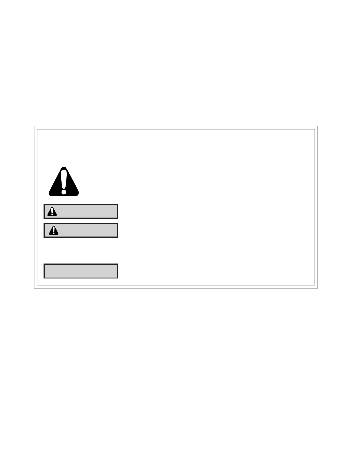
Your safety and the safety of others are very important.
We have provided many important safety messages in this manual and on your appliance. Always read
and obey all safety messages.
This is a Safety Alert symbol.
This symbol alerts you to potential hazards that can kill or hurt you and others.
All safety messages will follow the safety alert symbol with the word “WARNING”
or “CAUTION”. These words mean:
WARNING
CAUTION
All safety messages will tell you what the potential hazard is, tell you how to reduce the chance of injury,
and tell you what will happen if the instructions are not followed.
NOTICE
You can be killed or seriously injured if you do not follow instructions.
You can receive minor or moderate injury if you do not follow instructions.
A message to alert you of potential property damage will have the
word “NOTICE”. Potential property damage can occur if instructions
are not followed.
PERSONAL INJURY OR DEATH HAZARDS
ELECTRICAL HAZARDS:
• Unplug and/or disconnect all electrical power to the unit before performing inspections,
maintenance, or service.
• Make sure to follow proper lockout/tag out procedures.
• Always work in the company of a qualied assistant if possible.
• Capacitors, even when disconnected from the electrical power source, retain an electrical charge
potential capable of causing electric shock or electrocution.
• Handle, discharge, and test capacitors according to safe, established, standards, and approved
procedures.
• Extreme care, proper judgment, and safety procedures must be exercised if it becomes necessary
to test or troubleshoot equipment with the power on to the unit.
2

• Do not spray or pour water on the return air grille, discharge air grille, evaporator coil, control panel,
and sleeve on the room side of the air conditioning unit while cleaning.
• Electrical component malfunction caused by water could result in electric shock or other electrically
unsafe conditions when the power is restored and the unit is turned on, even after the exterior is dry.
• Never operate the A/C unit with wet hands.
• Use air conditioner on a single dedicated circuit within the specied amperage rating.
• Use on a properly grounded outlet only.
• Do not remove ground prong of plug.
• Do not cut or modify the power supply cord.
• Do not use extension cords with the unit.
• Follow all safety precautions and use proper and adequate protective safety aids such as: gloves,
goggles, clothing, adequately insulated tools, and testing equipment etc.
• Failure to follow proper safety procedures and/or these warnings can result in serious injury or death.
REFRIGERATION SYSTEM REPAIR HAZARDS:
• Use approved standard refrigerant recovering procedures and equipment to relieve pressure before
opening system for repair.
• Do not allow liquid refrigerant to contact skin. Direct contact with liquid refrigerant can result in minor
to moderate injury.
• Be extremely careful when using an oxy-acetylene torch. Direct contact with the torch’s ame or hot
surfaces can cause serious burns.
• Make sure to protect personal and surrounding property with re proof materials.
• Have a re extinguisher at hand while using a torch.
• Provide adequate ventilation to vent off toxic fumes, and work with a qualied assistant whenever
possible.
• Always use a pressure regulator when using dry nitrogen to test the sealed refrigeration system for
leaks, ushing etc.
• Make sure to follow all safety precautions and to use proper protective safety aids such as: gloves,
safety glasses, clothing etc.
• Failure to follow proper safety procedures and/or these warnings can result in serious injury or death.
MECHANICAL HAZARDS:
• Extreme care, proper judgment and all safety procedures must be followed when testing,
troubleshooting, handling, or working around unit with moving and/or rotating parts.
• Be careful when, handling and working around exposed edges and corners of the sleeve, chassis,
and other unit components especially the sharp ns of the indoor and outdoor coils.
• Use proper and adequate protective aids such as: gloves, clothing, safety glasses etc.
• Failure to follow proper safety procedures and/or these warnings can result in serious injury or death.
3

PROPERTY DAMAGE HAZARDS
FIRE DAMAGE HAZARDS:
• Read the Installation/Operation Manual for the air conditioning unit prior to operating.
• Use air conditioner on a single dedicated circuit within the specied amperage rating.
• Connect to a properly grounded outlet only.
• Do not remove ground prong of plug.
• Do not cut or modify the power supply cord.
• Do not use extension cords with the unit.
• Be extremely careful when using acetylene torch and protect surrounding property.
• Failure to follow these instructions can result in re and minor to serious property damage.
WATER DAMAGE HAZARDS:
• Improper installation, maintenance or servicing of the air conditioner unit can result in water damage
to personal items or property.
• Insure that the unit has a sufcient pitch to the outside to allow water to drain from the unit.
• Do not drill holes in the bottom of the drain pan or the underside of the unit.
• Failure to follow these instructions can result in damage to the unit and/or minor to serious property
damage.
4
INTRODUCTION
This service manual is designed to be used in conjunction with the installation and operation manuals provided with
each air conditioning system.
This service manual was written to assist the professional RAC (Room Air Conditioner) service technician to quickly
and accurately diagnose and repair malfunctions.
This manual will deal with subjects in a general nature.
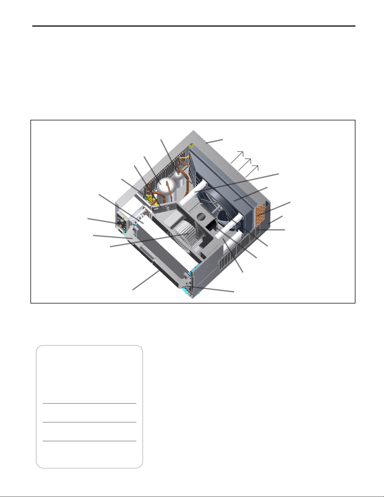
COMPONENTS IDENTIFICATION
Accumulator
Compressor
Outdoor Grille
Discharge Air
Fresh Air Vent
Reversing Valve
Evaporator Coil
Shroud brace
Condense/Fan Shroud
Condenser Coil
Electronic Control
Board
Control Key Pad
Support Bar
Blower Wheel
Air Intake From
Sides and Bottom
Control Key Pad
(User Interface)
IMPORTANT: It will be necessary for you to accurately identify the unit you are servicing, so you can be certain of a
proper diagnosis and repair (See Unit Identication code on page 6).
Chassis Pull
Out Handle
Fan/Blower Motor
Base Pan
Sleeve
Air Intake Vents
Fan Blade
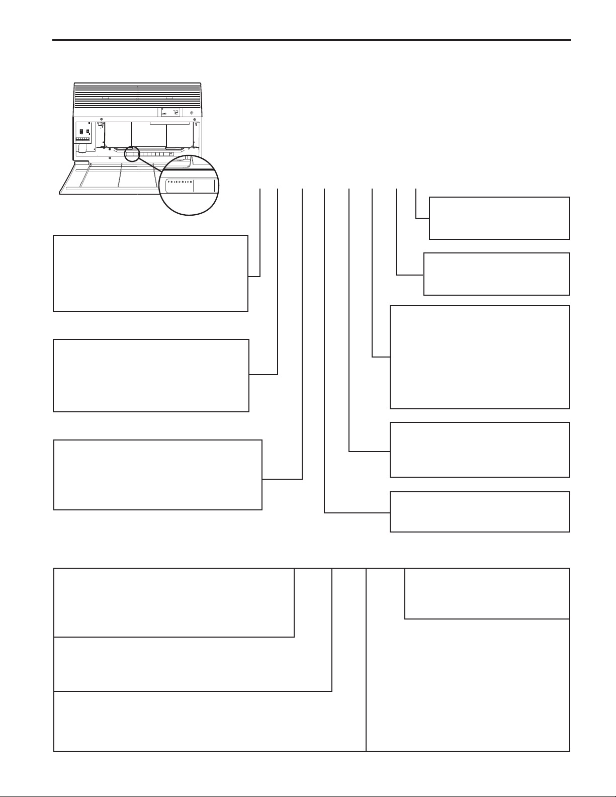
MODEL AND SERIAL NUMBER LOCATION
Register your air conditioner
Model information can be found on the name
plate behind the front cover.
For your future convenience, record the model
information here.
MODEL NUMBER
SERIAL NUMBER
PURCHASE DATE
5
UNIT IDENTIFICATION
COOLING
VOLTS 115
MODEL NUMBER
HEATING
REFRIGERANT
XXXXXXXXX
XXXXXXXXXX
FUSE PROTECTED
U
L
BTH/HR 6500
60 HZ / 1 PH
YS10M10A
BTH/HR 6500
30.1 OZ R410A
600 PSIG HS
XXXXXXXXX
CIRCUITS USE 15A
AIR CONDITIONING CO.
VOLTS MIN 108
SERIAL NUMBER
SAN ANTONIO, TEXAS
LICY00008
ASSEMBLED IN MEXICO
X XX
EER 12.0
EER 10.4
300 PSIG LS
XXXXXXXXXX
TIME DELAY FUSE
XXXXX
AMPS 8.0
AMPS 7.0
XXXXXXXXXX
XXXXXXXXXX
Model Number Code
MODEL NUMBER
YS10M10A
AIR CONDITIONING CO.
SERIAL NUMBER
SAN ANTONIO, TEXAS
LICY00008
ASSEMBLED IN MEXICO
1st Digit – Function
S = Straight Cool, Value Series
Y = Heat Pump
E = Electric Heat
2nd Digit
S = Small Chassis
M = Medium Chassis
L = Large Chassis
3rd and 4th Digit - Approximate
BTU/HR in 1000s (Cooling)
Heating BTU/Hr capacity listed in the
Specication/Performance Data Section
S S 08 M 1 0 B A
9th Digit, Engineering Sufx
Major modication
Subject to change
8th Digit, Marketing Sufx
Indicates modication
Subject to change
7th Digit – Options
0 = Straight Cool &
Heat Pump Models
3 = 3 KW Heat Strip, Nominal
4 = 4 KW Heat Strip, Nominal
5 = 5 KW Heat Strip, Nominal
6th Digit – Voltage
1 = 115 Volts
3 = 230-208 Volts
5th Digit
Alphabetical Modier
RAC Serial Number Identication Guide
Serial Number
Decade Manufactured
L=0 C=3 F=6 J=9
A=1 D=4 G=7
B=2 E=5 H=8
Year Manufactured
A=1 D=4 G=7 K=0
B=2 E=5 H=8
C=3 F=6 J=9
Month Manufactured
A=Jan D=Apr G=Jul K=Oct
B=Feb E=May H=Aug L=Nov
C=Mar F=Jun J=Sept M=Dec
6
A B A R 00001
Production Run Number
Product Line
R = RAC
LISTED
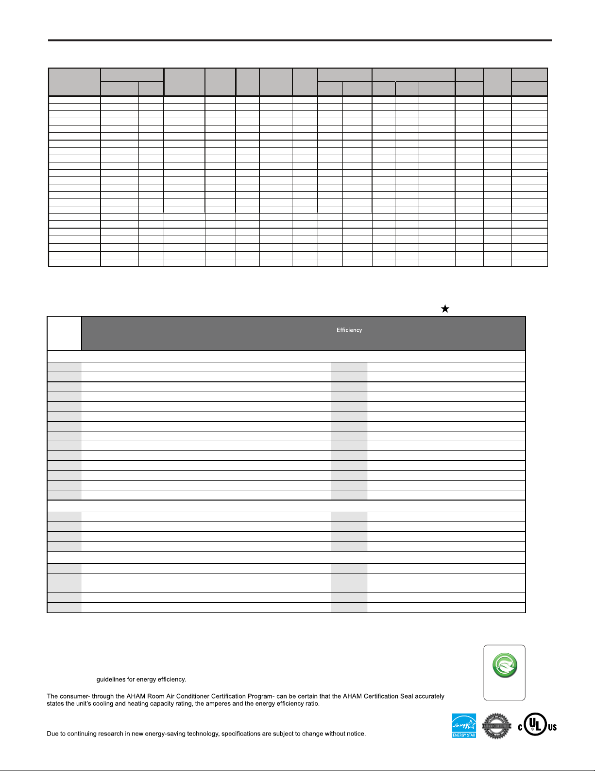
REFRIGERATION SYSTEM PERFORMANCE DATA
COOLING
PERFORMANCE
DATA*
SS08N10-A 54 26 114 153 65 7 19 151 400 6.1 32.0 26.0 115 15
YS10N10-A 59 21 115 155 67 12 14 147 395 7.8 7.6 50.0 26.5 115 15
SS10N10-A 54 26 114 157 68 16 17 137 392 7.7 50.0 27.0 115 15
SS12N10-A 56 24 119 170 60 14 25 135 423 10.0 55.0 30.0 115 15
SS14N10-A 55 25 120 171 62 14 23 141 390 12.0 63.0 31.0 115 15
SS12N30-A 47 33 114 155 58 10 18 134 393 4.8 30.0 31.5 230/208v 15
YS12N30-A 61 19 118 169 69 18 21 137 413 5.2 26.0 32.0 230/208v 20
SS15N30-A 54 26 119 174 59 12 34 127 420 6.4 32.0 33.5 230/208v 15
ES15N33-A 54 26 119 174 59 12 34 127 420 6.4 16.0 32.0 33.5 230/208v 20
SM15N10-A 55 25 118 153 58 10 18 140 410 12.
SM18N30-A 57 23 120 169 61 14 22 136 422 7.4 42.0 39.5 230/208v 15
SM21N30-A 60 20 123 175 65 10 20 130 448 9.4 46.0 40.0 230/208v 15
SM24N30-A 45 35 127 175 50 10 28 119 457 11.2 60.5 43.6 230/208v 20
EM24N34-A 45 35 127 175 50 10 28 119 457 11.2 19.5 60.5 43.5 230/208v 30
YL24N35-A 58 22 119 174 64 22 20 124 417 11.1 12.2 47.0 73.0 230/208v 30
SL22N30-A 54 26 119 159 59 10 20 139 409 9.4 48.0 57.0 230/208v 15
SL24N30-A 54 26 123 163 58 16 19 132 435 11.2 47.0 69.0 230/208v 20
SL28N30-A 54 26 122 173 60 11 26 139 445 12.7 60.0 70.5 230/208v 20
SL36N30-A 52 28 130 190 56 13 33 126 480 18.0 88.0 72.0 230/208v 30
EL36N35-A 52 28 130 190 56 13 33 126 480 18.0 24.0 88.0 72.0 230/208v 30
EVAP. AIR TEMP. DEG.
F
Discharge Air
Temp.
Drop F.
CONDENSER
TEMP DEG. F
Discharge
120 169 61 14 22 136 422 7.4 42.0 39.5 230/208v 30
Temp
Suction
Temp
Super Heat
Sub-
Cooling
OPERATING
PRESSURES
Suction Discharge
ELECTRICAL RATINGS
Amps
Cool
6 63.0 37.0 115 15
Locked Rotor
Amps
Heat
16.0ES12N33-A 47 33 114 155 58 10 18 135 393 4.8 30.0 31.5 230/208v 20
19.5EM18N34-A 57 23
8.5YM18N34-A 48 32 118 169 53 10 21 126 413 8.5 44.0 40.0 230/208v 30
Amps
5.6
R-410A
REF.
Charge in
OZ.
*Rating Conditions: 80 degrees F, room air temp. & 50% relative humidity, with 95 degree F, outside air temp & 40% relative humidity, all
systems use R-410A. Test done at highest unit fan speed.
Voltage
BREAKER
60 Hertz
FUSE
Amps
SPECIFICATIONS
Energy
Volts
MODEL Cooling Btu Heating Btu
®
Kühl
SS08N10 7900 - 115 6.1 677 - - 11.7 $54 - 1.0 265 S 99 121
*
SS10N10 9500 - 115 7.7 848 - - 11.2 $67 - 2.0 260 S 106 136
*
SS12N10 12000 - 115 10.0 1111 - - 10.8 $88 - 3.0 300 S 112 136
*
SS14N10 14000 - 115 12.0 1444 - - 9.7 $115 - 3.5 325 S 116 133
SS12N30 11500/11200 - 230/208 4.8/4.9 1055/1027 - - 10.9/10.9 $84 - 2.8 275 S 112 134
*
SS15N30 14500/14300 - 230/208 6.4/6.8 1480/1459 - - 9.8/9.8 $112 - 3.5 360 S 116 136
SM15N10 14800 - 115 12.0 1358 - - 10.9 $109 - 3.5 360 M 141 154
*
SM18N30 17500/17200 - 230/208 7.4/8.0 1635/1607 - - 10.7/10.7 $131 - 4.6 350 M 140 158
*
SM21N30 20500/20000 - 230/208 9.4/10.3 2181/2128 - - 9.4/9.4 $173 - 6.0 425 M 132 153
*
SM24N30 22300/22000 - 230/208 11.2/11.9 2590/2550 - - 8.6/8.6 $206 - 10.0 390 M 152 167
SL22N30 21000/20500 - 230/208 9.6/10.2 2188/2092 - - 9.6/9.8 $174 - 6.0 625 L 191 212
*
SL24N30 24000/23800 - 230/208 11.2/12.0 2553/2532 - - 9.4/9.4 $207 - 7.0 640 L 192 213
*
SL28N30 27500/27000 - 230/208 13.5/14.4 2926/2872 - - 9.4/9.4 $229 - 8.5 600 L 193 214
*
SL36N30 36000/35700 - 230/208 19.0/20.5 4235/4200 - - 8.5/8.5 $338 - 12.0 725 L 212 227
®
+ Heat Pump
Kühl
YS10N10* 9400 7500 115 7.8 855 7.6 743 11.0 $68 3.0 1.9 285 S 109 131
*
YS12N33 11500/11300 9400/9000 230/208 5.2/5.4 1095/1076 5.6/5.8 1132/1139 10.5/10.5 $87 2.4/2.3 3.0 265 S 115 136
*
YM18N34 18200/17800 17900/17700 230/208 8.5/8.9 1808/1788 8.5/8.7 1833/1761 9.9/9.9 $147 2.5/2.6 5.4 370 M 141 152
*
YL24N35 23500/23000 23500/23000 230/208 11.1/12.0 2500/2447 12.2/14.3 2610/2575 9.4/9.4 $199 2.6/2.6 7.0 600 L 197 212
*
®
Kühl
+ Electric Heat
ES12N33 11500/11200 10700/8900 230/208 4.8/4.9 1055/1027 16.0/14.7 3500/2900 10.9/10.9 $84 - 2.8 275 S 113 128
ES15N33 14500/14300 10700/8900 230/208 6.4/6.8 1480/1459 16.0/14.7 3500/2900 9.8/9.8 $112 - 3.5 360 S 117 133
EM18N34 17500/17200 13000/10600 230/208 7.4/8.0 2590/2550 19.5/17.
EM24N34 22300/22000 13000/10600 230/208 11.2/11.9 2590/2550 19.5/17.0 4200/3500 8.6/8.6 $207 - 10.0 390 M 153 166
EL36N35 36000/35700 17300/14300 230/208 19.0/20.5 4235/4200 24.0/22.4 5500/4650 8.5/8.5 $338 - 12.0 725 L 213 225
* Operates on 115 volt and is not equipped with supplemental heat. Will not provide heat at temperatures below 40°F.
Friedrich room air conditioners are designed to operate in outdoor temperatures from 60°
Kühl+ Heat Pump heating information (shown in red) indicates heat pump per formance. Kühl+ and Chill+ Electric Heat heating information
(shown in red) indicates electric heat strip performance. For Kühl+ Heat Pump electric heating performance
Electric Heat model.
®
As an ENERGY STAR
ENERGY STAR
partner, Friedrich Air Conditioning Co. has determined that the selected ENERGY STAR® models meet the
®
Rated
Cooling
Amps
Cooling
Watts
Heating
Amps
Heating
Watts
0 4200/3500 8.6/8.6 $131 - 4.6 350 M 141 158
F to 115° F.
Ratio
Estimated
Yearly
Operating
EER
Cost COP
refer to corresponding Kühl+
ENERGY STAR
Moisture
Removal -
Pints/HR CFM Sleeve
All models use
environmentally
friendly R-410A
®
models
Net WtShip
R-410A
refrigerant.
Wt.
Estimated yearly operating cost based on a 2007 national average electricity cost of 10.65 cents per kWh.
7
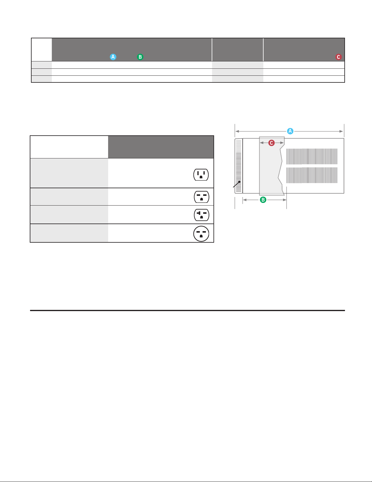
Installation Information / Sleeve Dimensions
Sleeve
Height Width
Depth
with Front
Shell Depth to
Louvers
Minimum
Extension
Into Room*
Minimum
Extension
Outside*
Window Width
Thru-the-wall Installation
Finished Hole
Minimum** Maximum Height Width Max. Depth
S 15
15
/16
" 25
15
/16
" 29"
8
¾"
5
¾”
16
15
/16
” 27
3
/8
" 42 " 16
3
/16”
26
3
/16”
7
3
/8
"
M 17
15
/16
" 25
15
/16
" 29"
8
¾"
5 ¾”
16
15
/16
” 27
3
/8
" 42 " 18
3
/16”
26
3
/16”
7
3
/8
”
L 20
3
/16"
28" 35 ½”
16
½"
5
3
/8
” 18
15
/16
” 29
7
/8
” 42" 20
3
/8
" 28 ¼" 15
1
/8
”
For the best cooling performance and highest energy efficiency
* Minimum ex tensions when mounted in a window.
** Minimum widths achieved using one side curtain assembly as opposed to both in a standard installation.
NOTE: S,M and L sleeves may be installed in window with no side kits if properly installed.
Circuit Rating/ Breaker
Model
SS08N10, SS10N10, SS12N10 and
SS14N10, SM15N10, YS10N10
SS12N30, SS15N30, SM18N30 and
SM21N30, S L22N30
SM24N3 0, SL24N30,SL28N3 0,
ES12N33, ES15N33, YS12N33
SL36N30, EM18N34, EM24N34,
EL36N 35, YM18N34 and YL24N35
Circuit Rating
Breaker or
T-D Fuse
125V - 15A 5 - 15P 6
250V - 15A 6 - 15P 4
250V - 20A 6 - 20 P 4
250V - 30A 6 - 30P 4
Plug
Face
(NEMA#)
Power Cord
Length (f t.)
Wall Outlet
Appearance
Front
(C)
(B)
SIDE VIEW
Keep the filter clean
Make sure that your air conditioner is always in top performing condition
.ylralugerretlifehtgninaelcyb
Provide good air flow
Make sure the airflow to and from the unit is clear. Your air conditioner puts the
conditioned air out at the top of the unit, and takes in unconditioned air at the
bottom. Airflow is critical to good operation. It is just as important on the outside
.dekcolbtonsiroiretxetinuehtdnuorawolfriaehttahtgnidliubehtfo
Unit placement
If your air conditioner can be placed in a window or wall that is shaded by a tree
Insulation
Good insulation will be a big help in maintaining desirable comfort levels.
Doors should have weather stri
pping.
windows.
Proper installation of seal gasket
Make sure the seal gasket has been installed properly to minimize noise
and improve effi ciency. If the seal gasket has not been installed, please
refer to the installation instructions.
rosepardgnisU.yltneiciffeeromneveetarepolliwtinueht,gnidliubre hto naro
blinds on the sunny side of the dwelling will also add to your unit’s efficiency.
8
Be sure to caulk around doors and
LISTED
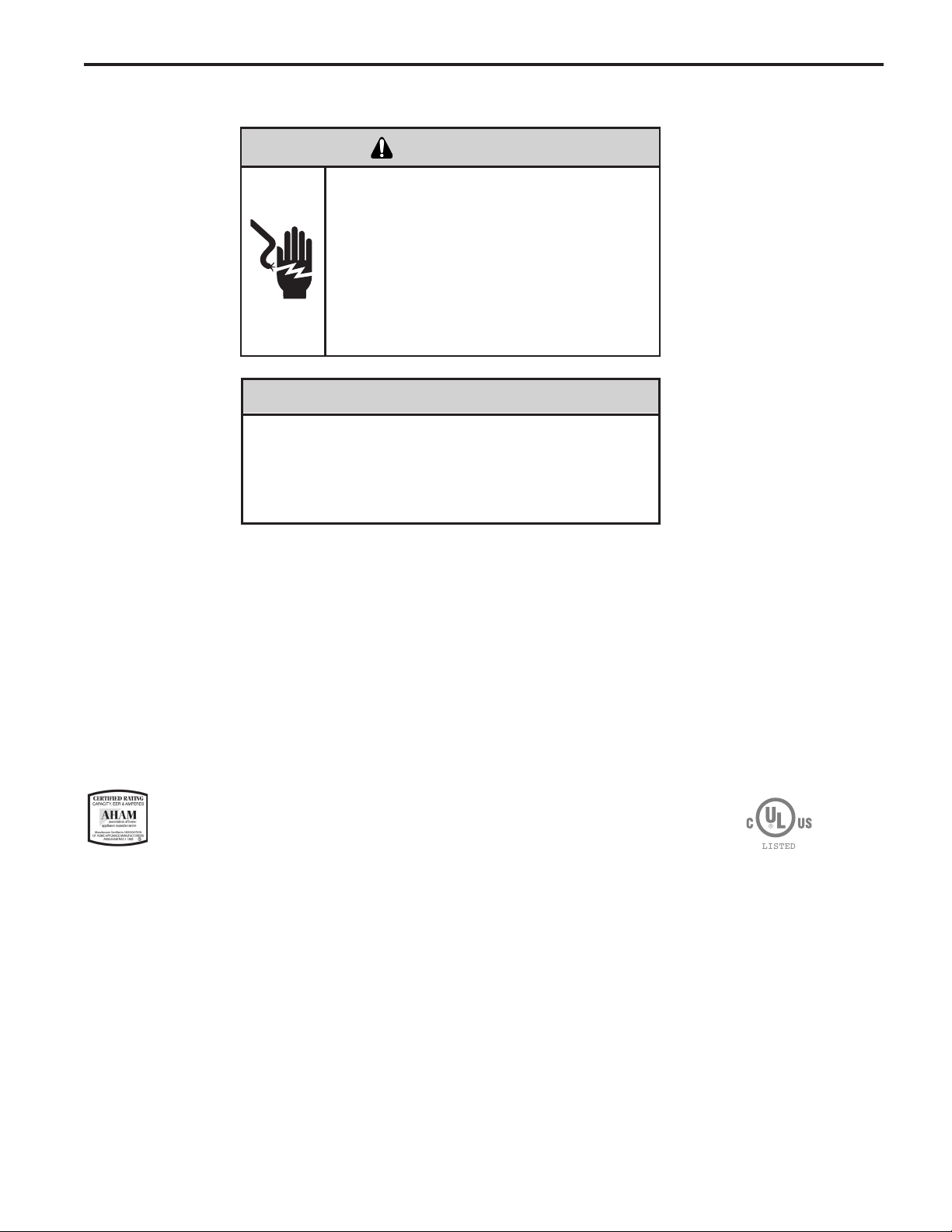
ELECTRICAL DATA
Not following the above WARNING could result in re or
electically unsafe conditions which could cause moderate
or serious property damage.
Read, understand and follow the above warning.
WARNING
ELECTRIC SHOCK HAZARD
Turn off electric power before service or
installation.
All electrical connections and wiring MUST be
installed by a qualied electrician and conform to
the National Electrical Code and all local codes
which have jurisdiction.
Failure to do so can result in personal injury or
death.
NOTICE
FIRE HAZARD
Wire Size Use ONLY wiring size recommended for single outlet branch circuit.
Fuse/Circuit Breaker Use ONLY the correct HACR type and size fuse/circuit breaker. Read electrical ratings on unit’s
rating plate. Proper circuit protection is the responsibiity of the homeowner.
Grounding Unit MUST be grounded from branch circuit through service cord to unit, or through separate
ground wire provided on permanently connected units. Be sure that branch circuit or general
purpose outlet is grounded.
Receptacle The eld supplied outlet must match plug on service cord and be within reach of service cord.
Do NOT alter the service cord or plug. Do NOT use an extension cord. Refer to the table above
for proper receptacle and fuse type.
The consumer - through the AHAM Room Air Conditioner Certication Program - can
be certain that the AHAM Certication Seal accurately states the unit’s cooling and
heating capacity rating, the amperes and the energy efciency ratio.
*HACR: Heating Air Conditioning and Refrigeration
9
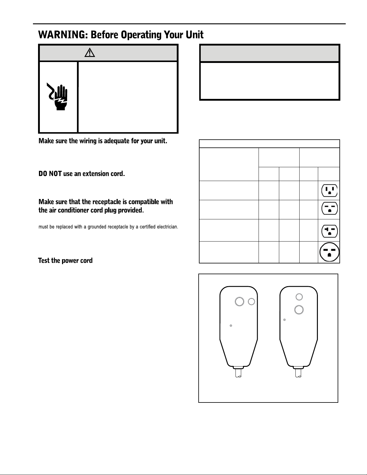
WARNING
NOTICE
Electrical Shock Hazard
Make sure your electrical receptacle has the
same configuration as your air conditioner’s
plug. If different, consult a Licensed Electrician.
Do not use plug adapters.
Do not use an extension cord.
Do not remove ground prong.
Always plug into a grounded 3 prong oulet.
Failure to follow these instructions can result in
death, fire, or electrical shock.
If you have fuses, they should be of the time delay type. Before you install
or relocate this unit, be sure that the amperage rating of the circuit breaker
or time delay fuse does not exceed the amp rating listed in Table 1.
The cord provided will carry the proper amount of electrical power to the
unit; an extension cord may not.
Proper grounding must be maintained at all times. Two prong receptacles
The grounded receptacle should meet all national and local codes and
ordinances. You must use the three prong plug furnished with the air
conditioner. Under no circumstances should you remove the ground
prong from the plug.
Do not use the LCDI device as an ON/OFF switch.
Failure to adhere to this precaution may cause
premature equipment malfunction.
Once plugged in, the unit will operate normally without the need to reset
the LCDI device. If the LCDI device fails to trip when tested or if the power
supply cord is damaged, it must be replaced with a new power supply cord
from the manufacturer. Contact our Technical Assistance Line at (800)
541-6645. To expedite service, please have your model number available.
Table 1.
MODEL
SS08N10, SS10N10,
SS12N10, SS14N10,
SM15N10,
YS10M10
SS12N30, SS15N30,
SM18N30,
SM21N30
SL22N30
SL24N30, SL28N30,
ES12N33, ES15N33,
YS12N33
SL36N30, EM18N34,
EL36N35,
EM24N34, 30 250 6-30R
YM18N34, YL24N35
CIRCUIT RATING
OR TIME DELAY
FUSE
AMP VOLT
15 125 5 -15R
15 250 6-15R
20 250 6-20R
REQUIRED
WALL
RECEPTACLE
NEMA
NO.
All Friedrich room air conditioners are shipped from the factory with a
Leakage Current Detection Interrupter (LCDI) equipped power cord. The
LCDI device on the end of the cord meets the UL and NEC requirements
for cord connected air conditioners.
To test your power supply cord:
1. Plug power supply cord into a grounded 3 prong outlet.
2. Press RESET (See Figure 1).
3. Press TEST, listen for click; the RESET button trips and pops out.
4. Press
and release RESET (Listen for click; RESET button latches
and remains in). The power cord is ready for use.
Note: in case of power failure, unit will resume operation
according to the last input settings.
Figure 1
RESET
TEST
WARNING
TEST BEFORE EACH USE
1. PRESS RESET BUTTON
2. PLUG LCDI INTO POWER
RECEPTACLE
3. PRESS TEST BUTTON,
RESET BUTTON SHOULD
POP UP
4. PRESS TEST BUTTON,
FOR USE
DO NOT USE IF ABOVE TEST
FAILS
WHEN GREEN LIGHT IS ON
IT IS WORKING PROPERLY
15/20A LCDI Device 30A LCDI Device
TEST
RESET
WARNING
TEST BEFORE EACH USE
1. PRESS RESET BUTTON
2. PLUG LCDI INTO POWER
RECEPTACLE
3. PRESS TEST BUTTON,
RESET BUTTON SHOULD
POP UP
4. PRESS TEST BUTTON,
FOR USE
DO NOT USE IF ABOVE TEST
FAILS
WHEN GREEN LIGHT IS ON
IT IS WORKING PROPERLY
FRR001
10
Kuhl Control Options
Kühl Control Options
The
Kühl gives you a variety of options for control, programming, and
scheduling including wireless capabilities
Wireless Programming and Control:
The new FriedrichLink™ Adapter (sold seperately) allows you to conviently
control, program and monitor your air conditioning unit remotely from a
smartphone or computer.
FriedrichLink™ Adapter accessory available through Friedrich authorized
retailers or www.friedrich.com. See FriedrichLink™ Adapter section on
www.friedrich.com for complete details.
Pre-Programmed Scheduling Options:
Your unit’s digital control comes equipped with a 24-hour timer and two preprogrammed 7-day energy management options.
24-Hour Timer
The 24-hour timer allows you to turn the unit off and on at pre-set times by
setting an on and off time on the unit control panel. (See page 11 for details on
timer set-up.)
Pre-programmed Energy Management
Your unit comes from the factory with two (2) Pre-programmed
Management settings are shown in Addendum 1 (Residential & Commercial
Schedule Table).
Energy Management Schedule Options are:
1. Residential Schedule – 40 Hr. Work Week
2. Commercial Schedule – 7-Day Business Week
E
nergy
The “Residential” (40 Hr. Work Week) Schedule has four (4) time periods: 06:00,
08:00, 18:00, and 22:00. This option will cause your Kühl Q unit to raise the room
temperature temporarily to 85°F during the hours wh
en most people are away
at work, lower them again to 78°F prior to the time when most people will return
home, and then raise slightly to 82°F to maintain a comfortable temperature
overnight.
The “Commercial” (7-Day Business Week) Schedule has two (2) time periods:
07:00 and 18:00. This option will cause your air conditioner
to raise temperatures
to 84°F after typical working hours and on weekends when commercial spaces
ar
e ty
pically unoccupied.
(See Control Panel Operation Instructions Section)
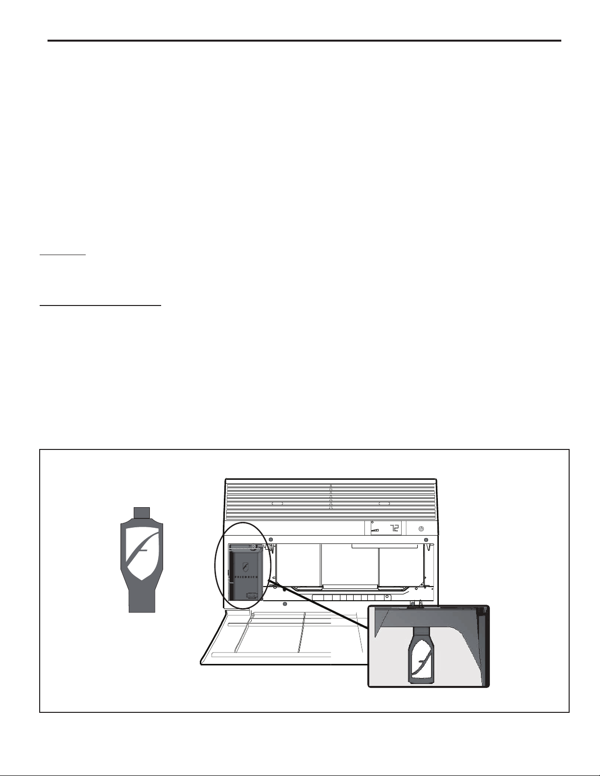
Customizable Programming Options:
Customizable schedules, with up to four temperature adjustments per day, can
either be uploaded to the unit via the air conditioner’s built-in micro USB interface
or conveniently transmitted wirelessly using the new FriedrichLink™ Adapter
accessory, greatly simplifying the programming of one or multiple units.
See Figure 2.
See www.friedrich.com for complete Customizable
Programming instructions.
Smart Grid
The Kuhl Unit is also able to be controlled by a Smart Grid.
Smart Grid is a network that brings electricity from power stations to
consumers using new technologies that allow power companies to adjust
electrical loads of residential users. Check with your local electric company
to learn more about Smart Grid programs in your area.
Figure 2
FriedrichLink™ Adapter
AIR CONDITIONING CO.
SAN ANTONIO, TEXAS
ASSEMBLED IN MEXICO
MODEL NUMBER
HEATING
REFRIGERANT
XXXXXXXXX
XXXXXXXXXX
VOLTS 115
COOLING
YS10M10A
60 HZ / 1 PH
BTH/HR 6500
SERIAL NUMBER
VOLTS MIN 108
EER 12.0
LICY00008
AMPS 8.0
FUSE PROTECTED
U
L
BTH/HR 6500
30.1 OZ R410A
EER 10.4
AMPS 7.0
X XX
600 PSIG HS
XXXXXXXXX
CIRCUITS USE 15A
XXXXX
300 PSIG LS
XXXXXXXXXX
TIME DELAY FUSE
XXXXXXXXXX
XXXXXXXXXX
11
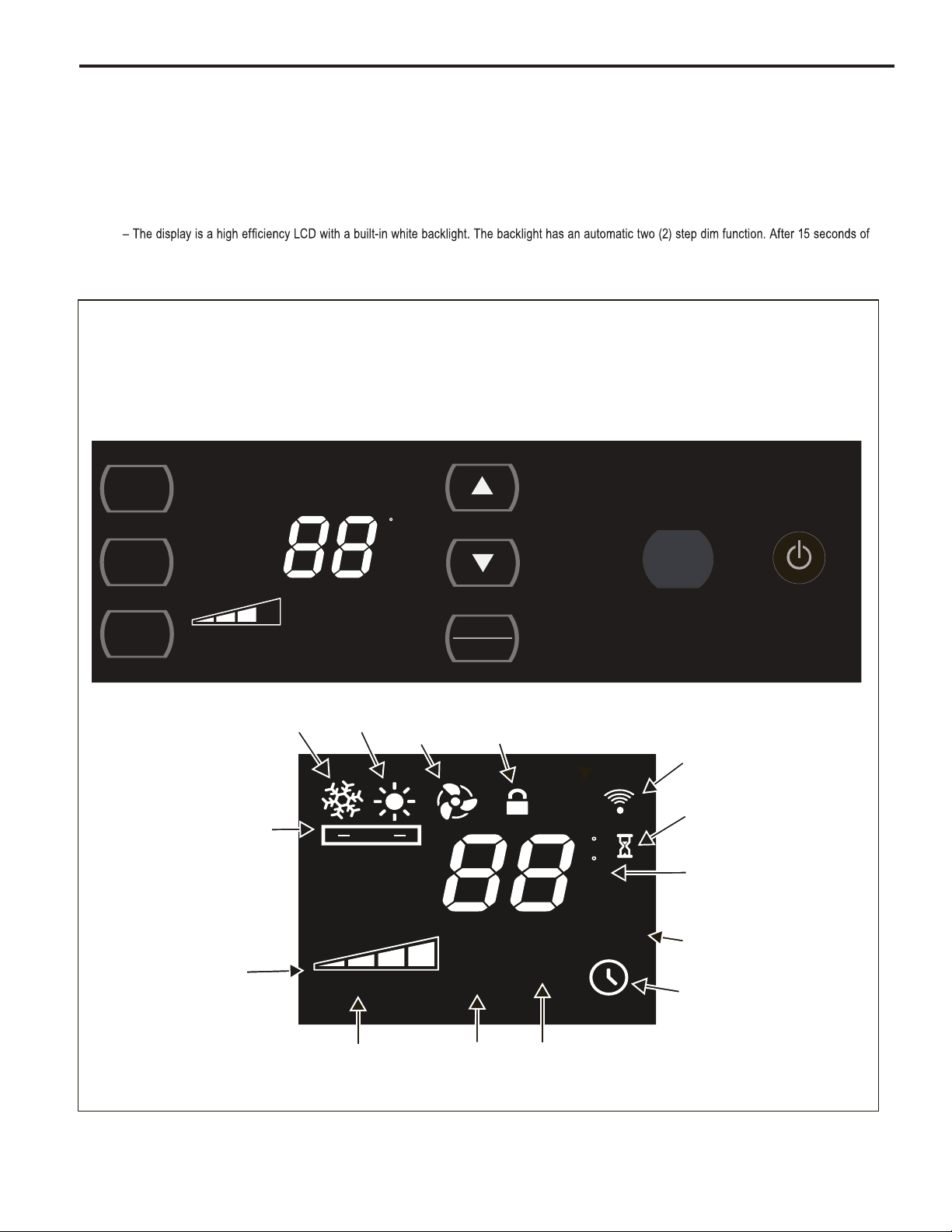
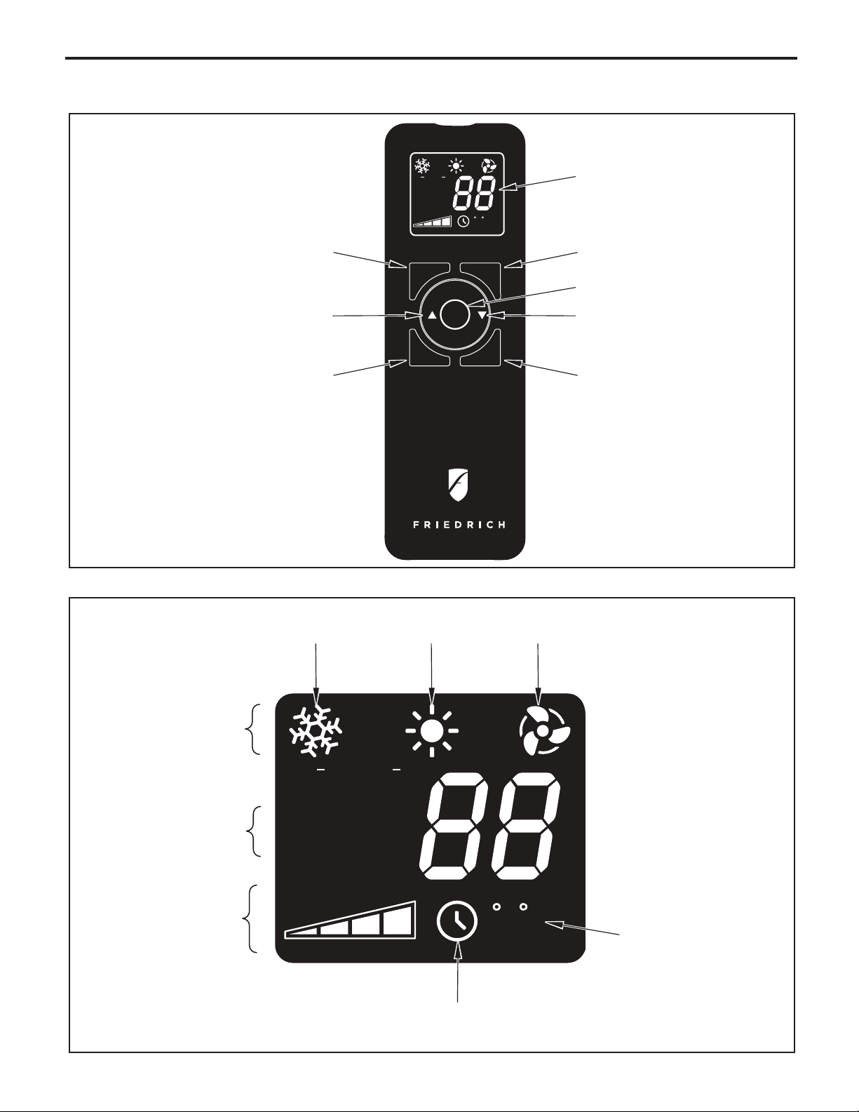
Control Panel and Display Identication
Let’s check out how to control your air conditioner. On the control panel, just above the POWER , is a liquid crystal display (LCD). All of the control panel function
buttons and mode icons can be viewed in Figure 3.
Power On – Press the button to turn on the air conditioner. The power button illuminates to indicate that the power is on. The backlight on the power switch
will automatically dim to 20
% intensity after 15 s
Display
inactivity, the display dims to 20% intensity. After an additional 120 seconds, the display switches off. Touching any button automatically changes the display
to full brightness.
There are three control push buttons on each side of the display.
Figure 3
econds of inactivity. The remote control can also be used to turn power ON / OFF (See Remote Control).
SYSTEM
Cycles between
AUTO, HEAT,
COOL, or FAN
ONLY
(if equipped)
SYSTEM
FAN
MODE
FAN
SPEED
AUTO
Automatically switches
between cool & heat
FAN MODE
Sets fan to either:
- Cycle automatically
- Run continuously
AUTO SPEED
COOL FAN
FAN SPEED
Sets fan speed:
LOW, MED,
HIGH or AUTO
(if equipped)
SET POINT
HEAT
AUTO
AUTO FAN
CONTINUOUS
TEMPERATURE
Increment UP
TEMPERATURE:
Increment DOWN
F
TIMER
SCHEDULE
ONLY
CONTROL
LOCKED
SET POINT
ROOM TEMP
TIMER / SCHEDULE
Turns ON or OFF
F
C
AM
PM
ON OFF
SCHEDULE
:
IR WINDOW
Do not block
ON / OFF
Turns unit on/off
WI-FI
OPERATING
(if equipped)
WAIT
(3 minutes compressor time delay)
2 DIGIT DISPLAY
Shows Setting for:
- Set Point (Temperature)
- Room Temperature
- Clock (AM/PM)
SCHEDULE ON
12
FAN SPEED
Manually selected
fan speed
AUTO SPEED
AUTO SPEED
Automatically selects
best fan cooling or
heating speed
CHECK
FILTER
FILTER
Check / Clean
$MART
TIMER ON
$MART OPERATING
(if equipped)
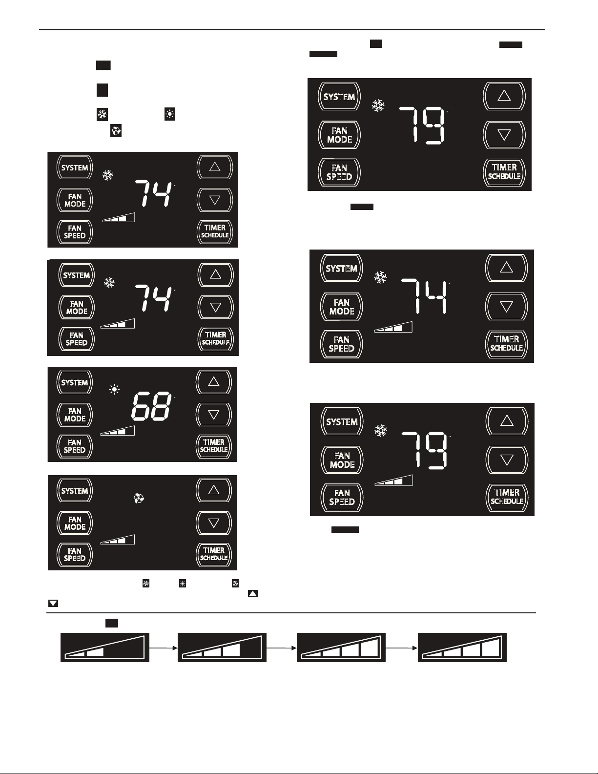
Control Panel Operation Instructions
SYSTEM - The
of operation. To select, press once and let go.
SYSTEM
button allows you to sequentially select the modes
FAN
FAN MODE – The
CONTINUOUS
modes. To select, press once and let go.
MODE
button allows you to select between
AUTO FAN
and
AUTO MODE
COOL MODE
F
AN ONLY MODE
Automatically changes between HEAT and COOL
(HEAT and COOL ONLY Units)
HEAT MODE N
AUTO MODE COOL
- AUTO -
AUTO FAN
SET POINT
COOL ONLY MODE
AUTO FAN
SET POINT
HEAT MODE
AUTO FAN
ot available on some models
F
FRR204
F
FRR103
F
F
AUTO FAN
SET POINT
FRR112
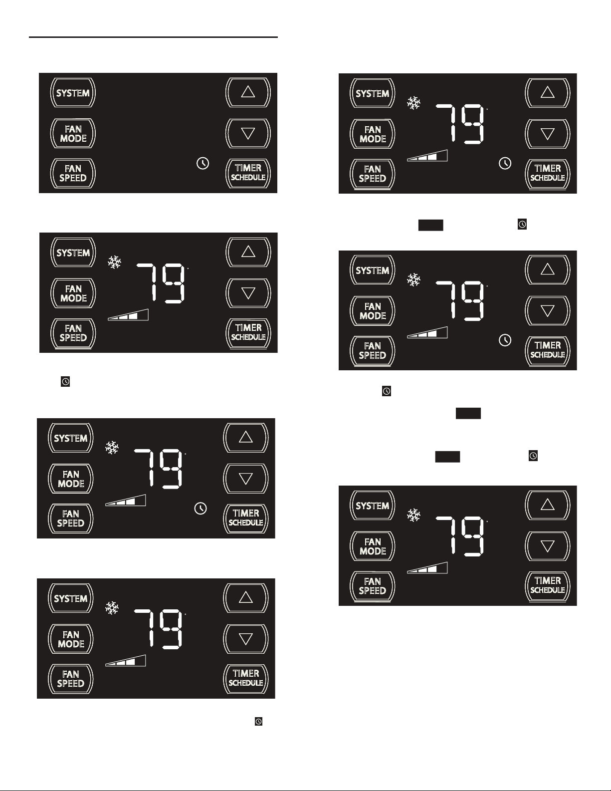
When in the
AUTO FAN
mode, the fan operates only when the system has
a demand to cool or heat the room. Note: the fan is off (no fan speed icon),
indicating no command for cooling or heating.
AUTO FAN (Cooling Demand)
F
AUTO FAN
SET POINT
FRR106
System has a demand for cooling. The fan is operating at a medium speed.
CONTINUOUS
SET POINT
F
CONTINUOUS
SET POINT
FRR113
fan mode, the fan operates all the time. The system
FAN ONLY MODE
FRR104
In the
CONTINUOUS
periodically cools or heats the fan's airfl ow but the fl ow of air does not stop.
When in the SYSTEM COOL or HEAT or FAN ONLY mode, you
FRR105
FAN SPEED - Cooling only units have 4 fan speeds, except models
SL28 and SL36. All Cool+Heat units only have 3 fans speeds.
can also select FAN MODE, FAN SPEED, TIMER SCHEDULE, and
. The SYSTEM MODE does not change.
FAN SPEED - The
FAN
button allows you to toggle between four speeds: LOW, MEDIUM, HIGH, MAX and AUTO speed operation. Press once and let go each time.
SPEED
AUTO
4 Speed
FRR095
During the (SYSTEM mode COOL or HEAT), the fan speed automatically varies depending on the difference between the unit's set point on the control
panel and the actual room temperature. Let me explain. Say for example, you’re working in your garage and you open the big door for several minutes. The
system will sense a wide difference between the set point and the actual room temperature. When this occurs, the system fan speed increases to HIGH for
iod of time. The fan speed decreases, in step, as the temperature difference decreases. When the room temperature matches the system's set point,
a per
fan speed returns to the lowest setting, and if the fan mode is on AUTO FAN, the fan will stop.
13
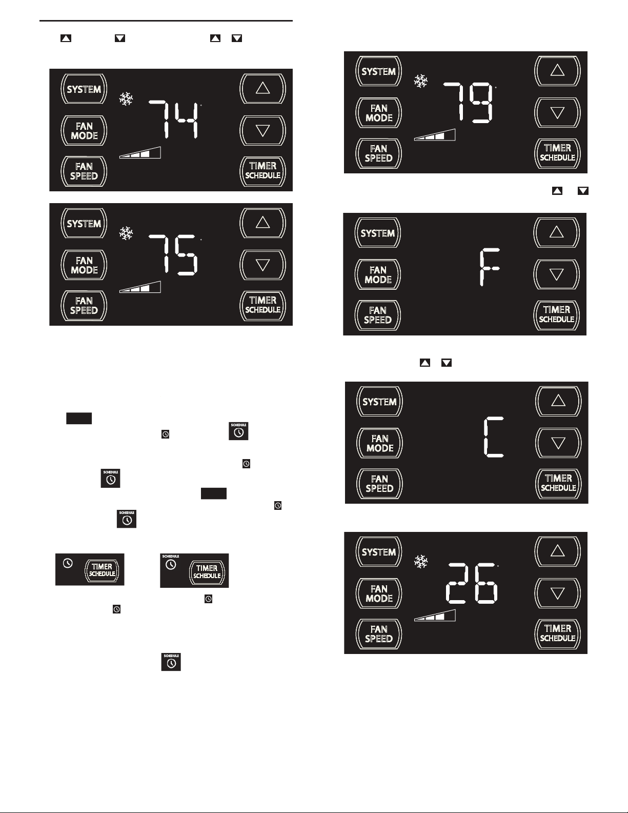
UP and DOWN - arrows - Pressing either or button changes
the system's set point (desired room temperature). These buttons are also
used for setting the Timer and other programming.
F
AUTO FAN
SET POINT
FRR100
F
AUTO FAN
SET POINT
ºF - ºC Select
F
AUTO FAN
SET POINT
FRR132
To switch from degrees Fahrenheit (F) to Celsius (C), press and
buttons simultaneously for three seconds.
FRR101
One press equals 1 degree of change. Holding the button down for more
than 0.6 seconds starts the fast increment/decrement change of the set
point.
TIMER SCHEDULE BUTTON -
TIMER
SCHEDULE
The button has two main uses:
1.Used to preselect a TIMER or SCHEDULE function. (For
pre-selection instructions, please see page 17.)
2. Used to turn on or activate the pre-selected TIMER or
SCHEDULE .
3. To turn on your pre-selction, press the button once and let
TIMER
SCHEDULE
go. The display at bottom right will show the TIMER icon or
SCHEDULE icon .
Example:
TIMER is turned ON SCHEDULE is turned ON
TIMER (FACTORY DEFAULT) - The TIM
ER is the default on new
units. The TIMER function allows you to turn the unit one time ON
and one time OFF daily at the times that you select. For example, you
can command the system to turn ON at 8:15 am and to turn OFF at
1:30 pm everyday. (To set the timer, see page 18.)
SCHEDULE- The SCHEDULE has two options with factory
pre-programmed energy management settings: temperature, system
and time settings (see addendum) (for more information, see page 17).
FRR133
An “F” will flash for 5 seconds and then revert to a normal display. To change
from F to C, press the
or button within 5 seconds.
FRR134
A “C” will fl ash for 5 seconds and then revert to a normal display.
C
AUTO FAN
SET POINT
FRR135
The ºF icon goes away and the ºC icon illuminates on the normal display.
Schedule options are:
1. Residential Schedule - 40 hour work week
2. Commercial Schedule - 5 day business week
(These factory pre-programmed settings can only be changed by using
the WiFi FriedrichLink™ adaptor, or with an upload via the mirco USB
port, with which you can create your own custom program. See page 11.)
14
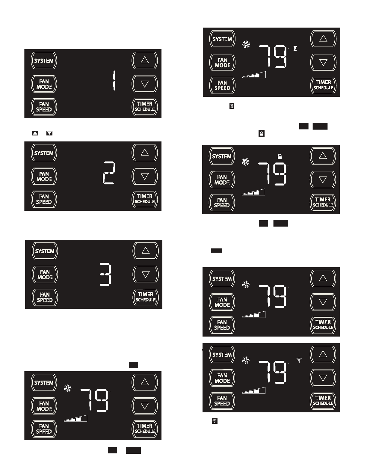
DIM Function
There are three separate display brightness levels, AUTO, 20% and full
(100%). To change the DIM setting, press the Power button for three
seconds.
Wait Icon
F
AUTO FAN
SET POINT
FRR120
The wait icon illuminates when the compressor lockout is active.
FRR192
The 1 indicates a DIM setting of Auto (factory default on new units). Use
the or buttons to change the setting.
FRR193
The 2 indicates a DIM setting of 20%. Press the TIMER SET button within
15 seconds to save the setting. Button inactivity for more than 15 seconds
causes the display to time out and return to the normal operating display.
Control Panel Lock
FAN
To lock the front panel controls, press and hold the
for 3 seconds. The lock icon
illuminates to indicate the locked status.
TIMER
+ buttons
SPEED
SCHEDULE
During lockout, none of the control panel buttons will operate.
F
AUTO FAN
SET POINT
FRR116
To unlock, press and hold the
TIMER
FAN
+ buttons simultaneously for 3
SCHEDULE
SPEED
seconds.
External Control Status
$MART
The icon illuminates to indicate that the system is being controlled
remotely, such as from a smart grid from a power company (for more
information, see page 10).
SMART
F
AUTO FAN
FRR194
The 3 indicates a DIM setting of 100% (full brightness). Press the TIMER
SET (Refer to Figure 8) button within 15 seconds to save the setting.
Button inactivity for more than 15 seconds causes the display to time out
and return to the normal operating display.
Alerts
Check Filter
When the fi lter needs to be cleaned or replaced, the
F
AUTO FAN
SET POINT
CHECK
FILTER
FAN
The alert can be dismissed by pressing the
MODE
15
CHECK
icon displays.
FILTER
TIMER
SCHEDULE
and for 3 seconds.
FRR118
SET POINT
$MART
FRR125
WiFi Connection
F
AUTO FAN
SET POINT
FRR126
The icon illuminates to indicate that the system is receiving a Wi-Fi
connection (for more information, see page 10).
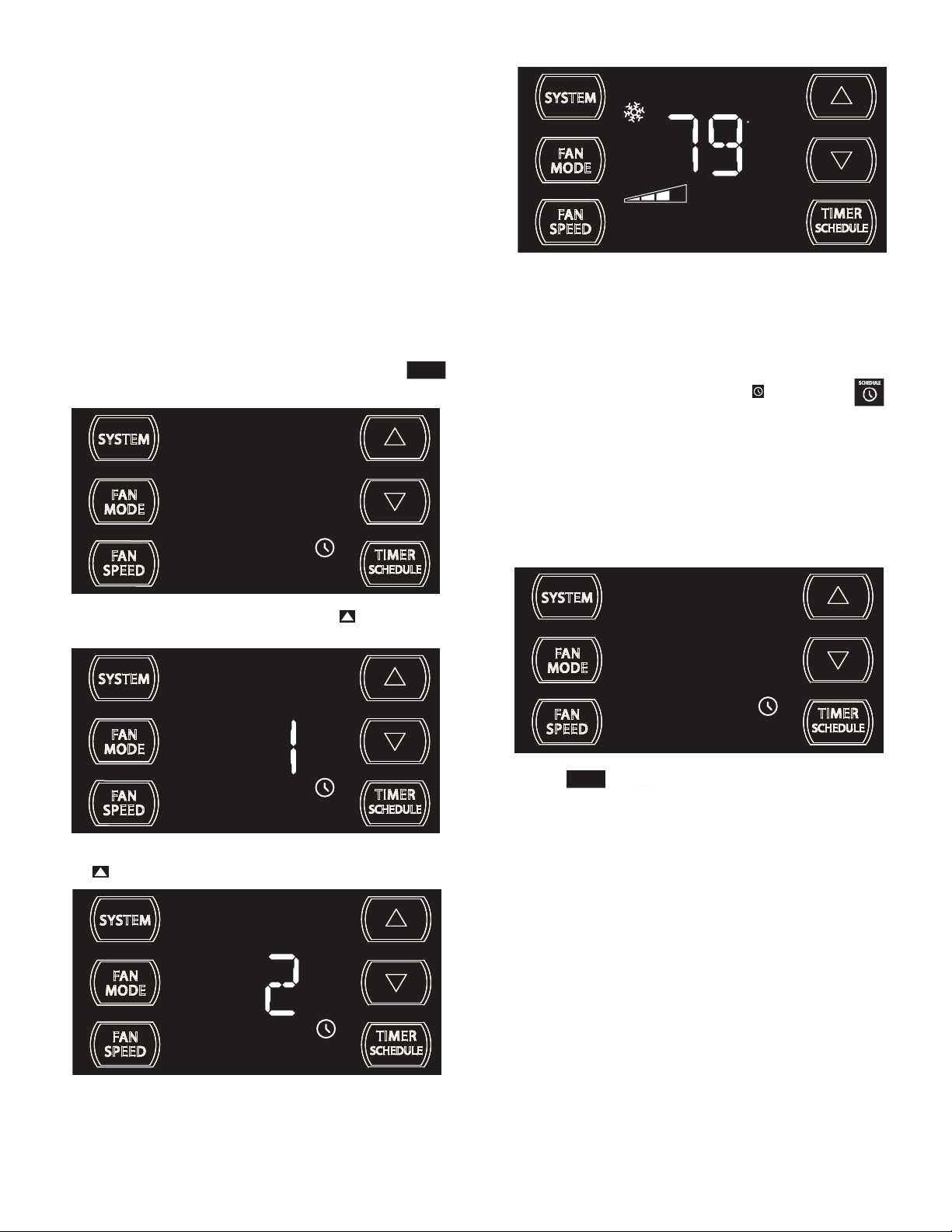
TIMER OR SCHEDULE OPTIONS 1 OR 2 SELECTION
The control system has one Timer and two Schedule functions:
A. Timer (factory default) - Allows you to command the unit to turn
ON and OFF at a time you program. Setting the start, stop and day
can be found latter in this manual on page 18.
B.
Residential Schedule - When selection #1 is selected, the unit
follows a pre-programmed set of operational parameters that
covers 5 days of the week with 4 time windows during each day.
Each time window has it's own set of 8 operating parameters.
Refer to Addendum 1.
C.
Commercial Schedule - When selection #2 is selected, the unit
follows a pre-programmed set of operational parameters that
covers 7 days of the week with 2 time windows during each day.
Each time window has it's own set of 8 operating parameters.
Refer
to Addendum 1.
To change the TIMER/SCHEDULE selection, press and hold the
button for 3 sec, then let go.
TIMER
SCHEDULE
F
AUTO FAN
SET POINT
FRR136
The display reverts to the normal display.
NOTE: The schedule options 1 and 2 have factory pre-programmed
settings which can only be changed by using the WiFi FriedrichLink™
adaptor (an accessory). With it, you can create your own custom
schedule program. See page 10 for more information.
NOTE: Once you have selected the TIMER or SCHEDULE
we must first set the following before turning it on.
1. Set time and day
2. Set start time
3. Set stop time
See timer settings on next page.
FRR139
The display shows the TIMER is selected. Press the button once and
let go.
SCHEDULE
FRR137
The display shows option 1 (Residential Schedule) is selected. Press
the button once and let go.
To Turn On the Timer or Schedule Selected
TIMER
Press the button and let go. The system will operate in the mode
SCHEDULE
option (1, 2 or Timer) you selected. At the above image, TIMER is selected
and turned on.
FRR139
SCHEDULE
The display shows option 2 (Commercial Schedule) is selected.
To save and exit selection, press the TIMER SET button (Figure 4, Page
18).
16
FRR138
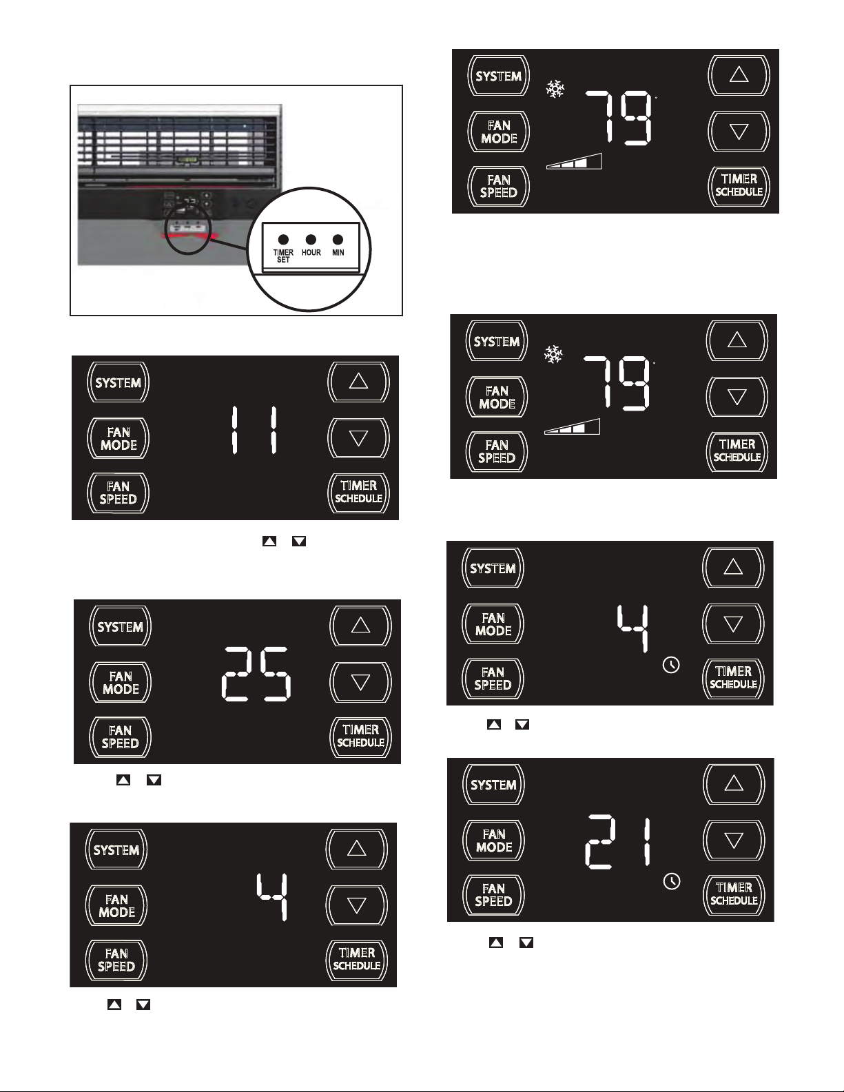
TIMER SETTINGS
1. Set time and day 2. Set start time 3. Set stop time
Figure 4
SET TIME AND DAY - To adjust the unit's time press and hold the HOUR
and the MIN buttons for three seconds (Refer to Figure 4).
AM
F
AUTO FAN
SET POINT
FRR131
Press TIMER SET (Refer to Figure 4) button to exit and save the SET
TIME function. The TIMER SET button must be pressed within 15 second.
Button inactivity for more than 15 seconds causes the display to time out
and return to the normal operating display.
Timer Start Time
F
AUTO FAN
SET POINT
FRR128
The unit's current hour displays. Use the or buttons to adjust the
hour. To change from AM to PM continue to increment (roll) the display.
Press TIMER SET (Refer to Figure 4) button to save the hour and display
the unit’s current minutes.
Use the
or buttons to adjust the minutes. The clock is now set
FRR129
for 11:25 AM. Press TIMER SET (Refer to Figure 4) button to display the
unit's day setting.
FRR140
The display shows a normal system. Press and hold the HOUR button
(Figure 4) for 3 seconds. Note: The Timer start-stop times may be set even
when the system is in the Timer or Schedule mode.
AM
ON
FRR141
Use the or button to adjust the hour. Press the TIMER SET button
(Figure 4) to adjust the minutes.
ON
Use the or buttons to adjust the day (1 to 7). The day setting is up
to the user. If you set the current day = 1. So if today is Tuesday, then
Day 1 = Tuesday, select 1.
17
FRR130
FRR142
Use the or button to adjust the minutes. Press the TIMER SET
button (Figure 4) within 15 seconds to exit and save the setting. The timer
is now set to start at 4:21 AM.
The display will return to normal.
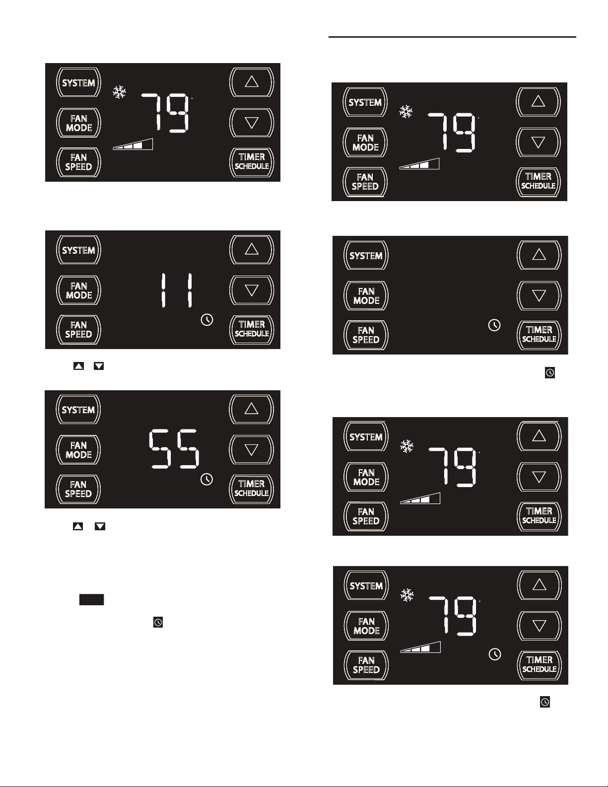
Set theTimer Stop Time
F
AUTO FAN
SET POINT
FRR144
The display shows a normal system. Press and hold the MIN button (Figure
4) for 3 seconds. Note the Timer start - stop times may be set even when
the system is in the Schedule mode.
AM
OFF
Timer ON Scenarios
Scenario 1
F
AUTO FAN
SET POINT
FRR156
The display shows a normal operating system.
FRR145
Use the or button to adjust the hour. Press the TIMER SET button
(Figure 4) to advance to the Minutes section.
OFF
FRR146
Use the or button to adjust the minutes. Press the TIMER SET
button (Figure 4) within 15 seconds to exit and save the setting. The timer
is now set to stop at 11:55 AM. The display returns to normal.
Turning the TIMER ON once the time and day, the start and top times
have been set:
TIMER
Press the button once and let go.
SCHEDULE
NOTE: See the following TIMER ON/OFF scenarios.
FRR157
If the Timer function is turned ON during the Timer’s OFF time, the icon
illuminates. The control system immediately turns the unit OFF.
Scenario 2
F
AUTO FAN
SET POINT
FRR158
The display shows a normal operating system.
F
AUTO FAN
18
SET POINT
FRR159
If the Timer function is turned ON during the Timer’s ON time, the icon
illuminates. The control system immediately turns the unit OFF.
Timer OFF Scenarios
Scenario 1
Timer - Schedule Control Block
F
AUTO FAN
FRR166
The display shows the unit in Timer mode during an in-active (OFF) period.
F
AUTO FAN
SET POINT
FRR167
If the Timer function is turned OFF during an in-active (OFF) period, the
Timer
icon turns off. The display shows a normal system.
Scenario 2
SET POINT
If the unit is operating in the TIMER or SCHEDULE mode, and you press
any bytton except the button, the TIMER icon begins to
TIMER
SCHEDULE
SCHEDULE
FRR148
blink. All button action is blocked.
F
AUTO FAN
SET POINT
SCHEDULE
FRR149
The TIMER icon stops blinking after 3 seconds. You must turn the
active TIMER or SCHEDULE mode OFF before making changes. Once
the changes are made, press the button to re-activate TIMER
TIMER
SCHEDULE
or SCHEDULE mode.
F
AUTO FAN
SET POINT
FRR168
The display shows the unit in Timer mode during an active (ON) period.
F
AUTO FAN
SET POINT
FRR169
If the Timer function is turned OFF during the ON time. The Timer icon
turns off. The control stays in the current state.
The display shows a normal system.
19
If the unit is operating in the TIMER or SCHEDULE mode, and then you
press any button except the button, the TIMER icon begins
TIMER
SCHEDULE
to blink.
F
AUTO FAN
SET POINT
FRR150
All button action is blocked.
Remote Control Operation
Remote Control - Refer to Figures 12 and 13 during operation description.
Getting Started - Install two (2) AAA batteries in the battery compartment
located on the back of the unit.
Operation - The remote control should be within 25 feet of the air
conditioner for operation. (Refer to Figure 11 for effectiveness). Press the
power button to turn the remote on. The remote will automatically power
off aft
er 15 seconds if the buttons are not being pressed. The remote must
be on to cont
POWER Button - Turns remote and unit on and off.
SYSTEM Button - Allows the user to sequentially select the
following: AUTO - AUTO -, COOL
operations. When the button is pressed, the display indicates which mode
has been selected via a display message.Note that when the heating
function is not available, the system will
FAN MODE Button - Selects between automatic (
operation. In the
NOTE:
rol the unit.
HEAT
,
automatically skip the HEAT mode.
AUTO FAN
mode, the fan only turns on and off when the
compressor operates or the heat function is enabled.
AUTO FAN
is not available in the FAN ONLY Mode, the display
indicates
CONTINUOUS
. In the
CONTINUOUS
determined by your selection on the
, and FAN ONLY
AUTO FAN
) or
mode, fan speed is
FAN
button.
SPEED
CONTINUOUS
FAN SPEED Button - Used to sequentially select new fan speed, plus
AUTO operation. When the
FAN
button is pressed, the fan speed icon
SPEED
(triangle) changes to indicate the new speed level. Fan speed automatically
varies depending on the set temperature on the control panel and the actual
room temperature. For example if there is a big difference between your
set temperature and the actual room temperature, the system fan speed
increases to HIGH. It remains at this speed until the room temperature
matches the set temperatur
TIMER/SCHEDULE Button - The button turns the schedule
e.
TIMER
SCHEDULE
function on and off. Press the Schedule button once to turn on the
Schedule (Residential, Commercial, or Timer) that has already been
selected on your unit. Pressing the button a second time turns
TIMER
SCHEDULE
the schedule function off.
UP and DOWN Arrows - Pressing either the
(UP) or (DOWN)
button changes the desired room temperature. The factory preset lower
and upper limits are 60°F (16°C) and 99°F (37°C). These buttons are also
used to navigate between function options when using the User Menu or
Maintenance Mode.
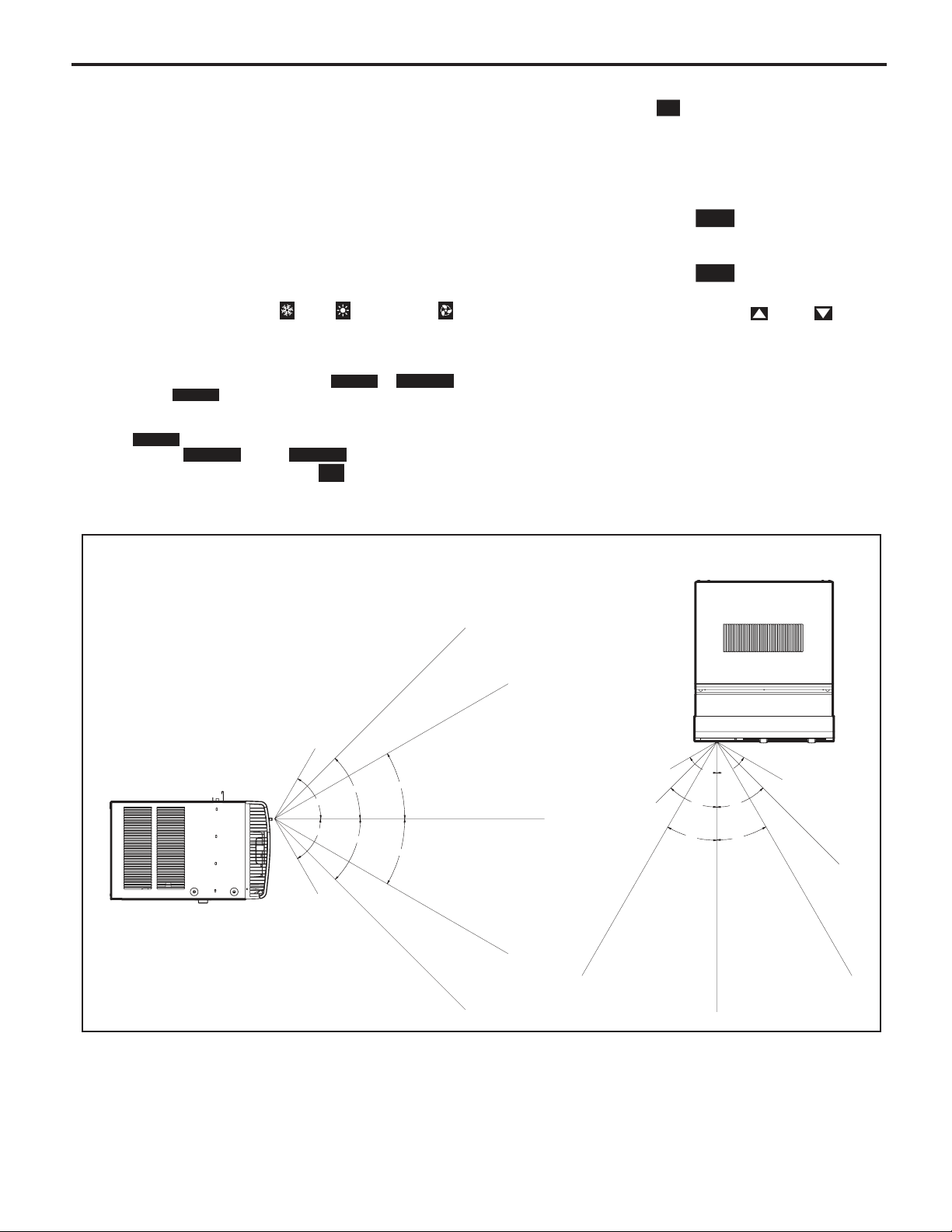
Remote Effectiveness
Hand Held Remote - Has an operating range of up to 25 ft. The infrared
remote control signal must have a clear path to transmit the command to
the air conditioning unit. The remote signal has some ability to "bounce"
off of walls and furniture similar to a television remote control. The diagram
below shows the typical operating range of the control in
with 8 ft high ceilings.
a standard room
Figure 11
SIDE VIEW
TOP VIEW
25ft
25ft
7.5ft
30°
45°
60°
60°
45°
30°
8ft
25ft
25ft
25ft
4ft
8ft
60°
60°
45°
45°
30°
30°
6ft
16ft
25ft
25ft
25ft
Changing Temperature from F˚ (Fahrenheit) To C˚ (Celsius) or Reverse
Be within 25' of unit with the remote control. Press the SYSTEM and FAN MODE buttons at the same time and hold for
3 seconds. The display will show the temperature in Celcius. Do the same to reverse temperature to F
(The remote control operation overrides manual settings on unit)
20
˚ (Fahrenheit).
FRR080
Remote Control Operation (Continued)
Figure 12
SYSTEM
TEMPERATURE
UP
FAN SPEED
AUTO
AUTO FAN
CONTINUOUS
AUTO
SYSTEM
FAN SPEED
POWER
F
C
FAN MODE
SCHEDULE
DISPLAY
FAN MODE
POWER
TEMPERATURE
DOWN
SCHEDULE
FRR081
Figure 13
SYSTEM
MODE
FAN
MODE
FAN
SPEED
COOL
ICON
AUTO
AUTO FAN
CONTINUOUS
AUTO
HEAT
ICON
SCHEDULE
ICON
FAN ONLY
ICON
F
C
°F / °C
ICONs
FRR082
21
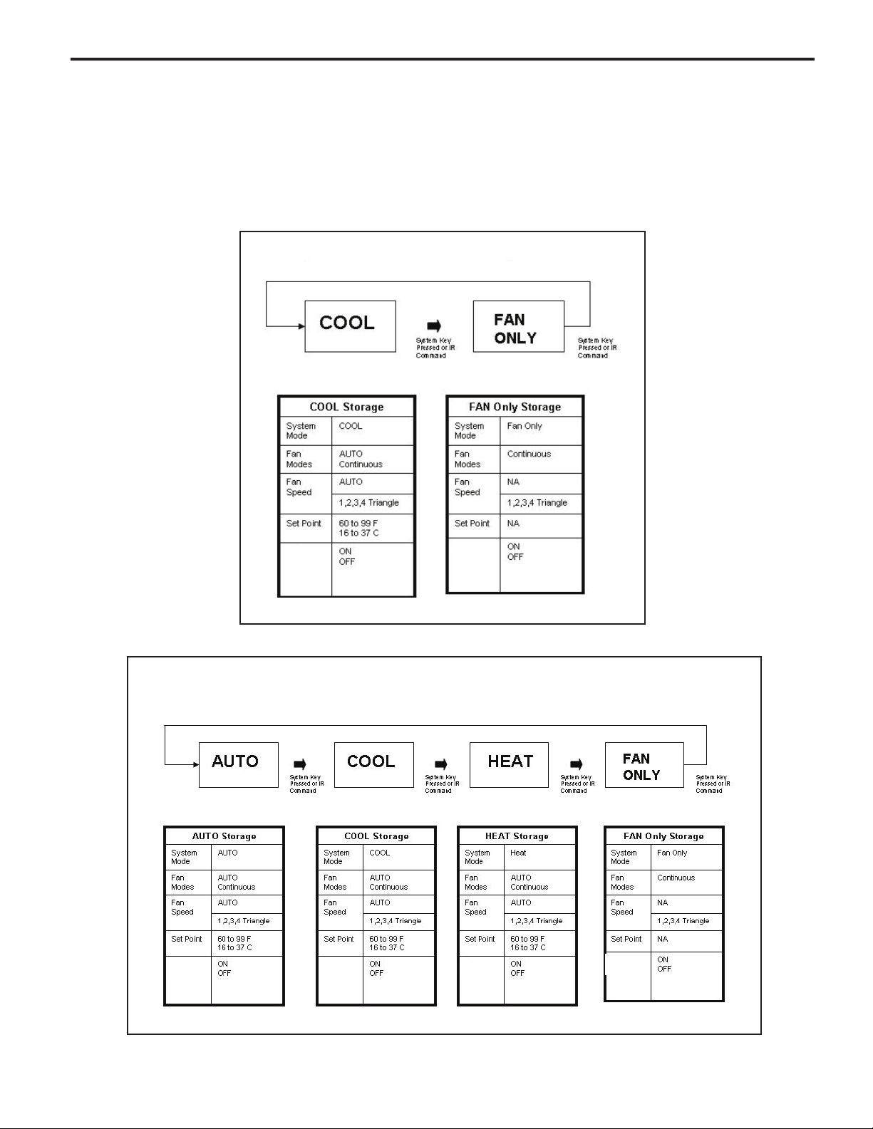
UNIT OPERATION
Front Panel
System Mode Sequence (TIMER/SCHEDULE = OFF)
There are two system modes of operation. One for a cool only unit (see figure 1) and one for a heat-cool unit (see figure 2).
System parameters for each system mode are saved when exiting a system mode, and retrieved when entering a new
system mode.
Figure 1
System Mode: Cool Only Units
Timer/
Schedule
Figure 2
System Mode: Heat - Cool Units
Timer/
Schedule
Timer/
Schedule
Timer/
Schedule
Timer/
Schedule
Timer/
Schedule
22
ELECTRONIC CONTROL SEQUENCE OF OPERATION
Compressor and Reversing Valve Control
Active Mode Compressor
Cooling De-Energized
Heat - Heat Pump
Heat - Electric
Fan Only
* The Reversing valve stays in the last state until a call for heat or cooling (see gure below)
On
On
Off
Off
Reversing Valve State
Energized
Compressor Operation:
The reversing valve only changes when required
to provide cooling or heat pump. The RV valve
stays in it's last state until required to change.
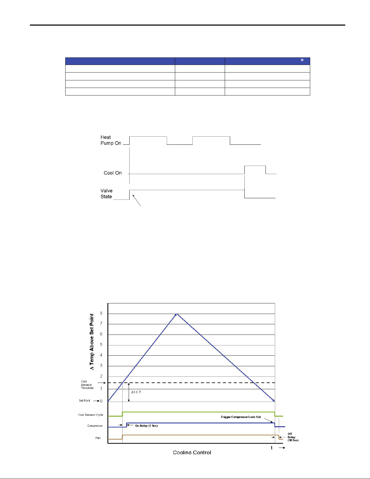
Cooling Mode
Once the ambient temperature rises past the cool demand threshold (Cool Set Point + 1.5 ˚F) (see gure below), and
the compressor is not locked out, the cooling cycle begins. As shown in the gure below, the fan is started 5 seconds
prior to the compressor. Once the ambient temperature has been lowered to the cool set point (Cool Set Point minus
.25 ˚F), the cooling cycle starts to terminate by shutting off the compressor. After a 30 seconds delay, the fan is shut
off. (See gure below for graphic details)
23
Heating Mode Control Operation
There are two heating methods: Heat Pump and Electric Resistance Heat.
There are 3 types of units that provide heating: Heat Pump Only (Model YS10M10)
Heat Pump with Electric Heat and Cool with Electric Heat.
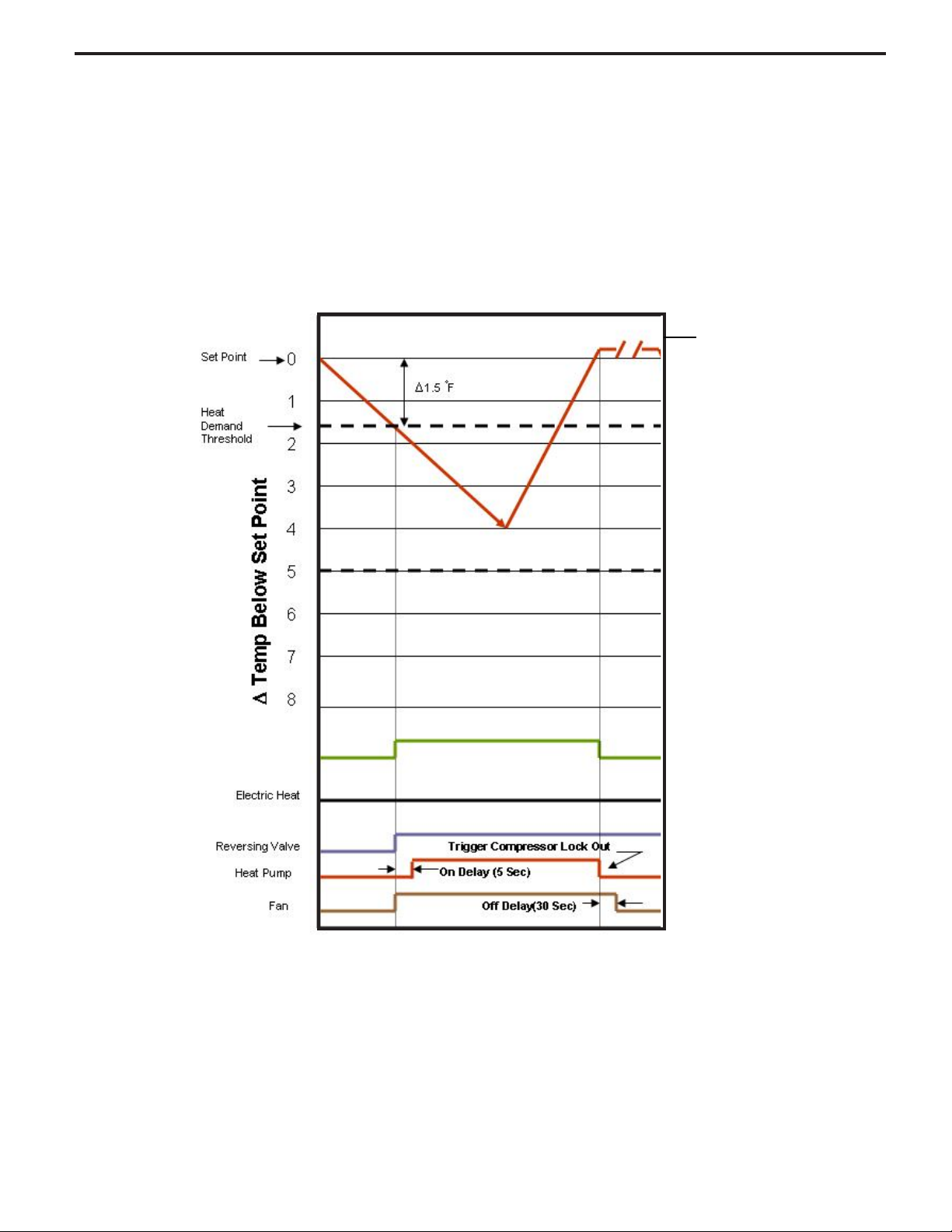
Heat Control Operation Heat Pump Only Unit (YS10M10 has no electric heat back-up)
Once the ambient temperature falls below the Heating Demand Threshold
(1.5 ˚F Below the Heat Set Point Temperature), the heating cycle begins. The fan is turned on 5 seconds before.
Once the ambient temperature has been raised to the Heat Satised Point (Set point + .25 ˚F), the compressor is
turned off. The fan is turned off 15 seconds later. The gure below illustrates the basic heat pump operation.
Satised Point
Heat Control (Heat Pump Only)
YS10M10 Heat Pump Defrost Cycle Operation
The defrost in this unit is an active reverse cycle. The defrost control runs in the background and determines when a
defrost cycle is required. Once initiated, the defrost cycle runs to completion.
The defrost cycle can only be initiated when the heat pump is in operation. The compressor will not be turned off to
avoid activating the compressor's time delay. The reversing valve will be switched to the cool mode position. The
indoor fan/blower will be turned off. Once the defrost cycle is nished, the system should re-enter a heating demand
cycle if required.
When the heat pump run time is 60 minutes or greater with an outdoor coil temperature of 26F degrees or lower, the
control will run an active defrost for up to 6 minutes. When the temperature at the outdoor coil reaches 54F degrees,
the heat pump heat will resume.
24
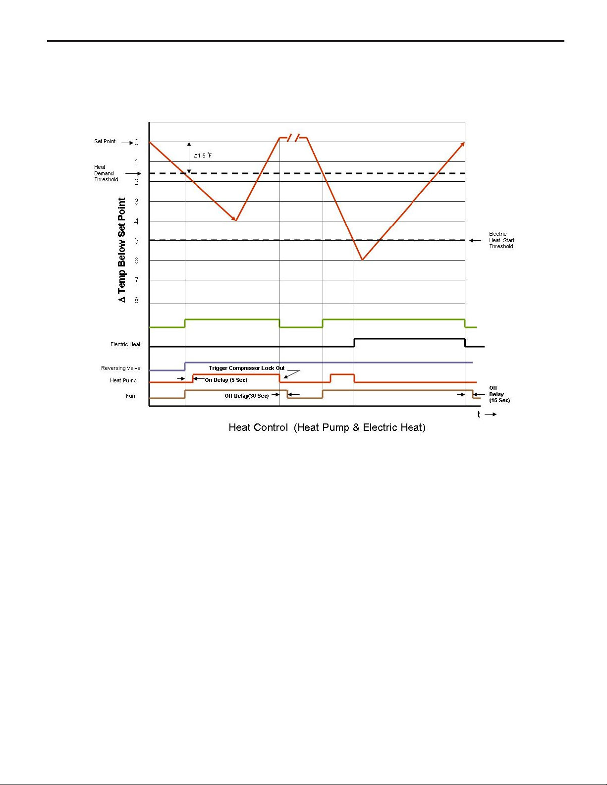
Heat Pump With Electric Heat Operation
This heating is more complex due to the possibility of two heating methods. If the ambient indoor temperature is below the heat demand threshold (1.5˚F below the heat set point temperature), and the compressor is not locked out,
turn on compressor. If the ambient indoor temperature is 0.25˚F above the heat set point turn off the compressor.
If the compressor is locked out & electric heat is available:
1. Turn on the electric heat until the compressor is not locked out.
2. After lockout, turn off the electric heat, wait 5 seconds, then turn on the compressor.
If Electric Heat is Available
After the Heat button is initially pressed, the unit will run the electric heater rst until the initial set point is satised (Hot
Start Feature). After the initial start, the unit will switch to Heat Pump heat and decide between Heat Pump heat and
Electric heat based on the following two monitored conditions:
Condition 1
If the outdoor coil temperature sensor drops to 30 ˚F or less for 2 consecutive minutes, the unit will switch to electric heat
if available. Thereafter, the unit will switch back to Heat Pump heat if the outdoor coil temperature sensor rises to 45 ˚F or
greater.
If Electric Heat is not available (out of order) and the outdoor coil temperature sensor drops to 30 ˚F or less for 2
consecutive minutes, then the compressor and fan will turn off. Thereafter, the unit will switch back to Heat Pump heat if
the outdoor coil temperature rises to 45 ˚F or greater.
25

Heat Pump With Electric Heat Operation (Continued)
Condition 2
If the Δ (delta) (set point temperature minus the ambient indoor temperature) is greater than 5 ˚F, then the unit will switch
to electric heat, if available. The unit will continue to operate with electric heat until the heat demand is satised. Note that
the electric heat switches on after the Δ temp passes 5°F and the heat pump switches off. Also note that the electric heat
will run until the heat demand is satised. When another heat demand cycle is initiated, the heat pump will run unless the Δ
temp is greater than the electric heat threshold.
Automatic Emergency Heat
If the sealed system fails with a bad reversing valve or anything that causes the indoor coil to get colder than the indoor
ambient temperature:
1) If the indoor coil thermistor senses a 5 degree temperature drop as compared to the ambient temperature thermistor
and this lasts up to 5 minutes, the control board will switch the unit to electric heat and continue heating with it.
2) At this point, error code 15 is generated; heat pump failure. Indoor coil temperature lower than indoor ambient
temperature for 5 or more degrees for 5 consecutive minutes.
Note: It is Ok to continue to use the unit with the electric heater until the heat pump is repaired.
Electric Heat Operation in Cool with Electric Heat Units
When in the Heat mode, with and without Fan Mode Auto (Fan cycling):
If the indoor ambient temperature is below the Heat Demand Threshold (Heat Set Point minus 1.5 ˚F), turn on electric heat.
If Ambient is 0.3 ˚F above the Heat Set Point turn off the electric heat.
System Mode Auto
This mode provides automatic change over between cool and heat. The auto mode runs based on the room ambient
temperature vs. the Demand Thresholds. It is only available in Heat-Cool Unit.
Notes:
There is a buffer zone between the cool and heat set points where no heating or cooling is allowed to occur. It is critical
that the Cool Demand Threshold be greater than the Heat Demand Threshold by a minimum of 3° while in the Auto
System Mode. For example, if a user enters a value for the Auto Cooling Set Point that violates the minimum Δ 3° rule, the
Auto Heating Set Point will adjust accordingly.
Automatic Change Over Delay (Cool with Heat Units)
The change over delay ensures that any system heating or cooling over shoot does not trigger an opposite demand cycle.
The change over delay = 15 min. This timer blocks the opposite demand cycle from running until the timer expires. As an
example, if the last demand was a cool cycle, and another cool cycle is requested, the timer will not block the request.
However, if the last demand cycle was a cool cycle, and heat cycle is requested, the timer will block the request until the
change over delay is expired.
26

Compressor Lock Out Time
The lockout feature ensures that the compressor is de-energized for a period of time. The timer varies randomly
from 180 to 240 seconds
The compressor lockout is initiated every time the compressor is “off” due to:
(1) Satisfying the temperature set point
(2) Changing mode to fan only or heat
(3) Turning the unit off
(4) Control is rst plugged in or power is restored after failure
(5) Line power is restored from a brown out condition
Wait ICON (Hour Glass )
The wait icon will be turned on when the compressor is locked out and during demand for cooling or heat pump
compressor operation. The Wait ICON will be turned off when the condition clears.
Cooling Fan Delay
Fan cycle/Auto mode only
When unit cycles cooling ON – starts the fan 5 seconds EARLY. When unit cycles cooling OFF – DELAYS the fan
off for 30 seconds
Note: this fan delay is disabled during Test Mode
Heating Fan Delay
This is only for fan Mode Auto (Fan cycles with cool/heat operation) and not for continuous fan mode. When unit
cycles Heating ON – starts the fan 5 seconds EARLY. When unit cycles Heating OFF – DELAYS the fan off for 15
seconds
Note: the fan delay is disabled during Test Mode
Fan Speed Change Delay
Relay activation is delayed by a minimum number of seconds. The default for this value is 2 seconds and is used to
eliminate relay chatter.
Fan Only System Mode
The fan is turned on and runs at the specied manually set speed.
Only the Fan is turned on. Cool or Heat operation are off.
(This is different than FAN MODE CONTINUOUS where the fan is on with the cool or heat operation).
Fan Only Rules
1. If the SYSTEM FAN ONLY MODE is selected, the Auto fan mode is disabled, and the fan mode is forced to
continuous. In addition, the auto fan speed is disabled. If the user presses the fan speed key, the menu will skip over
the auto selection. The set point temperature display is off.
2. Any fan speed may be manually selected during Fan Only Mode.
27
Fan Operation (Front Panel Mode)
Mode
Heat – Cool – Auto – Fan Only
Models starting with SS, SM have 4 speeds. Models with SL, and all Kuhl+ have 3 speeds
Speed Selection
1 2 3 4 AUTO
AUTO Operation, but never
turns Off. Uses cool set point
or heat set point vs. ambient
temperature. When there is
no demand, operate at the
lowest available speed.
AUTO operation turns On or
Off with heat or cool demand
Uses cool set point or heat
set point vs. ambient
temperature
Fan
Continuous
AUTO
Fan Only
"On" " On" "On" " On"
Turns
On or
Off with
heat or
cool
demand
"On" " On" "On" " On" Disabled
Turns
On or
Off with
heat or
cool
demand
Turns
On or
Off with
heat or
cool
demand
Turns
On or
Off with
heat or
cool
demand
Tabl e
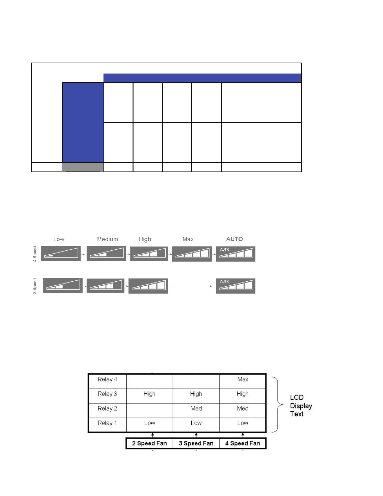
Fan ICON Detail
The system may have a 3 or 4 speed fan. The Fan Speed ICON will Display as per the table below.
Note that in the AUTO mode, the speed of the fan will be shown by illuminating the number of bars in the speed triangle.
Fan Relay Operation
Using the
Front Panel
28
 Loading...