


2002 HAZARDGARD®
ROOM AIR CONDITIONER
Models
SH14J30B-A
SH20J30B-A
Service & Parts
Manual
AMERICA’S BEST AIR CONDITIONER
HG2002 (02/02)

TABLE OF CONTENTS |
|
|
PAGE |
Specifications .................................................................................................................... |
3 |
Performance Data............................................................................................................. |
3 |
Component Operation & Testing ....................................................................................... |
4 |
Compressors .................................................................................................................... |
4 |
Thermal Overload ............................................................................................................. |
4 |
Checking Compressor Efficiency ...................................................................................... |
5 |
Fan Motor ......................................................................................................................... |
5 |
System Control Switch ...................................................................................................... |
5 |
Run Capacitor ................................................................................................................... |
6 |
Thermostat ........................................................................................................................ |
6 |
Low Ambient By-Pass Valve .............................................................................................. |
8 |
Sealed Refrigeration System Repairs ............................................................................... |
8 |
Hermetic Component Replacement .................................................................................. |
9 |
Special Procedure in the case of Compressor Motor Burn-Out ........................................ |
9 |
Rotary Compressor Special Troubleshooting & Service ................................................... |
10 |
Refrigerant Charge ........................................................................................................... |
10 |
TROUBLESHOOTING |
|
Troubleshooting SH14J30B-A ........................................................................................... |
11 |
Troubleshooting SH20J30B-A ........................................................................................... |
16 |
WIRING DIAGRAM |
|
SH14J30B-A / SH20J30B-A ............................................................................................. |
14 |
PARTS LIST |
|
SH14J30B-A / SH20J30B-A Model Chassis Parts List ...................................................... |
18 |
SH20J30B-A / SH20J30B-A Model Cabinet Parts List ...................................................... |
19 |
2
SPECIFICATIONS |
|
SH14J30B-A |
|
SH20J30B-A |
|
|
|
|
|
BTUH |
|
14000/14000 |
|
19000/18800 |
E.E.R. - Btu/watt |
|
8.0/8.0 |
|
8.5/8.5 |
Volts |
|
230/208 |
|
230/208 |
Hertz/Phase |
|
60/1 |
|
60/1 |
Amperes |
|
7.8/8.5 |
|
9.9/10.8 |
Total Watts |
|
1750/1750 |
|
2235/2210 |
Fuse/Breaker Size |
|
15 |
|
20 |
Fan RPM |
|
1095 |
|
1095 |
Evaporator Air CFM |
|
375 |
|
425 |
Dehumidification-Pts./hr. |
|
4.0 |
|
5.7 |
Width |
|
25-15/16” |
|
25-15/16” |
Height |
|
15-15/16” |
|
17-15/16” |
Depth |
|
27-3/8” |
|
27-3/8” |
Min. Ext. into Room |
|
5-7/8” |
|
5-7/8” |
Min. Ext to Outside |
|
16-15/16” |
|
16-15/16” |
Net Weight |
|
129 Lbs. |
|
177 Lbs. |
Shipping Weight |
|
147 Lbs. |
|
199 Lbs. |
|
|
|
|
|
Maximum Temperature Rating |
1200 C (2480 F) Ignition Temperature Rating |
|
||
for Class 1, Division 2, Group D |
|
|
|
|
PERFORMANCE |
EVAPORATOR AIR |
OPERATING |
ELECTRICAL |
R-22 |
COMP. |
||||
DATA * |
TEMP° F |
PRESSURES |
|
RATINGS |
REFRIG. |
OIL |
|||
|
DISCHARGE |
TEMP |
SUCTION |
DISCHARGE |
AMPS |
|
LOCKED |
CHARGE IN |
CHARGE IN |
|
AIR |
DROP °F |
|
|
|
|
ROTOR AMPS |
OUNCES |
FLUID OZ. |
SH14J30B-A |
56.78 |
23.22 |
79 |
296 |
7.8 |
|
43 |
28 |
32 |
|
|
||||||||
SH14J30B-A |
|
|
|
|
8.5 |
|
|
|
|
SH20J30B-A |
52.83 |
27.16 |
79.5 |
282 |
9.8 |
|
52 |
39 |
32 |
|
|
||||||||
SH20J30B-A |
|
|
|
|
10.4 |
|
|
|
|
|
|
|
|
|
|
|
|
|
|
* Rating Conditions: 80° F. Room Air Temperature and 59% Relative Humidity with 95° F. Outside Air Temperature at 40% Relative Humidity.
3
COMPONENT OPERATION AND TESTING
WARNING
DISCONNECT ELECTRICAL POWER TO THE UNIT BEFORE SERVICING OR TESTING
COMPRESSORS
Compressors are single phase, 208/230 volt. All compressor motors are permanent split capacitor type, using only a running capacitor across the start and run terminal.
All compressors are internally spring mounted and externally mounted on rubber isolators.
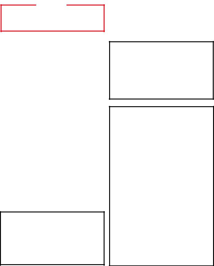
COMPRESSOR WINDING TEST
(See Figure 2.)
Remove the compressor terminal box cover and disconnect the wires from the terminals. Using an ohmmeter, check continuity across the following:
FIGURE 2 COMPRESSOR WINDING TEST
Line Voltage Overload
The compressor is equipped with an internal line voltage overload. This overload is embedded in the windings of the motor to sense the motor temperature. The overload will open and disconnect the power to the motor due to high temperatures caused by:
1.A locked rotor.
2.Excessive running amps.
3.High discharge temperature.
4.Low refrigerant charge.
FIGURE 1 INTERNAL OVERLOAD
LINE BREAK
INTERNAL OVERLOAD
OHMMETER
Testing Procedures
1.Terminal "C" and "S" - no continuity - open winding - replace compressor.
2.Terminal "C" and "R" - no continuity - open winding - replace compressor.
3.Terminal "R" and "S" - no continuity open winding - replace compressor.
4.Terminal "C" and the shell of the compressor – continuity – grounded motor – replace compressor.
5.Should continuity exist between terminals "R" and "S", but not between terminals "C" and "S" and "C" and "R", the internal overload may be open. If the compressor is extremely hot, allow it sufficient time to cool. It may require as long as one hour for the compressor to cool sufficiently for the internal overload to close.
4
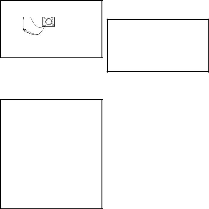
GROUND TEST |
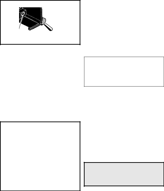
FAN MOTOR (Figure 4) |
Use an ohmmeter set on its highest scale. Touch one lead to the compressor body (clean point of contact, as a good connection is a must) and the other probe in turn to each compressor terminal. (See Figure 3.) If a reading is obtained, the compressor is grounded and must be replaced.
FIGURE 3 TYPICAL GROUND TEST
CHECKING COMPRESSOR EFFICIENCY
The reason for compressor inefficiency is normally due to broken or damaged suction and/or discharge valves, reducing the ability of the compressor to pump refrigerant gas.
This condition can be checked as follows:
1.Install a piercing valve on the suction and discharge or liquid process tube.
2.Attach gages to the high and low sides of the system.
3.Start the system and run a "cooling or heating performance test."
If test shows:
A.Below normal high side pressure.
B.Above normal low side pressure.
C.Low temperature difference across the coil.
The compressor valves are faulty - replace the compressor.
A 230 volt single phase permanent split capacitor motor is used to drive the evaporator blower and condenser fan. A running capacitor is wired across the start and run terminals of the motor. The motor is totally enclosed and is protected with a line voltage overload located internally of the motor. The motor shaft is stainless steel to resist corrosion.
FIGURE 4 FAN MOTOR
FAN MOTOR – TEST
Disconnect power to the unit.
1.Determine that the capacitor is serviceable.
2.Disconnect the black lead from the circuit board.
3.Apply "live" test cord leads to the common terminal of the capacitor and the black lead.
The motor should run at high speed.
5
SYSTEM CONTROL SWITCH
(Figure 5)
This switch is double pole, single throw. Check for continuity between terminals 2 and 3, and 5 and 6.
FIGURE 5 SWITCH, ON-OFF
CAPACITOR, RUN
A run capacitor is wired across the auxiliary and main winding of a single phase permanent split capacitor motor such as the compressor and fan motors. A single capacitor can be used for each motor or a dual rated capacitor can be used for both.
The capacitor’s primary function is to reduce the line current while greatly improving the torque characteristics of a motor. The capacitor also reduces the line current to the motor by improving the power factor of the load. The line side of the capacitor is marked with a red dot and is wired to the line side of the circuit. (See Figure 6.)
FIGURE 6 RUN CAPACITOR HOOK–UP
COMPRESSOR
FAN
MOTOR
RED DOT
RUN CAPACITOR
CAPACITOR – TEST
1.Remove the capacitor from the unit.
2.Check for visual damage such as bulges, cracks, or leaks.
3.For dual rated capacitors, apply an ohmmeter lead to the common (C) terminal and the other probe to the compressor (HERM) terminal. A satisfactory capacitor will cause a deflection on the pointer, then gradually move back to infinity.
4.Reverse the leads of the probe and momentarily touch the capacitor terminals. The deflection of the pointer should be two times that of the first check if the capacitor is good.
5.Repeat steps 3 and 4 to check the fan motor capacitor.
NOTE: A shorted capacitor will indicate a low resistance and the pointer will move more to the “0” end of the scale and remain there as long as the probes are connected. An open capacitor will show no movement of the pointer when placed across the terminals of the capacitor.
THERMOSTAT
A cross ambient |
|
thermostat is used |
|
to maintain the desired |
|
comfort level. The |
|
thermostat reacts only |
|
a change in temperature |
|
at the bulb location. |
|
Important to the |
|
successful operation |
|
of the unit is the position |
FIGURE 7 |
of the sensing bulb in |
SENSING BULB |
relation to the evaporator. |
LOCATION |
|
|
See Figure 7. |
|
RANGE:
Thermostat
(Part No. 618-225-02)
60° F ( ± 2° ) to 90° F( ± 4° )
6
 Loading...