


 Loading...
Installation and Operation Manual
PTAC
Packaged Terminal Air
Conditioners & Heat Pumps
FreshAireTM

Table of Contents
Congratulations········································································································································ 3 General Instructions·································································································································· 3 General Specifications·······························································································································4 PTAC Installation Recommendations··········································································································· 5 Wall Sleeve Installation Instructions (PDXWSA)···························································································· 6 Alternate Wall Installations························································································································· 7 PXDR10 Drain Kit Installation Instructions (optional for new construction)························································10 External Drain (for new construction or unit replacement)·············································································· 11 PXGA Standard Grille Installation Instructions····························································································· 12 Chassis Install Preparation······················································································································· 16 Chassis Installation································································································································· 18 Friedrich PTAC Digital Control and Unit Features·························································································19 System Configuration······························································································································ 21 Digital Control User Input Configuration······································································································ 22 Digital Control Operation·························································································································· 24 Remote Control Thermostat Installation······································································································ 26 Remote Thermostat and·························································································································· 26 Low Voltage Control Connections·············································································································· 26 Final Inspection & Start-up Checklist·········································································································· 28 Basic Troubleshooting····························································································································· 29 Service & Assistance······························································································································· 31 Accessories··········································································································································· 32
NOTE:
All PTAC 9000units come with a universal 2.5+1.0kW electric heater(standard 20A power cord for 3.5kW ,optional 15A power cord for 2.5kW). All PTAC 12000units come with a universal 3.5+1.5kW electric heater(standard 20A power cord for 3.5kW,optional 30A power cord for 5kW,optional 15A power cord for 1.5kW).
2
Congratulations
Thank you for your decision to purchase Friedrich. Your new Friedrich has been carefully engineered and manufactured to give you many years of dependable, efficient operation, maintaining a comfortable temperature and humidity level. Many extra features have been built into your unit to assure quiet operation, the greatest circulation of cool, dry air, and the most economic operation.
General Instructions
This Installation and Operation Manual has been designed to insure maximum satisfaction in the performance of your unit. For years of trouble-free service, please follow the installation instructions closely. We cannot overemphasize the importance of proper installation.
 WARNING
Refrigeration system under high pressure
Do not puncture, heat, expose to flame or incinerate.
Only certified refrigeration technicians should service this equipment.
R410A systems operate at higher pressures than R22 equipment. Appropriate safe service and handling practices must be used.
Only use gauge sets designed for use with
R410A. Do not use standard R22 gauge sets.
Here are some suggestions to help you use your new Friedrich most efficiently:
1.Carefully read and follow the installation instructions.
2.Make sure the unit is the right capacity for the area being cooled.
An undersized unit makes the unit work too hard, using more electricity than needed and increases wear. An oversized unit will cycle on and off too rapidly, and therefore cannot control humidity as well.
3.Clean the filter frequently (See Routine Maintenance, Page 27).
4.Do not block the air flow to and from the unit.
5.A dirty filter or improperly set controls can affect the cooling ability of the unit.
6.If cooling is weak and you have verified that the filter is clean
and the controls are properly set, the unit may need service and you should call your Friedrich service provider to check the unit.
7.Keep blinds, shades and drapes closed on the sunny side of the room being cooled to reduce radiant heat.
8.Proper insulation helps your unit maintain the desired inside temperature.
9.Whenever possible, shade south and west facing windows.
10.Keep window coverings away from the unit to provide free air flow.
 WARNING
Read Installation Operation Manual
Please read this manual thoroughly prior to equipment installation or operation.
It is the installer’s responsibility to properly apply and install the equipment. Installation must be in conformance with the NFPA 70 -2008 National Electric Code or current edition, International Mechanic Code 2009 or current edition and any other applicable local or national codes.
Failure to do so can result in property damage, personal injury or death.
Your safety and the safety of others are very important.
We have provided many important safety messages in this manual and on your appliance. Always read and obey all safety messages.
This is a safety Alert symbol.
This symbol alerts you to potential hazards that can kill or hurt you and others. All safety messages will follow the safety alert symbol with the word “WARNING” or “CAUTION”. These words mean:
 WARNING
 CAUTION
Indicates a hazard which, if not avoided, can result in severe personal injury or death and damage to product or other property.
Indicates a hazard which, if not avoided, can result in personal injury and damage to product or other property.
All safety messages will tell you what the potential hazard is, tell you how to reduce the chance of injury, and tell you what will happen if the instructions are not followed.
NOTICE
Indicates property damage can occur if instructions are not followed.
3
GeneralSpecifications
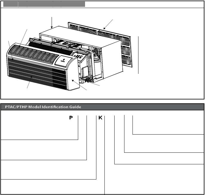
 Typical Unit Components and Dimensions
WALL SLEEVE
OUTDOOR GRILLE
DISCHARGE GRILLE
FILTERS
CHASSIS
RETURN AIR GRILLE |
FRONT COVER |
|
PDXWS Wall Sleeve Dimensions: 16" H x 42" W x 13-¾" D
Front Cover Dimensions: 16" H x 42" W x 7-¾" D
Cut-Out Dimensions: 16-¼" x 42-¼"
3 F A
Engineering Digit
Design Series
Chassis
F= FreshAire
Nominal Heater Size (230V or 265V)
3=3kW
Voltage
K = 230/208V - 1 Ph. - 60 Hz.
R = 265V - 1 Ph. - 60 Hz.
InstallationChecklist
. Inspect all components and accessories for damage before and after installation.
. Remove the cardboard wall sleeve support and grill weatherboard.
. Check for proper wall sleeve installation in accordance with the wall sleeve installation instructions.
. Check for a subbase kit or other means of structural support which is required for ALL installations projecting more than 8" into room.
. Install the recommended Condensate Drain Kits for complete condensate removal.
. Ensure that the chassis is installed in a 16" highx4'' wide wall sleeve
that is no deeper than 13-¾".A baffle kit is required if the sleeve exceeds that depth.
. Ensure that chassis and chassis front cover are installed and secured properly.
. Ensure that drapes,bed,bedspread,furniture,etc DO NOT block either return or discharge air grilles.
. Inspect the condenser air inlet and outlet for any obstructions
(shrubbery,etc).
. Ensure that 'reset' button is pressed on LCD device(only on cord connected models).
4
PTACInstallationRecommendations
For proper PTAC unit performance and maximum operating life refer to the minimum installation clearances below:
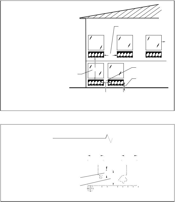
Figure 1
PTAC units should be installed no closer than 12" apart when two units are side by side. If three or more PTAC units are to operate next to one another allow a minimum of 36" between units. Also,a vertical clearance of 60" should be maintained between units installed. In the interior of the room the unit should be located a minimum of 1/4" from the floor and a minimum of 36" from the ceiling.
THREE OR MORE PTACs
ADJACENT 36" MINIMUM
TYPICAL
WINDOW
36"
60" |
TWO ADJACENT PTACs |
|
12" MINIMUM |
||
|
60" VERTICAL |
|
|
MINIMUM |
GROUND FLOOR PTACs |
|
BETWEEN |
||
6" MINIMUM FROM GRADE |
||
PTACs |
||
|
||
12" |
6" |
VIEW: OUTSIDE BUILDING ELEVATION
FRP001
For PTACs on the ground floor or anytime obstructions are present, use the following guidelines:
Figure 2
•For minor obstructions such as lamp poles or small shrubbery a clearance of
12" from the outdoor louver should be maintained.
•For major obstructions such as a solid fence, wall or other heat rejecting device like a condensing unit, a minimum distance of 36" should be kept.
|
|
|
|
|
|
|
|
|
|
|
|
|
|
|
|
|
|
|
|
|
|
|
|
|
|
|
|
|
|
|
|
|
TYPICAL BUILDING ( PLAN VIEW ) |
|
|
||||||||||||||||
|
|
|
|
|
|
|
|
|
|
|
36" |
|
|
|
|
|
|
|
|
36" |
|
|
|
|
|
|
|
|
|
|
|
|
|
|
|
|
|
|
|
|
|
|
|
|
|
|
|||||
|
|
|
|
|
|
|
|
|
|
|
|
|
|
|
|
|
|
|
|
|
|
|
|
|
|
|
|
|
|
|
|
|
|
|
|
|
|
|
|
|
|
|
|
|
|
|
|
|
|
|
|
|
|
PTAC |
|
|
|
|
|
|
|
|
|
PTAC |
|
|
|
|
|
PTAC |
|
|
|||||
|
|
|
|
|
|
|
|
|
|
|
|
|
|
|
|
||||||||||
|
|
|
|
|
|
|
|
|
|
|
|
|
|
|
|
|
|
|
|
|
|
|
|
|
|
12" MINIMUM, MINOR |
|
|
|
|
|
|
|
|
|
|
12" |
|
|
SHRUB |
|
|
|
||||||||
|
|
|
|
|
|
|
|
|
|
|
|
|
|
|
|||||||||||
|
|
|
|
|
|
|
|
|
|
|
|
|
|
|
|
|
|
||||||||
|
|
|
POLE |
|
|
36" |
|
|
|
||||||||||||||||
|
|
|
|
|
|
|
|
|
|
|
|||||||||||||||
OBSTRUCTIONS |
|
|
|
|
|
|
|
|
|
|
|
|
|
|
|
|
|
|
|
||||||
36" MIMUMUM, MAJOR |
|
|
|
|
|
|
|
|
|
|
|
|
|
|
|
|
|
|
|
|
|
||||
|
|
|
|
|
|
|
|
|
|
|
|
|
|
|
|
|
|
|
|||||||
|
|
|
|
|
|
|
|
|
|
|
|
|
|
|
|
|
|
|
|
||||||
OBSTRUCTIONS |
|
|
|
|
|
|
|
|
|
FENCE OR WALL |
|
|
|||||||||||||
CONDENSING UNIT
FRP002
The above suggestions are for reference only and do not represent all possible installations.Please contact Friedrich for information regarding affects of other installation arrangements.By following these simple recommendations you can be confident that your Friedrich PTAC will provide years of worry free operation.
5
Wall Sleeve Installation Instructions (PDXWSA)
NOTE: Insure that the unit is only installed in a wall structurally adequate to support the unit including the sleeve, chassis and accessories.If the sleeve projects more than 8" into the room, a subbase or other means of support MUST be used. Please read these instructions completely before attempting installation.
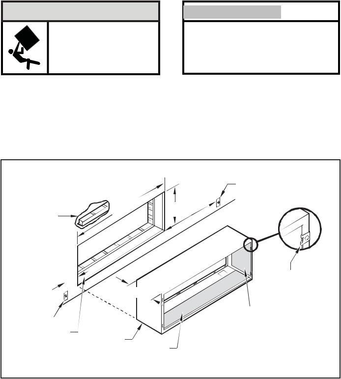
 WARNING
Falling Object Hazard
Not following Installation Instructions for mounting your air conditioner can result in property damage, injury, or death.
NOTICE 
DO NOT allow any pitch toward the inside.
Flashing on all 4 sides of the opening is recommended.
Potential property damage can occur if instructions are not followed.
For Deep Wall Installation (Greater than 13 1/4")
See Page 9
The following instructions apply ONLY to walls less than 13 ¼" in depth.
1The PXDR10 Drain Kit,(optional for new construction) see page 10 if applicable, must be installed before the wall sleeve is installed into the wall.
2The External Drain (for new construction or unit replacement) see page 11 if applicable, must be installed before the wall sleeve is installed into the wall.
Figure 3
Typical Wall Sleeve Installation
3From inside the building, position the wall sleeve in the opening and push it into the wall until it protrudes at least ¼” on the outside (See Figure 9, Page 8).
4Position the wall sleeve with a slight tilt towards the outside to facilitate condensate drainage. It should be level side-to-side and the front should be ¼ bubble higher than the back.
ELECTRICAL
RECEPTACLE
|
42-¼" |
16-¼" |
|
|
|
LINTEL TO SUPPORT |
60" |
|
|||
MIN. |
|
||||
|
|
MAX. |
|
||
MASONRYWALLS |
|
|
|
|
|
|
|
|
|
|
|
20"
MAX. |
|
|
SMOOTH SIDE OF SCREW |
|||
|
|
|
|
13-¾" |
|
CLIP FACING INTO ROOM |
|
|
|
|
|
INSULATION |
|
ELECTRICAL |
|
|||||
|
|
|||||
|
|
|||||
|
|
|
||||
RECEPTACLE |
|
|
|
|
|
|
|
|
|
|
|
||
WALL OPENING
WALL SLEEVE
INSULATION
NOTE: All 230/208V units are manufactured with a 60” power cord and all 265V units with a 18” power cord.
FRP003
6

AlternateWall Installations
Figure 4
Panel Wall
OPTIONAL SUBBASE
LEVELING SCREW
FRP004
Figure 5
Frame and Brick Veneer
1/4" MIN PROJECTION
WOOD FRAME
STEEL
LINTEL
 11" MIN.
WITH SUBBASE
OPTIONAL SUBBASE
LEVELING SCREW
FRP005
Figure 6
CurtainWall
WALL OR |
1/4" MIN |
WINDOW |
PROJECTIO |
|
N |
CASE FLANGE (BY OTHERS)
OPTIONAL SUBBASE
LEVELING SCREW
FRP006
Figure 7
Block and Brick Veneer
1/4" MIN PROJECTION
CONCRETE LINTEL
STEEL
LINTEL
13-3/4" MIN. WITHOUT SUBBASE
RECEPTACLE
FINISHED FLOOR |
POWER SUPPLY CONDUIT |
|
(SUPPLIED BY INSTALLER) |
||
|
||
|
FRP007 |
NOTE: |
Follow all wall system manufacturer installation instructions. For sunrooms and modular buildings, adhere to their installation instructions for |
|
supporting and sealing sleeve to their frames. All wall and window/wall installations must provide for proper drainage. In applications where the |
|
drain holes on the PTAC wall sleeve are not exposed beyond the wall an internal drain system is recommended. It is the installer's responsibility |
|
to ensure there is adequate drainage for the PTAC unit. |
7
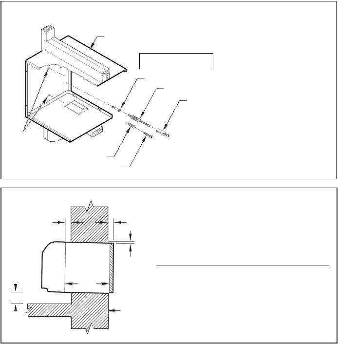
Figure 8
Wall Sleeve Attachment
WALL
SLEEVE
MOUNTING
HOLES
PLASTIC ANCHORS
SCREWS
ALTERNATE FASTENING METHODS (Field Supplied)
|
|
NOTE: The Wall Sleeve must be |
|
|
|
|
|
horizontally level (side-to-side) |
WOOD SCREW |
and pitched 1/4 bubble to the |
|
outside when installed in an |
||
TOGGLE BOLT |
opening. |
|
The mounting hole location
EXPANSION |
should be approximately 2-4” |
|
ANCHOR BOLT |
||
from the top and bottom of the |
||
|
||
|
sleeve. |
FRP008
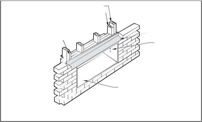
Figure 9
Dimensions
A |
¼" MIN. |
C
13-¾"
B
WALL
|
A |
|
B |
C |
Dimension* |
Allow |
Allow |
Allow |
|
|
for wall |
for floor |
for proper |
|
|
finishing |
finishing |
drainage |
|
|
(Minimum) |
Min. |
Max. (Front-to-Back) |
|
No Accessories |
¼" |
¼" |
--- |
--- |
With Subbase |
1-¾" |
3-½" |
5" |
--- |
With Lateral Duct |
¾" |
¼" |
--- |
--- |
|
|
|
|
|
Wall Sleeve Tilt |
--- |
--- |
--- |
¼" |
|
|
|
|
|
*If more than one accessory is to be used, use the maximum dimension. If the wall thickness is more than 13-¾" - (A+ ¼"), a sleeve extension must be used.
FRP009
8
5.Drill two 3/16" holes through each side of the sleeve approximately
4" from top and 4" from bottom of sleeve. Screw four #10 x 1" screws (included) or appropriate fasteners for your installation, through the holes in the sides of the wall sleeve.
6.Apply sealant around the wall sleeve where it projects through the inside and outside wall surfaces. Apply the sealant to the screw heads or the tops of the fasteners used in Step #5.
Figure 10 |
MAIN STUDS |
||
Lintel Installation |
|||
|
|
||
JACK STUDS |
|||
|
|||
JACK STUDS 
MAIN STUDS 
7.If the chassis and exterior grille are to be installed later, leave the weatherboard and center support in place, otherwise remove and dispose of them. (See Figure 13, Page 12).
8.Provide a support lintel if the wall sleeve is installed in a concrete or masonry wall (See Figure 10, Page 9).
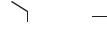 LINTEL
MOUNTING
SCREW HOLES
NO HOLES IN BOTTOM OF WALL
SLEEVE UNLESS DRAIN KIT IS USED
NOTE: Construct wall opening to comply with all applicable building codes.
FRP010
One-Piece Deep Wall Sleeve Installation (PDXWSEXT)
If the wall is thicker than 13 1/4” a deep wall sleeve or wall sleeve extension
MUST be used. The deep wall sleeve may be special ordered through your Sales Representative.
9
PXDR10DrainKitInstallation Instructions(optionalfornew construction)
NOTE: Determine whether drain will be located within the wall, on the indoor side, or will drain to the exterior of the building. Follow appropriate instructions below depending on your particular type of installation.
InternalDrain
NOTE: If installing an internal drain, you MUST install a drain kit on the wall sleeve before the wall sleeve is installed.
1.Refer to Figure 11 and locate the drain within the “Preferred” area of best drainage.Maintain at least a ½” clearance from the embossed area.
2.Using the mounting plate with the ½” hole as a template, mark and drill two, 3/16” mounting holes and a ½” drain hole in the sleeve bottom.
Figure 11
DrainKitLocationandInstallation
OPTIONAL AREA
PREFERRED AREA-
NO FOAM INSULATION
IF THE DRAIN MUST BE |
|
LOCATED IN THE OPTIONAL |
|
AREA, THE FOAM INSULATION |
|
MUST BE CUT AWAY AND |
3" |
REMOVED TO ALLOW ACCESS |
|
TO THE DRAIN. |
|
3.Remove the backing from the gasket and mount it on the flat side of the mounting plate (See Figure 12, Page 11). Insert the drain tube through the hole in the gasket and mounting plate so the tube flange will be against the wall sleeve.
4.Position the assembly beneath the drilled holes and secure it with
#10-24 x ½" machine screws and lock nuts provided. Seal the tops of the screws with silicone caulking.
5.Use ½" I D copper tube, PVC pipe, or vinyl hose (obtained locally) to connect the internal drain tube to the drain system in the building.
6.Referring to Figure 12, Detail A, Page 11, locate and assemble the two cover plates and gaskets over the drain holes at the rear of the wall sleeve. Attach them with the #10 sheet metal screws provided. Make certain that the four overflow slots at the rear of the wall sleeve are not blocked (See drawing of the back of the sleeve Figure 12, Page 11).
7.If a deep wall extension (PDXWSEXT) is used, after installing the field supplied flashing,caulk as required. Be sure to caulk around the flashing and the wall sleeve where the hole was drilled for the drain tube.
SCREW
WALL SLEEVE

 GASKET
MOUNTING
PLATE
DRAIN TUBE |
|
|
|
|
|
|
|
|
|
|
|
|
|
|
|
NUT |
|
|
|||||
|
|
|
|
SIDE VIEW
|
|
|
|
|
|
|
|
|
|
|
|
|
|
|
|
|
|
|
|
|
|
|
|
|
|
|
|
|
|
|
|
|
|
|
|
|
|
|
|
|
|
|
|
|
|
|
|
|
|
|
|
|
|
|
|
|
|
|
|
|
|
|
|
|
|
|
|
|
|
|
|
|
|
|
|
|
|
|
|
|
|
|
|
|
|
|
|
|
|
|
|
|
|
|
|
|
|
|
|
|
|
|
|
|
|
|
|
|
|
|
|
|
|
|
|
|
|
|
|
|
|
|
|
|
|
|
|
|
|
|
|
|
|
|
|
|
|
|
|
|
|
|
|
|
|
|
|
|
|
|
|
|
|
|
|
|
|
|
|
|
|
|
|
|
|
|
|
|
|
|
|
|
|
|
|
|
|
|
|
|
|
|
|
|
|
|
|
|
|
|
|
|
|
|
|
|
|
|
|
|
|
|
|
|
|
|
|
|
|
|
|
|
|
|
|
|
|
|
|
|
|
|
|
|
|
|
|
|
|
|
|
|
|
|
|
|
|
|
|
|
|
|
|
|
|
|
|
|
|
|
|
|
|
|
|
|
|
|
|
|
|
|
|
|
|
|
|
|
|
|
|
|
|
|
|
|
|
|
|
|
|
|
|
|
|
|
|
|
|
|
|
|
|
|
|
|
|
|
|
|
|
|
|
|
|
|
|
|
|
|
|
|
|
|
|
|
|
|
|
|
|
|
|
|
|
|
|
|
|
|
|
|
|
|
|
|
|
|
|
|
|
|
|
|
|
FRONT VIEW |
|||||||||||||||||
|
|
|
|
|
|
|
|
|
|
|
|
|
|
|
|
|
|
|
|
|
|
|
|
|
FRP011 |
|
|
|
|
|
|
|
|
|
|
|
|
|
|||||||||||||
|
|
|
|
|
|
|
|
|
|
|
PXDR10 |
||||||||||||||
QUANTITY |
|
|
|
|
|
|
|
|
|
DESCRIPTION |
|||||||||||||||
2 |
|
|
|
|
|
COVER PLATES |
|||||||||||||||||||
1 |
|
|
|
|
|
MOUNTING PLATE |
|||||||||||||||||||
1 |
|
|
|
|
|
DRAIN TUBE |
|||||||||||||||||||
3 |
|
|
|
|
|
MOUNTING PLATE GASKET |
|||||||||||||||||||
4 |
|
|
|
|
|
#10 X ½” SHEET METAL SCREWS |
|||||||||||||||||||
2 |
|
|
|
|
|
#10-24 X ½ ” MACH. SCREWS |
|||||||||||||||||||
2 |
|
|
|
|
|
#10-24 X ½" LOCKNUTS |
|||||||||||||||||||
10
External Drain (for new construction or unit replacement)
When using an external drain system, the condensate is removed through either of two drain holes on the back of the wall sleeve. Select the drain
hole which best meets your drainage situation and install the drain kit.
Seal off the other with a cover plate.
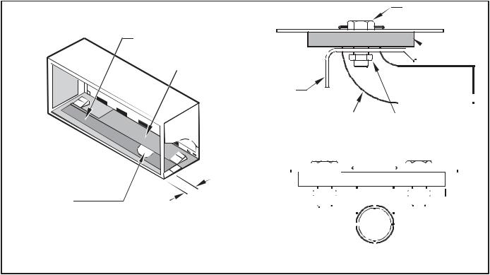
Drain Tube Installation (See Figure 12)
Cover Plate Installation
4.Mount the foam gasket to the cover plate. Using two #10 x ½" sheet metal screws (provided), attach the cover plate to the remaining drain hole. Make certain the large flange on the plate is positioned at the bottom of the sleeve.
5.Discard the additional cover plate, gasket, machine screws, and locknuts.
NOTICE 
1.Peel the backing tape off the gaskets and apply the sticky side to one cover plate and one mounting plate as shown in Details A and B.
2.Place the drain tube through the gasket and the mounting plate with the flange toward the wall sleeve.
3.Attach the drain tube assembly to one of the two drain holes at the rear of the wall sleeve. The large flange on the mounting plate is positioned at the bottom of the sleeve facing toward the sleeve, Detail B. When the drain tube is positioned at the desired angle, tighten the screws.
If the wall sleeve has not been installed, the drain tube must be rotated to a horizontal position until after the sleeve is installed. Tighten the mounting plate screws when the tube is in the proper position. Make certain that the four overflow slots at the rear of the wall sleeve are not blocked (See Figure 12).
When sealing the sleeve on the outside of the building, be careful NOT to let the sealant block the two condensate drain holes or the four overflow slots at the bottom flange of the sleeve.
Potential property damage can occur if instructions are not followed.
Figure 12 |
COVER |
Drain Kit Installation |
PLATE |
|
MOUNTING
PLATE FOAM GASKET
DETAIL A
NUT
OVERFLOW
SLOTS
SCREWS
FOAM
GASKET
½” O.D. TUBE
DETAIL B
FRP012
NOTE: The large flange on the mounting plate is positioned at the bottom of the sleeve facing toward the sleeve. The drain tube must be rotated to a horizontal position to allow for the wall sleeve to be installed into the wall. Once the wall sleeve is installed, return the drain tube to a downward angle.
11
Loading...