


YS12M33
Friedrich YS12M33, YS10M10, YM18M34, YL24M35, ES15M33 User Manual
...
Room Air Conditioners
AUTO
°F°C
AUTO
CONTINUOUS
AUTO
SYSTEM FAN MODE
SCHEDULE FAN SPEED
Installation and Operation Manual
Standard Chassis Models
115-Volt:
208-230-Volt:
115-Volt:
208-230-Volt:
920-198-00 (11-09)
SS08M10, SS10M10, SS12M10, SS14M10
SS12M30, SS15M30, SM18M30, SM21M30
SL2 5M30, SL28M30, SL 36M30
YS10M10
ES12M33, ES15M33, YS12M33, EM18M34,
YM18M34, EL25M35, EL36M35, YL24M35
wwwwww.sylvane.com 1 (800) 934-9194
920-198-00
Congratulations!
Thank you for your decision to purchase the Friedrich High Effi ciency Air Conditioner. Your new Friedrich has been carefully engineered and manufactured to
give you many years of dependable, effi cient operation, maintaining a comfortable temperature and humidity level. Many extra features have been built into
your unit to assure quiet operation, the greatest circulation of cool, dry air, and the most economic operation.
THANK YOU, on behalf of our entire company,
for making such a wise purchase.
AIR CONDITIONING CO.
SAN ANTONIO, TEXAS
ASSEMBLED IN MEXICO
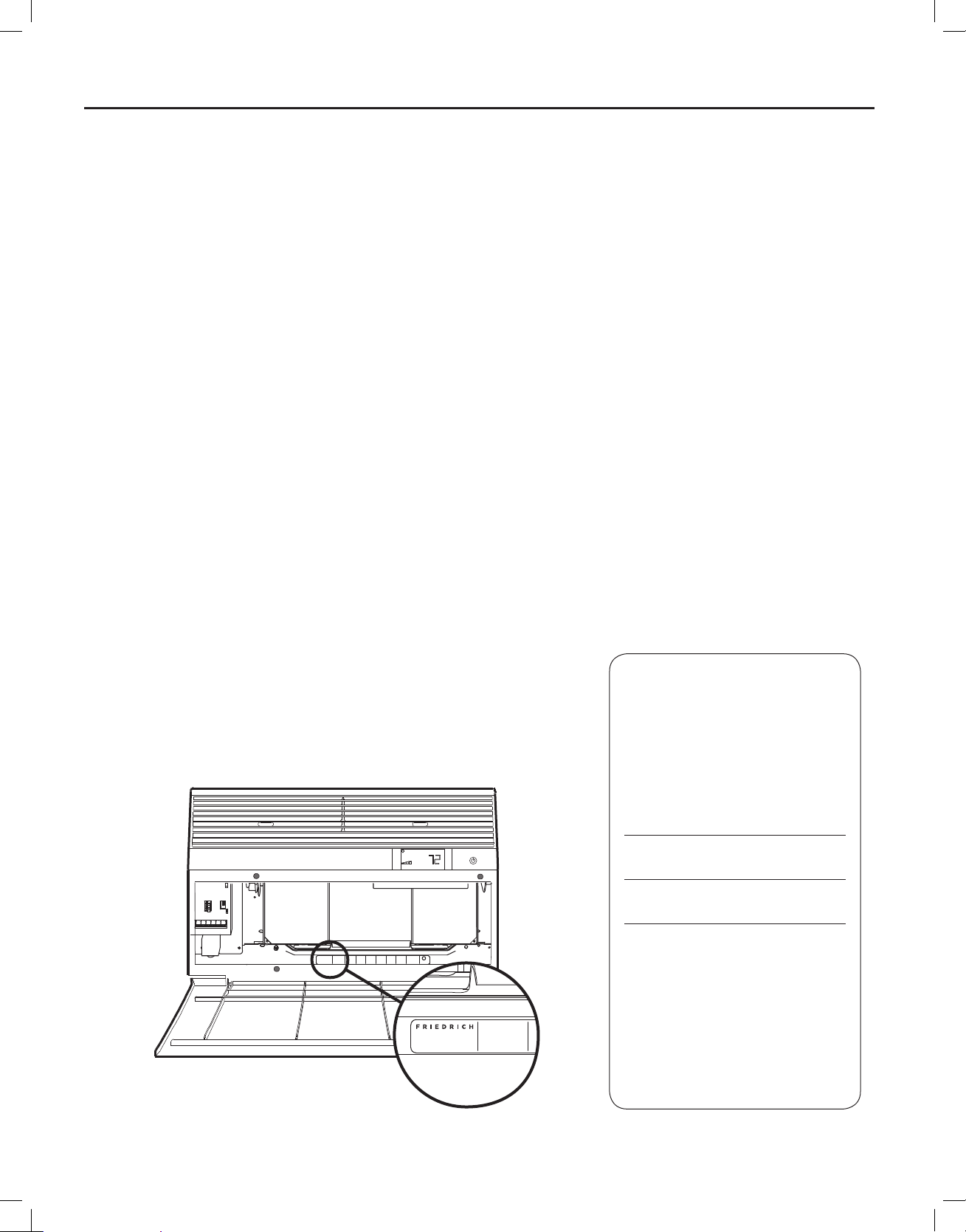
Register your air conditioner
Model information can be found on the name
plate behind the front cover.
Please complete and mail the owner
registration card furnished with this product,
or register online at www.friedrich.com (USA
only). For your future con ve nience, record the
model information here.
MODEL NUMBER
SERIAL NUMBER
PURCHASE DATE
COOLING
VOLTS 115
MODEL NUMBER
HEATING
REFRIGERANT
XXXXXXXXX
XXXXXXXXXX
FUSE PROTECTED
U
600 PSIG HS
XXXXXXXXX
CIRCUITS USE 15A
300 PSIG LS
XXXXXXXXXX
TIME DELAY FUSE
XXXXXXXXXX
L
X XX
XXXXX
XXXXXXXXXX
AIR CONDITIONING CO.
SAN ANTONIO, TEXAS
ASSEMBLED IN MEXICO
MODEL NUMBER
YS10M10A
SERIAL NUMBER
LICY00008
BTH/HR 6500
60 HZ / 1 PH
YS10M10A
BTH/HR 6500
30.1 OZ R410A
EER 12.0
VOLTS MIN 108
SERIAL NUMBER
EER 10.4
AMPS 8.0
LICY00008
AMPS 7.0
2
wwwwww.sylvane.com 1 (800) 934-9194

920-198-00
Table of Contents
Safety Precautions ................................................................................................................................................................................................................... 4
Unpacking Instructions............................................................................................................................................................................................................. 5
WARNING: Before Operating Your Unit ..................................................................................................................................................................................6
Standard Filter Cleaning / Installation Instructions .................................................................................................................................................................. 7
Premium Carbon Filter Installation Instructions ....................................................................................................................................................................... 8
Control Panel Operation ........................................................................................................................................................................................................ 10
Add a Remote Thermostat ..................................................................................................................................................................................................... 14
Remote Thermostat Selection ............................................................................................................................................................................................... 14
Remote Control Operation ..................................................................................................................................................................................................... 15
Remote Effectiveness ............................................................................................................................................................................................................ 15
Airfl ow Selection and Adjustment .......................................................................................................................................................................................... 17
Installation Instructions .......................................................................................................................................................................................................... 18
Standard Window Installation ................................................................................................................................................................................................ 20
Cord Routing Change ............................................................................................................................................................................................................ 30
Through-the-Wall Installation ................................................................................................................................................................................................. 32
Programmable Thermostat ....................................................................................................................................................................................................36
Final Inspection & Start-up Checklist..................................................................................................................................................................................... 38
Routine Maintenance ............................................................................................................................................................................................................. 39
Service and Assistance ......................................................................................................................................................................................................... 39
Available Accessories ............................................................................................................................................................................................................ 39
Troubleshooting Tips .............................................................................................................................................................................................................. 40
Addendum 1 ........................................................................................................................................................................................................................... 42
wwwwww.sylvane.com 1 (800) 934-9194
3
Safety Precautions
We have provided many important safety messages in this manual and on your appliance. Always read and obey all
safety messages.
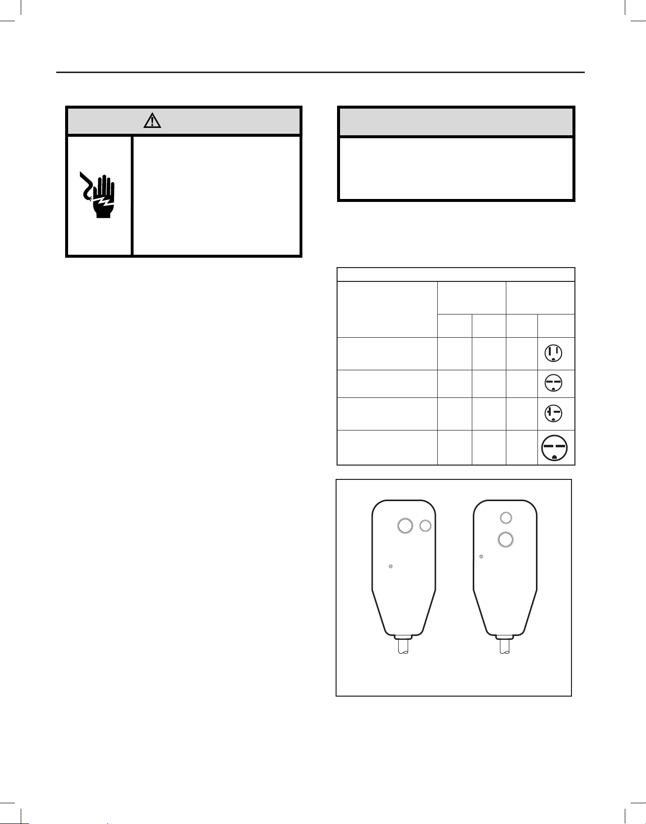
WARNING
CAUTION
All safety messages will tell you what the potential hazard is, tell you how to reduce the chance of injury, and tell you
what will happen if the instructions are not followed.
920-198-00
Your safety and the safety of others are very important.
This is a safety Alert symbol.
This symbol alerts you to potential hazards that can kill or hurt you and others.
All safety messages will follow the safety alert symbol with the word “WARNING”
or “CAUTION”. These words mean:
Indicates a hazard which, if not avoided, can result in severe personal injury or
death and damage to product or other property.
Indicates a hazard which, if not avoided, can result in personal injury and
damage to product or other property.
NOTICE
Indicates property damage can occur if instructions are not followed.
WARNING
Refrigeration system
under high pressure
Do not puncture, heat, expose to flame or
incinerate.
Only certified refrigeration technicians should
service this equipment.
R410A systems operate at higher pressures
than R22 equipment. Appropriate safe
service and handling practices must be used.
Only use gauge sets designed for use with
R410A. Do not use standard R22 gauge sets.
4
wwwwww.sylvane.com 1 (800) 934-9194
920-198-00
'5$:1
&+(&.('
4$
0)*
$33529('
HKHUQDQGH]
7,
6
67(3
67(3
67(3
67(3
67(3
67(3
67(3
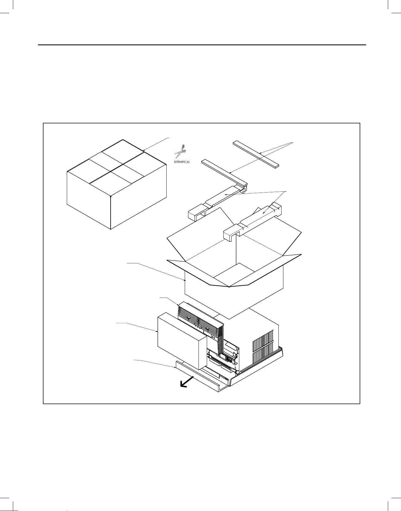
Unpacking Instructions
STEP 1. Cut all 4 packing straps.
STEP 2. Remove wooden shipping bar dividers.
STEP 3. Remove top foam pads.
STEP 4. Slowly remove outer box, careful not to loosen decorative front.
STEP 5. Slide the foam front support forward
STEP 6. Carefully lift decorative front box from foam front support
STEP 7. Remove decorative front and set safely aside
wwwwww.sylvane.com 1 (800) 934-9194
5
920-198-00
WARNING: Before Operating Your Unit
WARNING
Electrical Shock Hazard
Make sure your electrical receptacle has the
same configuration as your air conditioner’s
plug. If different, consult a Licensed Electrician.
Do not use plug adapters.
Do not use an extension cord.
Do not remove ground prong.
Always plug into a grounded 3 prong oulet.
Failure to follow these instructions can result in
death, fire, or electrical shock.
Make sure the wiring is adequate for your unit.
If you hav e fus es, t hey sho uld b e of the t ime d ela y typ e. B efor e you ins tall
or relocate this unit, be sure that the amperage rating of the circuit breaker
or time delay fuse does not exceed the amp rating listed in Table 1.
DO NOT use an extension cord.
The cord provided will carry the proper amount of electrical power to the
unit; an extension cord may not.
Make sure that the receptacle is compatible with
the air conditioner cord plug provided.
Proper grounding must be maintained at all times. Two prong receptacles
must be replaced with a grounded receptacle by a certifi ed electrician.
The grounded receptacle should meet all national and local codes and
ordinances. You must use the three prong plug furnished with the air
conditioner. Under no circumstances should you remove the ground
prong from the plug.
Test the power cord
All Friedrich room air conditioners are shipped from the factory with a
Leakage Current Detection Interrupter (LCDI) equipped power cord. The
LCDI device on the end of the cord meets the UL and NEC requirements
for cord connected air conditioners.
To test your power supply cord:
1. Plug power supply cord into a grounded 3 prong outlet.
2. Press RESET (See Figure 1).
3. Press TEST, listen for click; the RESET button trips and pops out.
4. Press and release RESET (Listen for click; RESET button latches
and remains in). The power cord is ready for use.
NOTICE
Do not use the LCDI device as an ON/OFF switch.
Failure to adhere to this precaution may cause
premature equipment malfunction.
Once plugged in, the unit will operate normally without the need to reset
th e LC DI de vic e. If the LCD I dev ice f ail s to t rip w hen t est ed o r if t he po wer
su pply cord is da mag ed, i t mu st be repl aced with a ne w pow er s uppl y cor d
from the manufacturer. Contact our Technical Assistance Line at (800)
541-6645. To expedite service, please have your model number available.
Tabl e 1.
MODEL
SS08M10, SS10M10,
SS12M10, SS14M10,
YS10M10
SS12M30, SS15M30,
SM18M30, SM21M30
SL25M30, SL28M30,
ES12M33, ES15M33,
YS12M33
SL36M30, EM18M34,
EL25M35, EL36M35,
YM18M34, YL24M35
Figure 1
RESET
WARNING
TEST BEFORE EACH USE
1. PRESS RESET BUTTON
2. PLUG LCDI INTO POWER
RECEPTACLE
3. PRESS TEST BUTTON,
RESET BUTTON SHOULD
POP UP
4. PRESS TEST BUTTON,
FOR USE
DO NOT USE IF ABOVE TEST
FAILS
WHEN GREEN LIGHT IS ON
IT IS WORKING PROPERLY
CIRCUIT RATING
OR TIME DELAY
AMP VOLT
15 125 5-15R
15 250 6-15R
20 250 6-20R
30 250 6-30R
TEST
FUSE
TEST BEFORE EACH USE
1. PRESS RESET BUTTON
2. PLUG LCDI INTO POWER
RECEPTACLE
3. PRESS TEST BUTTON,
RESET BUTTON SHOULD
POP UP
4. PRESS TEST BUTTON,
FOR USE
DO NOT USE IF ABOVE TEST
FAILS
WHEN GREEN LIGHT IS ON
IT IS WORKING PROPERLY
REQUIRED
WALL
RECEPTACLE
NEMA
NO.
TEST
RESET
WARNING
15/20A LCDI Device 30A LCDI Device
FRR001
6
wwwwww.sylvane.com 1 (800) 934-9194
920-198-00
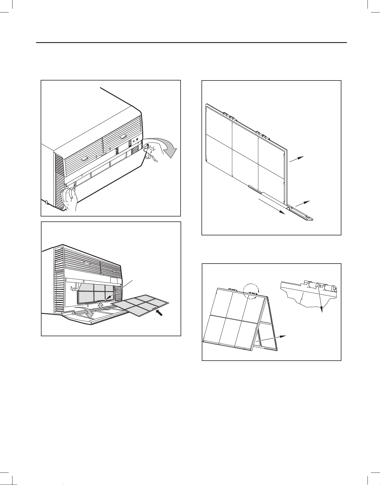
Standard Filter Cleaning / Installation Instructions
STEP 1. Swing the door open and remove the fi lter by grasping the
fi lter grip and pushing the fi lter holder upward and outward.
Figure 2
STEP 2. Slide the fi lter grip out from the fi lter as shown in Figure 4.
NOTE: Make sure the front frame with the mesh fi lter is facing you.
Figure 4
FILTER
FILTER
GRIP
Figure 3
FILTER
GRIP
FRR071
HANDLE
FRR052
FRR047
STEP 3. Swing the front frame open. Clean the front frame by washing
the dirt from the fi lter. Use a mild soap solution if necessary.
Allow fi lter to dry.
Figure 5
A
TOP TAB
FRONT
FRAME WITH
STANDARD
MESH FILTER
FRR048
STEP 4. Install the fi lter grip back into the fi lter by sliding it into the fi lter.
NOTE: The fi lter handle slides into the frame in only one direction. If
the tab in the frame stops the handle from sliding in, slide the
handle from the other direction. Do not force the handle into
the frame.
STEP 5. Install the fi lter back into the unit. Follow the Instructions on
the inside of the front door.
wwwwww.sylvane.com 1 (800) 934-9194
7
920-198-00
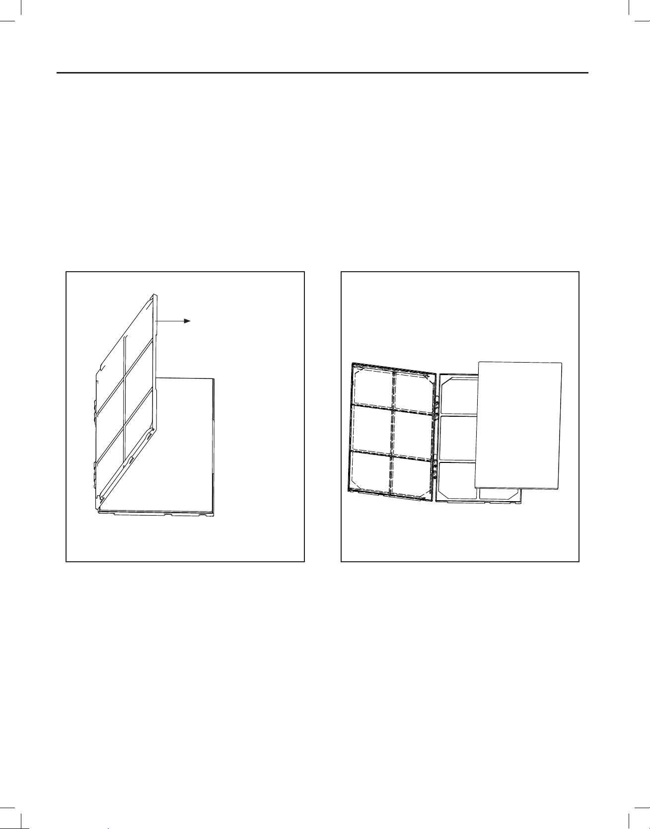
Premium Carbon Filter Installation Instructions
STEP 1. Remove the fi lter from the unit as per the instructions on the
inside of the fi lter door.
STEP 2. Hold the fi lter at the top and slide the fi lter grip out as shown
in Figure 4.
STEP 3. If you already have a carbon fi lter installed remove the dirty
fi lter by laying the fi lter down and swinging open the front frame
as shown in Figure 6.
NOTE: Make sure the frame with the mesh is facing towards you.
STEP 4. Place the new carbon fi lter on the top of the back fi lter frame.
The carbon fi lter has been cut to the correct dimension and
should fi t within the frame as shown in fi gure 7
NOTE: The carbon fi lter is not a re -usable fi lter, and needs to be replaced
every three months for optimum effi ciency.
STEP 5. Slide the fi lter handle back on to hold the frames together
and slide the assembly into the unit as per the instructions
on the door.
NOTE: The fi lter handle slides into the frame in only one direction. If
the tab in the frame stops the handle from sliding in, slide the
handle from the other direction. Do not force the handle into
the frame.
Figure 6
Figure 7
FRONT FRAME WITH
MESH FILTER
FRR051FRR050
8
wwwwww.sylvane.com 1 (800) 934-9194

920-198-00
THIS PAGE INTENTIONALLY LEFT BLANK
wwwwww.sylvane.com 1 (800) 934-9194
9
920-198-00
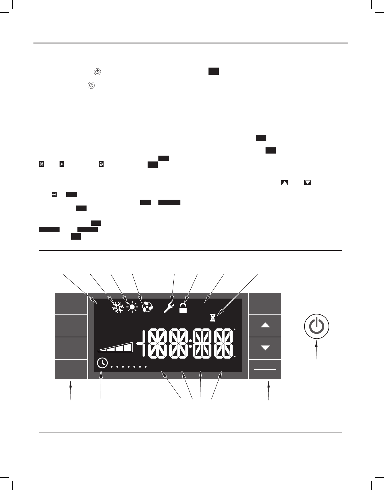
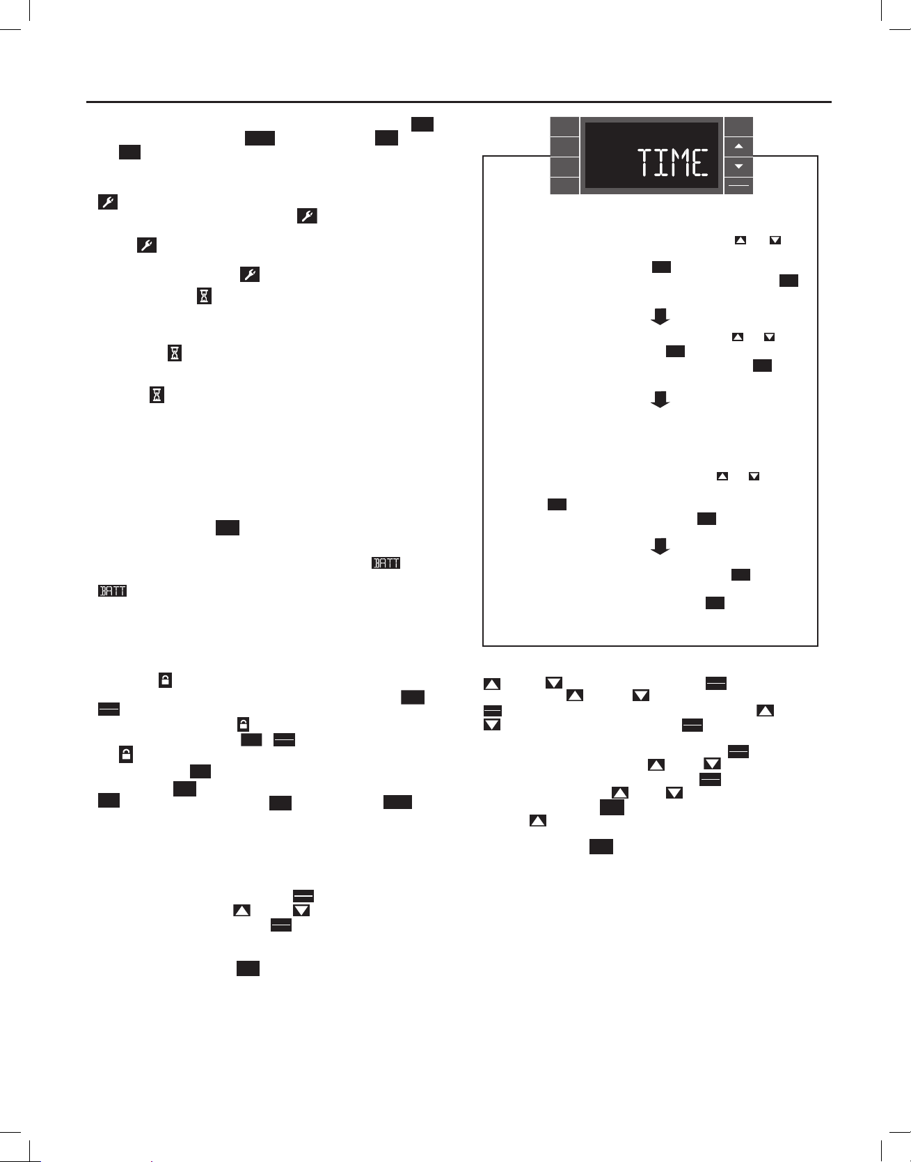
Control Panel Operation
Let’s check out how to control your air conditioner. On the control panel,
ju st t o the lef t o f th e POW ER
control panel function buttons and mode icons can be viewed in Figure 8.
Power On – Press the
power button will illuminate to indicate the power is on. The backlight on
the power switch will automatically dim to 20% intensity after 15 seconds
of inactivity. The remote control can also be used to turn power ON / OFF
(See Remote Control).
Display – The display is a high effi ciency LCD with a built-in white back
light. The back light has an automatic two (2) step dim function. After 15
seconds of inactivity, the display dims to 20% intensity. After an additional
120 seconds, the display switches off. Touching buttons will automatically
bring the display to full brightness.
There are four control push buttons on each side of the display.
SYSTEM Button – Allows the user to sequentially select,
, HEAT , and FAN ONLY operation. Press the
the display advances to the next mode. A new icon appears. At the same
time, the mode displays for two (2) seconds, then returns the display to
the temperature set point for modes other than FAN. Note that when the
heating function is not available, the system will automatically skip the
HEAT
and
AUTO
modes.
FAN MODE Button – Selects between automatic
operation. In the
AUTO
compressor operates or the heat function is enabled.
In the FAN ONLY Mode,
CONTINUOUS
. In the
selection on the
CONTINUOUS
FAN
SPEED
button.
Figure 8
AUTO
MODE
COOL
MODE
, is a liquid crystal display (LCD). All of the
button to turn on the air conditioner. The
AUTO
Cool
button and
CONTINUOUS
AUTO
SYSTEM
or
mode, the fan only turns on and off when the
AUTO
is not available. The display indicates
mode, fans speed is determined by your
HEAT
MODE
FAN
ONLY
MODE
MAINTENANCE
REQUIRED
FAN SPEED Button – Used to sequentially select between fan speeds.
Depending on your model, you can select between LOW, MED, HIGH,
and MAX and AUTO. Max setting not on SL or Kühl + models). When
FAN
the
button is pressed, the fan speed is temporarily displayed in the
SPEED
display window, plus a fan speed icon (triangle) changes to indicate the
new speed level when auto is selected. Fan speed automatically varies
depending on the set temperature on the control panel and the actual
room temperature. Let me explain. Say for example you’re working in
your garage and you need to open the big door for several minutes. The
air conditioner will sense a wide difference between the set temperature
and the actual room temperature when this occurs the system fan speed
increases to MAX. The fan speed decreases (in step) as the temperature
difference decreases. When the set point temperature is reached the FAN
speed returns to the original setting.
SCHEDULE Button – The
and off. The current day of the week is indicated as a dot underneath
the day symbol. Pressing the
SCHEDULE
button turns the schedule function on
SCHEDULE
button a second time turns the
schedule function off. The schedule function comes preprogrammed with
recommended energy savings values (Addendum 1). The values may
be changed through the schedule program function (See Programmable
Thermostat).
UP and DOWN arrows – Pressing either
(UP) or (DOWN) button
changes the desired room temperature. The factory preset lower and
upper limits are 60° F (16° C) and 99° F (37° C). These buttons are also
used to navigate between function options when using the User Menu or
Maintenance Mode.
BACK Button – This button is used after a menu item has been selected.
It takes the user back to the previous menu level.
DISPLAY/ENTER Button – This button is used in conjunction with User
Menu and Maintenance Mode operation to select items.
Alerts – The control system has fi ve (5) customer alerts.
FRONT
PAN EL
LOCK
FILTER
MAINTENANCE
WAIT
10
SYSTEM
FAN
MODE
FAN
AUTO
AUTO
CONTINUOUS
AUTO
OUTDOOR TEMP
% RH
CHECK
FILTERONOFF
HEAT ->
SPEED
M
SCHEDULE
BUTTONS BUTTONS
SCHEDULE
ON/OFF
TW
TFS
S
WAKE
AWAY
SCHEDULE
RETURN NIGHT
PERIODS
EXIT
RESET
<- COOLROOM TEMP SET POINT
F
A
M
P
M
C
BACK
DISPLAY
ENTER
POWER
FRR002
wwwwww.sylvane.com 1 (800) 934-9194
920-198-00
CHECK FILTER – When the fi lter needs to be checked, an icon
appears on screen. The word “
CHECK
The
alert is issued when the fan run time is greater than 500 hours.
FILTER
RESET
” appears next to the
BACK
CHECK
FILTER
button.
This alert may be reset by the user (Refer to Special Functions, Filter Reset).
Maintenance Required – When maintenance is required, a service icon
appears on screen. This icon will not be dismissed until maintenance
has been performed. If the service icon
fl ashes, maintenance is
re quir ed an d mu st on ly be perfo rm ed b y qu alifi ed ser vice personnel. When
the icon
is on standby the system has sensed an abnormal condition.
For example: The air in/out louvres may be blocked. Once proper air fl ow
is established the service icon
Wait – The WAIT icon
illuminates when the compressor lockout is active.
goes away.
Whenever the compressor shuts off, system pressures must be allowed
to equalize. At this time, an internal timer begins a count-down from up to
240 seconds. If a demand for heat or cool occurs during this count-down
the WAIT icon
displays letting you know that the compressor will not
operate until the count-down has completed. This timer prevents damage
to the unit if it tries to start too quickly after it stops running. Normally the
WAIT icon
is off. Once the timer has cleared, the air conditioner will
he at o r coo l ba sed o n th e te mper atu re s etti ng. Ele ctric hea t is not affe cted
by this timer.
Protection Alert (Freeze) – If the room freeze protection is active, the
display indicates this by showing Room Freeze Protection "FRZ". Once
the condition is satisfi ed, the “FRZ” display is removed. If the room
temperature is less than 40° F (4° C), and the air conditioner is equipped with
electric heat, the room freeze protection will activate. The air conditioner
will run high fan and electric heat until the room temperature reaches
46° F (8° C). Pressing the
BACK
button delays the freeze protection function
for fi ve (5) minutes.
Low Battery – When the battery is low a warning display
will be
inserted before other messages such as “COOL”. If the Low Battery
alert is on, the battery in the control unit must be changed. Refer
to the changing the battery procedure. Once the battery is changed, the
alert message will go off. Refer to Troubleshooting Tips. Under normal
conditions the battery life should be greater than 7 years.
Special Functions
Panel Lock
inadvertent operation. To lock the front panel, press and hold the
DISPLAY
ENTER
buttons for three (3) seconds. A double beep indicates your mode
change was successful and a
the display, press and hold the
The
Filter Reset – If the
and holding the
CHECK
system timer was reset and the
FILTER
no longer be visible.
User Menu Functions – The User Menu Functions allows you to change
the following selections: Set TIME, 12/24 Hour Clock Format, BEEP ON /
OF F, DI M O N / O FF, E mer ge ncy He at ( EMHT ) O N / O FF, A uto BA ND Ad just ,
F/ C Select, FRZ ON / OFF and Temp Offset.
To enter the User Menu, press and hold
selection appears. Use the
through the User Menu. Press the
function. If left inactive for 15 seconds the User Menu display will no longer
be visible and it returns to normal operation mode display. To manually
exit the User Menu, press the
– The front panel push buttons can be locked to prevent
icon appears on the display. To unlock
DISPLAY
SCHEDULE
+
buttons for three (3) seconds.
ENTER
icon will no longer be visible.
CHECK
FILTER
icon displays, the timer may be reset by pressing
button for three (3) seconds. A beep indicates the
BACK
CHECK
icon and the word "
FILTER
DISPLAY
ENTER
for 3 seconds, the TIME
(UP) or (DOWN) buttons to scroll
DISPLAY
ENTER
button to enter the displayed
BACK
button.
RESET
SCHEDULE
+
" will
BACK
SYSTEM
FAN
MODE
FAN
SPEED
SCHEDULE
EXIT
DISPLAY
ENTER
The hour digits flash first. The user presses the or
to change the hours. To change AM-PM, the hours must be
advanced 12 hours. Press the key to change to the
minutes. To exit the selection process, user presses the
DISPLAY
ENTER
BACK
key which will go to the time screen.
The minutes digits flash. The user presses the or
to change the minutes. Press the key to change the days.
To exit the selection process, the user presses the key
DISPLAY
ENTER
BACK
which will go to the time screen.
The dot underneath the days of the week begins to blink to
indicate which day it is. If the user has not set the date before
the dot starts on Monday. If the user is making a correction to
previously set information the dot appears under whichever
day the unit thinks it is. The user can press or to move
the dot left or right (respectively) along the week. The user
presses to loop back to the hours setting. To exit the
selection process, the user presses the key which will go
DISPLAY
ENTER
BACK
to the time screen.
Tuesday has been selected. The user presses to loop
DISPLAY
ENTER
back to the hours setting. To exit the selection process and
accept the changes, the user presses the key which will go
BACK
to the time screen.
FRR062
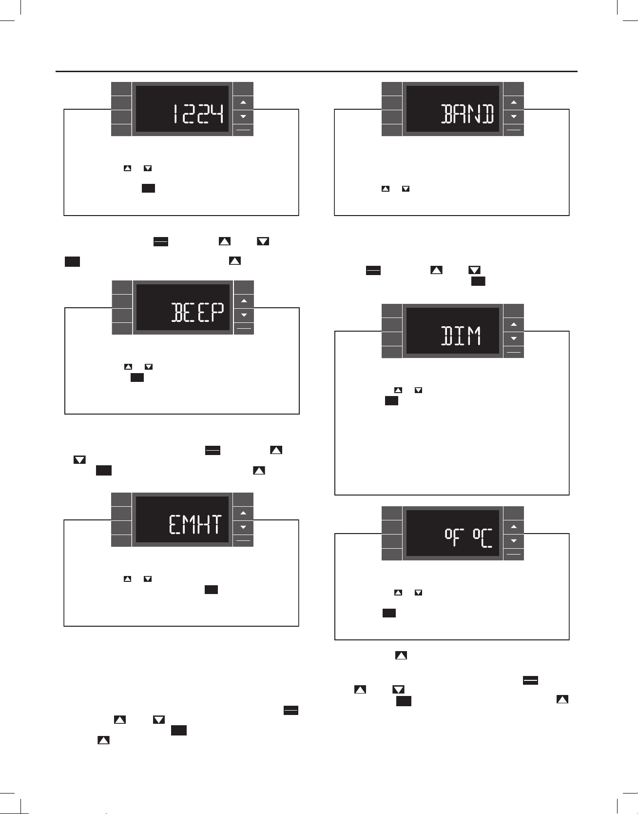
Time Setting – When in the User Menu, on the Control Panel, use the
(UP) and
fl ashes. Use the
DISPLAY
ENTER
. The minutes segment and AM or PM fl ashes. Use the (UP) and
(D OWN) to s elect TIM E. Pus h
(UP) and
(DOWN) to set the hour, then push
(DOWN) to set the minutes, then push
NOTE: If the AM or PM indicator is incorrect, push
segment fl ashes, use the
(UP) or
the hour segment 12 hours, then push
displays. Use the
day. Press the
(UP) or
BACK
key to go back to the TIME screen. Press
DISPLAY
, the hours segment
ENTER
DISPLAY
.
ENTER
DISPLAY
until the hours
ENTER
(DOWN) to advance
DISPLAY
. The day of the week
ENTER
(DOW N) to selec t the c urrent
(UP) to go to the next menu 1224.
NOTE: Pressing the
BACK
button again will exit the user menu function
mode. Or simply leave the control inactive for 15 seconds and
the control will return back to normal operation.
wwwwww.sylvane.com 1 (800) 934-9194
11
920-198-00
BACK
SYSTEM
FAN
MODE
FAN
SPEED
SCHEDULE
EXIT
DISPLAY
ENTER
User presses or to toggle the format between 12HR and
24HR display. To exit the selection process and accept the
change, press the key.
Clock Type – You may select between a 12 hr and 24 hr clock. When
1224 is displayed press the
BACK
DISPLAY
key then press (UP) or
ENTER
FRR063
(DOWN)
to toggle between 12 hr and 24 hr clock. To accept the change, press the
BACK
key to return to the 1224 screen. Press the (UP) to go to the
next menu BEEP.
BACK
SYSTEM
FAN
MODE
FAN
SPEED
SCHEDULE
User presses or to toggle between Beep On and Beep
Off. Press the key to accept the change and exit the
BACK
selection process.
EXIT
DISPLAY
ENTER
FRR064
BACK
SYSTEM
FAN
MODE
FAN
SPEED
SCHEDULE
EXIT
DISPLAY
ENTER
The menu allows the user to adjust the minimum spread
between the Auto Cool set point and the Auto Heat set point.
Press the or key to adjust. The adjust range is 3 to 10.
FRR066
Auto Changeover ‘Dead Band’ – For Kühl+ models with the auto
changeover feature you can select the temperature band between heating
and cooling. From the factory the band is set at 3° F (-16° C). The band is
adjustable from 3° F (-16° C) to 10° F (-12° C). When BAND is displayed
press the
3 and 10. To accept the change, press the
DISPLAY
key then press
ENTER
SYSTEM
FAN
MODE
FAN
SPEED
SCHEDULE
(UP) or
(DOWN) to toggle between
BACK
key to return to the BAND
BACK
EXIT
DISPLAY
ENTER
User presses or to select between AUTO, DM 20, OFF.
Press the key to accept the change and exit the
BACK
selection process.
Audible Alerts – You can select to have the control beep when buttons
are pushed at the unit control or when a signal is received from the remote
control. When BEEP is displayed press the
or
(DOWN) to toggle between ON and OFF. To accept the change,
press the
BACK
key to return to the BEEP screen. Press the (U P) to go
DISPLAY
key then press
ENTER
(UP)
to the next menu EMHT on Kühl+ models or F C for Kühl models.
BACK
SYSTEM
FAN
MODE
FAN
SPEED
SCHEDULE
EXIT
DISPLAY
ENTER
User presses or to toggle between Emergency Heat On
and Emergency Heat Off. Press the key to accept the
BACK
change and exit the selection process.
FRR065
Emergency Heat – The Kühl+ heat pump models (YS, YM, YL) have
a special feature that is designed to bring the temperature of the space
up quickly when the unit is fi rst cycled into the heating mode. With the
emergency heat feature enabled the electric heat will be used to bring the
temperature up to the setpoint initially, then utilize the energy saving heat
pump mode to maintain the temperature. If the emergency heat feature
is not selected the unit may take more time initially to reach the setpoint
at the initial selection of heat. When EMHT is displayed press the
key then press
(UP) or
To accept the change, press the
Press the
12
(UP) to go to the next menu BAND.
(DOWN) to toggle between ON and OFF.
BACK
key to return to the EMHT screen.
DISPLAY
ENTER
The Dim Auto automatically dims the display and then turns it
off after a period of time. The Dim 20 setting behavior is similar
to AUTO, but prevents the display from turning off. Minimum
brightness is 20%. The Dim Off setting forces the display to run
at full brightness.
FRR067
BACK
SYSTEM
FAN
MODE
FAN
SPEED
SCHEDULE
EXIT
DISPLAY
ENTER
User presses or at the same time to toggle between
Fahrenheit or Celsius as their temperature unit of choice.
Press the key to accept the change and exit the selection
BACK
process.
FRR068
screen. Press the
Fahrenheit / Celsius Selection – You may select between displaying
temperature in F or C. When F C is displayed press the
press
(UP) or (DOWN) to toggle bet ween F and C. To accept the
change, press the
(UP) to go to the next menu F C.
DISPLAY
ENTER
key to return to the F C screen. Press the
BACK
key then
wwwwww.sylvane.com 1 (800) 934-9194
SYSTEM
FAN
MODE
FAN
SPEED
SCHEDULE
920-198-00
BACK
EXIT
DISPLAY
ENTER
User presses or to select between Freeze Protection On
& Freeze Protection Off. Press the key to accept the
BACK
change and exit the selection process.
FRR069
(UP) to go to the next menu FRZ.
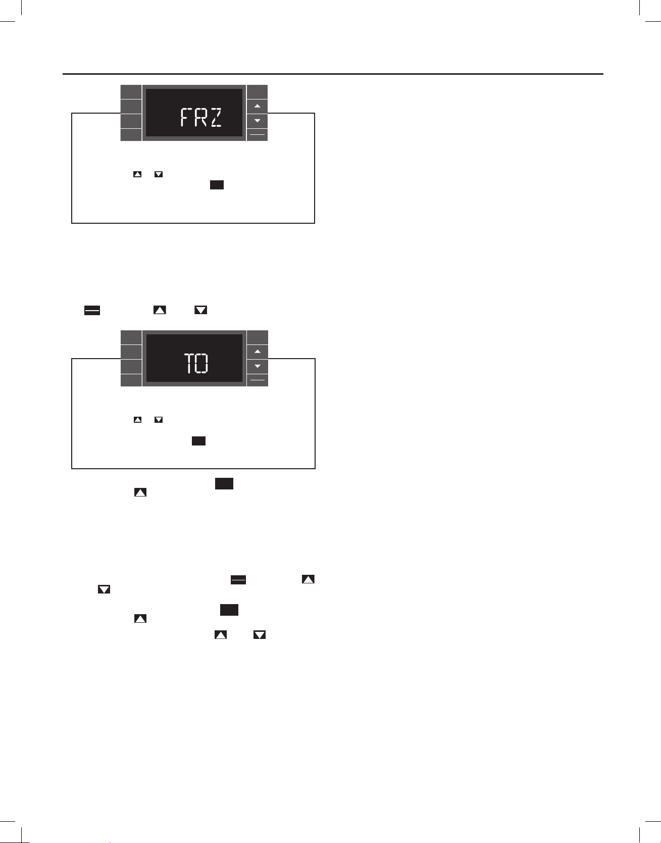
Freeze Protection – The Kühl+ models have a special feature that is
designed to keep the interior space above freezing by energizing the
electric heater anytime the indoor room temperature falls to 40° F (4° C).
With the freeze protection feature turned on, when the unit senses the
indoor temperature fall to 40° F (4° C) the unit will run the heater and high
fan until the space reaches 46° F (8° C) When FRZ is displayed press
DISPLAY
the
key then press (UP) or
ENTER
SYSTEM
FAN
MODE
FAN
SPEED
SCHEDULE
User presses or to increment/decrement the temperature
offset (TO) for the room temperature sensor. (Maximum offset
= +/- 8 degrees F). Press the key to accept the change
and exit the selection process
(DOWN) to toggle between ON
BACK
EXIT
DISPLAY
ENTER
BACK
FRR070
BACK
and OFF. To accept the change, press the
screen. Press the
(UP) to go to the next menu TO.
key to return to the FRZ
Temperature Offset – In some cases the built in thermostat on the unit
may not display the temperature as it is felt in the room. This can be caused
by many things including the size of the unit, the heat load on the room or
other factors. Friedrich allows you to select the appropriate temperature
offset to make the temperature readout as accurate as possible for your
application. In many cases the factory 0° F (-18° C) offset will provide
an accurate temperature readout. To change the offset follow these
instructions. When TO is displayed press the
(UP) or
(DOWN) to toggle between 0° F (-18° C) and 8° F (-13° C).
DISPLAY
key then press
ENTER
In most instances an offset from 0° F (-18° C) to 2° F (-17° C) is all that is
necessary. To accept the change, press the
screen. Press the
(UP) to go to the next menu TIME.
You may cycle through the menus using the
BACK
key to return to the TO
(UP) or (DO WN) k eys
wwwwww.sylvane.com 1 (800) 934-9194
13
920-198-00
to access any of the menus.
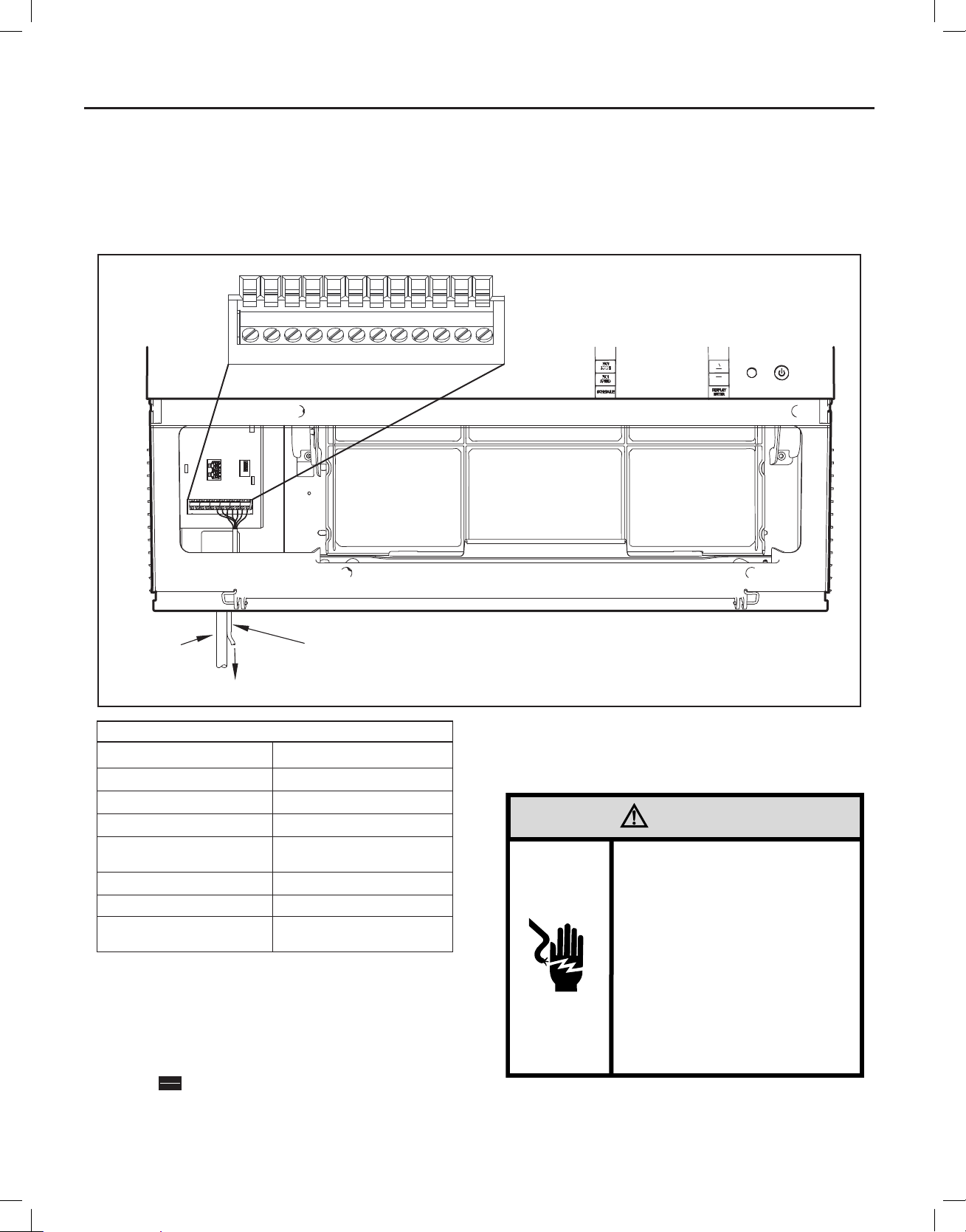
Add a Remote Thermostat
Remote Thermostat – An external thermostat may be added to the air
conditioner to provide remote temperature sensing and control. The
thermostat interface connector is located on the panel behind the front
grille. To enable the remote thermostat operation, remove the jumper
Figure 9
FP
THERMOSTAT CONNECTOR
F2
D2
F1
GH
CD1
GL
B
Y
4. Changing modes on the remote thermostat will not illuminate the
Control Panel LCD.
Remote Thermostat Selection
Friedrich recommends the use of either the RT4 or RT5. The RT4 is a
digital display thermostat with single speed fan control. The RT5 features
a digital display, two fan speed selection, battery backup and backlight.
W
R
POWER
CORD
TO REMOTE THERMOSTAT
Tab l e 2
Terminal Code Wire Connection Function
Interface Defi nitions
C Common Ground Terminal
GH Call for Heating
GL Call for Compressor
B
Y Call for low fan
W Call for high fan
R
THERMOSTAT WIRE ROUTING USE #18
AWG COLORED THERMOSTAT WIRE
24V Power from Electronic
Control to Wall Thermostat
Call for heat pump reversing
valve
between terminals 11 & 12 on the terminal block. Connect the thermostat
using Figure 9 and Table 2 as a guide.
If you connect an external thermostat, all Control Panel buttons will be
disabled with the following exception:
1. Maintenance commands (double button press & single button
extended press).
DISPLAY
2. The
ENTER
button for Freeze protection.
3. First Button pushed, illuminate the LCD.
FRR004
Other the rmostats may be used as l ong as they are confi g ured correctly fo r the unit.
For cooling models a sin gle stage cooling t hermostat with C, R, G , Y terminals must
be used. For ele ctric heat ‘E’ mode ls a single stage heating a nd cooling thermo stat
with C, R, G, Y, W terminals must be used. For heat pump ‘Y’ models a single
stage heating and cooling thermostat with C, R, G, Y, W, B terminals must be used.
CAUTION
It is the installer’s responsibility to
ensure that all control wiring
connections are made in accordance
with the installation instructions.
Improper connection of the thermostat
control wiring and/or tampering with
the unit’s internal wiring can void the
equipment warranty.
Failure to follow these instructions can
result in personal injury and damage to
product or other property.
14
wwwwww.sylvane.com 1 (800) 934-9194
 Loading...