


Friedrich Es12j33, El33j35, Es15j33a, Em18j34a, El24j35 Owner's Manual
...1997 TwinTemp® J Series
YS09J10
YS13J33
YM18J34A
YL24J35
ES12J33
ES15J33A
EM18J34A
EL24J35
EL33J35
EK12J33A
EK18J34A
Service & Parts
Manual
AMERICA’S BEST AIR CONDITIONER
TABLE OF CONTENTS |
|
|
PAGE |
GENERAL |
|
Friedrich Room Model Number Code ....................................................................................................... |
4 |
Application and Sizing .............................................................................................................................. |
5 |
Instructions For Using Cooling Load Estimate Form ................................................................................ |
6 |
Cooling Load Estimate Form .................................................................................................................... |
7 |
Heat Load Form ....................................................................................................................................... |
8 |
Heating Load Form Friedrich Unit Heat Pumps ....................................................................................... |
9 |
SPECIFICATIONS/PERFORMANCE DATA |
|
Specifications “YS” - "YM" - "YL" Models ....................................................................................... ......... |
10 |
Performance Data (Cooling) “YS” - "YM" - "YL" Models .......................................................................... |
11 |
Performance Data (Heating) “YS” - "YM" - "YL" Models .......................................................................... |
1 1 |
Specifications “ES” - "EM" - "EL" - "EK" Models ................................................................................ ..... |
12 |
Performance Data (Cooling & Heating) “ES” - "EM" - "EL" - "EK" Models............................................... |
13 |
REFRIGERANT REVERSE CYCLE |
|
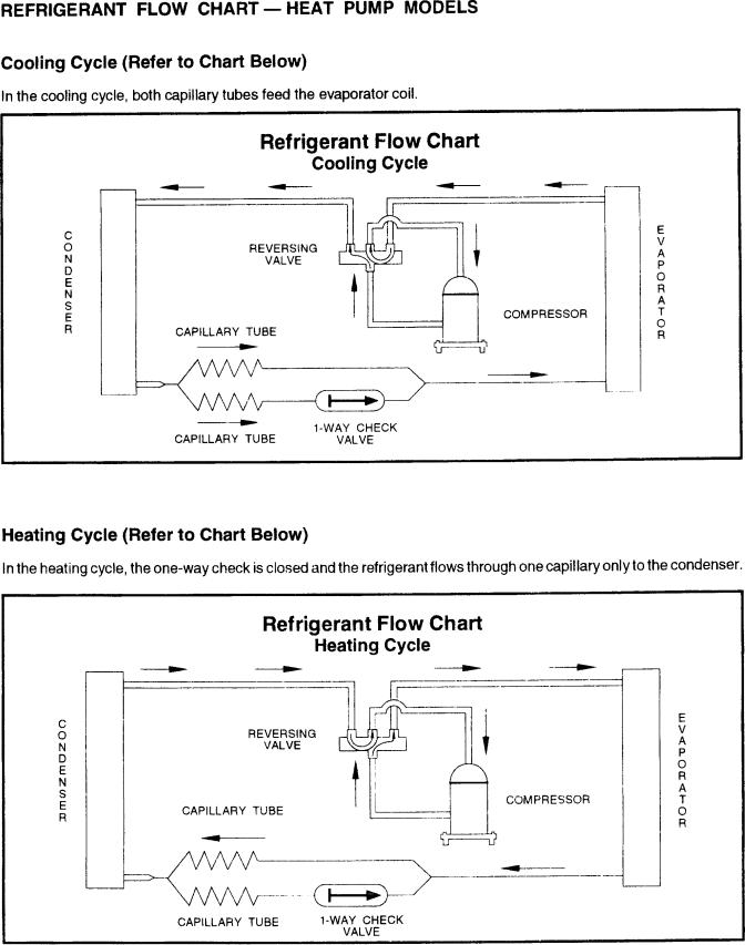
Refrigerant Flow Chart (Cooling Cycle) .................................................................................................. |
14 |
Refrigerant Flow Chart (Heating Cycle) .................................................................................................. |
14 |
INSTALLATION INSTRUCTIONS |
|
Installation Instructions for DC-2 Drain Kit .............................................................................................. |
15 |
COMPONENTS OPERATION/TESTING |
|
Compressors ........................................................................................................................................... |
16 |
Thermal Overload (External) ................................................................................................................... |
16 |
Thermal Overload (Internal) .................................................................................................................... |
17 |
Fan Motor ................................................................................................................................................ |
17 |
Capacitor, Run ........................................................................................................................................ |
18 |
System Control Switch (Heat Pump & Electric Heat Models) ................................................................. |
18 |
Thermostat .............................................................................................................................................. |
19 |
Thermostat (“YQ” Model) ........................................................................................................................ |
18 |
Thermostat Adjustment .......................................................................................................................... |
20 |
Resistor (Heat Anticipator) ...................................................................................................................... |
20 |
MoneySaver Switch................................................................................................................................. |
20 |
Heat Element .......................................................................................................................................... |
21 |
Defrost Thermostat (Heat Pump Models) ............................................................................................... |
21 |
Defrost Bulb Location (Heat Pump Models) ............................................................................................ |
22 |
Solenoid Coil (Heat Pump Models Only) ................................................................................................. |
22 |
Check Valve ............................................................................................................................................. |
22 |
Drain Pan Valve ....................................................................................................................................... |
22 |
Reversing Valve (Heat Pump Models Only)............................................................................................. |
23 |
(Page 2 of 64) |
TTJ-0197 (1/97) |
TABLE OF CONTENTS (Cont.)
|
Page |
Sealed Refrigeration System Repairs ..................................................................................................... |
24 |
Hermetic Component Replacement ........................................................................................................ |
24 |
Special Procedure in the Case of Motor Compressor Burn-Out ............................................................. |
25 |
Rotary Compressor Special Troubleshooting & Service .......................................................................... |
25 |
Refrigerant Charge.................................................................................................................................. |
25 |
TROUBLESHOOTING
Troubleshooting Touch Test Chart ........................................................................................................... |
26 |
Troubleshooting Cooling .......................................................................................................................... |
27 |
Troubleshooting Heating (Heat Pump Models) ........................................................................................ |
31 |
Troubleshooting Heating (Cooling/Electric Models) ................................................................................. |
34 |
WIRING DIAGRAMS
YS09J10 ............................................................ |
618-200-04 .................................................................. |
36 |
YS13J33 ............................................................ |
618-200-02 .................................................................. |
37 |
YM18J34A ......................................................... |
618-200-02 .................................................................. |
37 |
YL24J35 ............................................................. |
618-200-02 .................................................................. |
37 |
ES12J33 ............................................................ |
618-200-01 .................................................................. |
38 |
ES15J33A .......................................................... |
618-200-01 .................................................................. |
38 |
EM18J34A ......................................................... |
618-200-01 .................................................................. |
38 |
EL24J35 ............................................................. |
618-200-01 .................................................................. |
38 |
EL33J35 ............................................................. |
618-200-01 .................................................................. |
38 |
EK12J33A .......................................................... |
618-200-01 .................................................................. |
38 |
EK18J34A .......................................................... |
618-200-01 .................................................................. |
38 |
PARTS LIST
"YS" - "YM" - "YL” Series Parts List ......................................................................................................... |
39 |
“ES" - "EM” Series Parts List .................................................................................................................. |
46 |
“EL” Series Parts List............................................................................................................................... |
51 |
“EK” Series Parts List ......................................................................................................... ..................... |
56 |
TTJ-0197 (1/97) |
(Page 3 of 64) |
FRIEDRICH ROOM MODEL NUMBER CODE
E S 15 H 3 3 A
1st DIGIT - FUNCTION
S = Straight Cool, Value Series
C = Straight Cool, Budget Series Y = Heat Pump
E = Electric Strip
K = Straight Cool, Challenger Series W = Thru-The-Wall, WallMaster Series
2nd DIGIT - TYPE
C = Casement
P = PowerMiser “Portable” Q = QStar
S = Small Chassis M = Medium Chassis L = Large Chassis W = Built-In
H = Hazardgard
3rd & 4th DIGITS - APPROXIMATE BTU/HR (Cooling)
Heating BTU/HR capacity listed in Specifications/Performance Data Section
5th DIGIT - ALPHABETICAL MODIFIER
6th DIGIT - VOLTAGE
1 = 115 Volts
2 = 230 Volts
3 = 230-208 Volts
7th DIGIT
0 = Straight Cool & Heat Pump Models ELECTRIC HEAT MODELS
1 = 1 KW Heat Strip, Nominal
3 = 3 KW Heat Strip, Nominal
4 = 4 KW Heat Strip, Nominal
5 = 5 KW Heat Strip, Nominal
8 = 8 KW Heat Strip, Nominal
8th DIGIT
Major Change
(Page 4 of 64) |
TTJ-0197 (1/97) |
APPLICATION AND SIZING
In the application and sizing of room air conditioners for cooling, it is most important to give full consideration to all factors which may contribute to the heat loss or gain of the space to be conditioned. It is therefore necessary to make a survey of the space to be conditioned and calculate the load requirements before a selection of the size of the equipment needed can be made.
The load requirement may be determined very easily by simply using the standard “AHAM” Load Calculating Form, on Page 7. This form is very easy to use and is self explanatory throughout. It is necessary only to insert the proper measurements on the lines provided and multiply by the given factors, then add the result for the total load requirements.
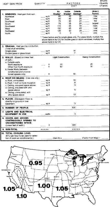
Cooling load requirements are generally based on the cooling load for comfortable air conditioning which does not require specific conditions of inside temperature and humidity. The load calculation form is based on outside design temperature of 95° FDB and 75° FWB. It can be used for areas in the Continental United States having other outside design temperatures by applying a correction factor for the particular locality as determined from the map shown on Page 6.
When sizing a TwinTemp unit for cooling and heating, we must remember that the heating capacity of any given unit varies directly with the outdoor ambient temperature. Also, we must keep in mind the average low temperatures which might be experienced in the locality where the unit is to be installed. Therefore, when sizing a TwinTemp unit, both cooling and heating requirements must be calculated. Do not oversize, or undersize, one phase of the unit’s capacity at the expense of the other. In those cases where the unit will provide satisfactory cooling at all times but will be inadequate for those few times that the outdoor temperature is below the maximum low for the unit, additional auxiliary heating facilities must be provided to insure that adequate heat is available at all times.
TTJ-0197 (1/97) |
(Page 5 of 64) |
INSTRUCTIONS FOR USING COOLING LOAD ESTIMATE
FORM FOR ROOM AIR CONDITIONERS
(AHAM PUB. NO. RAC-1)
A.This cooling load estimate form is suitable for estimating the cooling load for comfort air conditioning installations which do not require specific conditions of inside temperature and humidity.
B.The form is based on an outside design temperature of 95°F dry bulb and 75°F wet bulb. It can be used for areas in the continental United States having other outside design temperatures by applying a correction factor for the particular locality as determined from the map.
C.The form includes “day” factors for calculating cooling loads in rooms where daytime comfort is desired (such as living rooms, offices, etc.)
D.The numbers of the following paragraphs refer to the corresponding numbered item on the form:
1.Multiply the square feet of window area for each exposure by the applicable factor. The window area is the area of the wall opening in which the window is installed. For windows shaded by inside shades or venetian blinds, use the factor for “Inside Shades.” For windows shaded by outside awnings or by both outside awnings and inside shades (or venetian blinds), use the factor for “Outside Awnings.” “Single Glass” includes all types of single thickness windows, and “Double Glass” includes sealed airspace types, storm windows, and glass block. Only one number should be entered in the right hand column for Item 1, and this number should represent only the exposure with the largest load.
2.Multiply the total square feet of all windows in the room by the applicable factor.
3a. Multiply the total length (linear feet) of all walls exposed to the outside by the applicable factor. Doors should be considered as being part of the wall. Outside walls facing due north should be calculated separately from outside walls facing other directions. Walls which are permanently shaded by adjacent structures should be considered “North Exposure.” Do not consider trees and shrubbery as providing permanent shading. An un-insulated frame wall or a masonry wall 8 inches or less in thickness is considered “Light Construction.” An insulated wall or masonry wall over 8 inches in thickness is considered “Heavy Construction.”
3b. Multiply the total length (linear feet) of all inside walls between the space to be conditioned and any unconditioned spaces by the given factor. Do not include inside walls which separate other air conditioned rooms.
4.Multiply the total square feet of roof or ceiling area by the factor given for the type of construction most nearly describing the particular application (use one line only.)
5.Multiply the total square feet of floor area by the factor given. Disregard this item if the floor is directly on the ground or over a basement.
6.Multiply the number of people who normally occupy the space to be air conditioned by the factor given. Use a minimum of 2 people.
7.Determine the total number of watts for light and electrical equipment, except the air conditioner itself, that will be in use when the room air conditioning is operating. Multiply the total wattage by the factor given.
8.Multiply the total width (linear feet) of any doors or arches which are continually open to an unconditioned space by the applicable factor.
NOTE: Where the width of the doors or arches is more than 5 feet, the actual load may exceed the calculated value. In such cases, both adjoining rooms should be considered as a single large room, and the room air conditioner unit or units should be selected according to a calculation made on this new basis.
9.Total the loads estimated for the foregoing 8 items.
10.Multiply the subtotal obtained in item 9 by the proper correction factor, selected from the map, for the particular locality. The result is the total estimated design cooling load in BTU per hour.
E.For best results, a room air conditioner unit or units having a cooling capacity rating (determined in accordance with the NEMA Standards Publication for Room Air Conditioners, CN 1-1960) as close as possible to the estimated load should be selected. In general, a greatly oversized unit which would operate intermittently will be much less satisfactory than one which is slightly undersized and which would operate more nearly continuously.
F.Intermittent loads such as kitchen and laundry equipment are not included in this form.
(Page 6 of 64) |
TTJ-0197 (1/97) |
COOLING LOAD ESTIMATE FORM
TTJ-0197 (1/97) |
(Page 7 of 64) |
HEAT LOAD FORM
The heat load form, Page 9, may be used by servicing personnel to determine the heat loss of a conditioned space and the ambient winter design temperatures in which the unit will heat the calculated space.
The upper half of the form is for computing the heat loss of the space to be conditioned. It is necessary only to insert the proper measurements on the lines provided and multiply by the given factors, then add this result for the total heat loss in BTU/Hr./°F.
The BTU/Hr. per °F temperature difference is the 70°F inside winter designed temperature minus the lowest outdoor ambient winter temperature of the area where the unit is installed.This temperature difference is used as the multiplier when calculating the heat loss.
The graph shows the following:
Left Hand Scale |
Unit capacity BTU/Hr. or heat |
|
loss BTU/Hr. |
Bottom Scale |
Outdoor ambient temperature, |
|
base point. |
Heat Pump Model |
BTU/Hr. capacity heat pump will |
|
deliver at outdoor temperatures. |
Balance Point |
Maximum BTU/Hr. heat pump |
|
will deliver at indicated ambient |
|
temperature. |
Below is an example using the heat load form:
A space to be conditioned is part of a house geographically located in an area where the lowest outdoor ambient winter temperature is 40°F.The calculated heat loss is 184 BTU/Hr./°F.
Subtract 40°F (lowest outdoor ambient temperature for the geographical location) from 70°F (inside design temperature of the unit) for a difference of 30°F. Multiply 184 by 30 for a 5500 BTU/Hr. total heat loss for the calculated space.
On the graph, plot the base point (70°) and a point on the 40°F line where it intersects with the 5500 BTU/Hr. line on the left scale. Draw a straight line from the base point 70 through the point plotted at 40°F. This is the total heat loss line.
Knowing that we have a 5500 BTU/Hr. heat loss, and we expect that our heat pump will maintain a 70°F inside temperature at 40°F outdoor ambient, we plot the selected unit capacity BTU/Hr. of the unit between 35° and 60° on the graph and draw a straight line between these points. Where the total heat loss line and the unit capacity line intersect, read down to the outdoor ambient temperature scale and find that this unit will deliver the required BTU/Hr. capacity to approximately 30°F.
(Page 8 of 64) |
TTJ-0197 (1/97) |

TTJ-0197 (1/97) |
(Page 9 of 64) |
SPECIFICATIONS |
YS09J10 |
YS13J33 |
YM18J34A |
YL24J35 |
||
BTUH (Cooling) |
|
9000 |
13000 |
17500 |
24000 |
|
|
|
|
|
13000 |
17500 |
23800 |
BTUH (Heating) |
|
8300 |
12400 |
16500 |
23000 |
|
|
|
|
|
12300 |
16300 |
22800 |
E.E.R. (Cooling) |
|
11.5 |
9.8 |
9.4 |
9.0 |
|
|
|
|
|
9.8 |
9.4 |
9.0 |
E.E.R. (Heating) |
|
11.0 |
9.4 |
9.6 |
9.8 |
|
|
|
|
|
9.4 |
9.6 |
9.8 |
Volts |
|
115 |
230 |
230 |
230 |
|
|
|
|
|
208 |
208 |
208 |
Amperes (Cooling) |
|
7.2 |
6.0 |
8.3 |
12.0 |
|
|
|
|
|
6.5 |
9.1 |
13.0 |
Amperes (Heating) |
|
6.7 |
6.0 |
7.6 |
10.4 |
|
|
|
|
|
6.5 |
8.3 |
11.5 |
Total Watts (Cooling) |
|
780 |
1325 |
1860 |
2665 |
|
|
|
|
|
1325 |
1860 |
2645 |
|
|
|
|
|
|
|
Hertz |
|
60 |
60 |
60 |
60 |
|
|
|
|
|
|
|
|
Fuse/Breaker Size |
|
15 |
20 |
30 |
30 |
|
|
|
|
|
|
|
|
|
|
Amps |
|
16.0 |
19.5 |
24.0 |
Resistance |
|
|
|
14.7 |
17.0 |
22.4 |
|
Watts |
|
3500 |
4200 |
5500 |
|
Heater |
|
|
|
2900 |
3500 |
4650 |
|
|
BTUH |
|
10700 |
13000 |
17300 |
|
|
|
|
8900 |
10600 |
14300 |
Fan RPM |
|
1110 |
1110 |
1120 |
1120 |
|
|
|
|
|
|
|
|
Evaporator Air CFM |
|
300 |
325 |
425 |
600 |
|
|
|
|
|
|
|
|
Exhaust Air CFM |
|
Yes |
Yes |
Yes |
Yes |
|
|
|
|
|
|
|
|
Dehumidification Pts/Hr |
1.7 |
3.5 |
5.2 |
7.0 |
||
|
|
|
|
|
|
|
Width |
|
2515/16" |
2515/16" |
2515/16" |
28" |
|
|
|
|
|
|
|
|
Height |
|
1515/16" |
1515/16" |
1715/16" |
203/16" |
|
|
|
|
|
|
|
|
Depth |
|
273/8" |
273/8" |
273/8" |
335/8" |
|
|
|
|
|
|
||
Minimum Ext. Into Room |
31/16" |
31/16" |
31/16" |
33/16" |
||
|
|
|
|
|
||
Minimum Ext. to Outside |
1615/16" |
1615/16" |
1615/16" |
1815/16" |
||
|
|
|
|
|
|
|
Net Weight |
|
113 |
117 |
141 |
198 |
|
|
|
|
|
|
|
|
Shipping Weight |
|
124 |
128 |
153 |
217 |
|
|
|
|
|
|
|
|
(Page 10 of 64) |
TTJ-0197 (1/97) |
PERFORMANCE |
EVAPORATOR AIR |
OPERATING |
ELECTRICAL |
R-22 |
COMP. |
||||
DATA* |
|
TEMP. °F. |
PRESSURES |
RATINGS |
REFRIG. |
OIL |
|||
Cooling |
|
|
|
|
|
|
|
|
|
|
DISCHARGE |
TEMP. |
SUCTION |
DISCHARGE |
AMPS |
LOCKED |
CHARGE IN |
CHARGE IN |
|
|
|
AIR |
DROP °F |
|
|
|
ROTOR AMPS |
OZ. |
FLUID OZ. |
|
|
|
|
|
|
|
|
|
|
YS09J10 |
|
59.0 |
21.0 |
87.0 |
241 |
7.2 |
39.2 |
28.0 |
11.8 |
|
|
|
|
|
|
|
|
|
|
YS13J33 |
|
56.0 |
24.0 |
75.0 |
280 |
6.0 |
29.0 |
30.0 |
11.8 |
|
|
|
|
|
|
6.5 |
|
|
|
YM18J34 |
|
53.0 |
27.0 |
74.0 |
277 |
8.7 |
42.0 |
54.0 |
30.0 |
|
|
|
|
|
|
9.3 |
|
|
|
YL24J35 |
|
55.0 |
25.0 |
77.0 |
272 |
12.0 |
61.0 |
69.0 |
32.0 |
|
|
|
|
|
|
13.0 |
|
|
|
* Rating Conditions: |
80°F Room Air Temperature and 50% Relative Humidity with |
|
|
|
|
||||
|
95°F Outside Air Temperature at 40% Relative Humidity. |
|
|
|
|
||||
PERFORMANCE DATA |
*YS09J10 |
**YS13J33 |
**YM18J34 |
**YL24J35 |
|
(Heating) |
|
|
|
|
|
|
|
|
|
|
|
AHAM @ 70°F Inside 47°F Outside |
8300 |
12400/12300 |
17200/17200 |
23000/22800 |
|
|
@ 70°F Inside 35°F Outside |
|
10700/8900 |
13000/10600 |
17300/14300 |
|
|
|
|
|
|
Evaporator Air Temperature Rise |
|
|
|
|
|
|
@ 70°F Inside 47°F Outside |
19.62 |
31.38 |
24.74 |
31.71 |
|
@ 70°F Inside 35°F Outside |
|
28.69/23.87 |
24.46/20.22 |
24.38/20.16 |
|
|
|
|
|
|
AMPS @ 70°F Inside 47°F Outside |
6.7 |
6.0/6.5 |
8.5/9.0 |
10.4/11.5 |
|
|
@ 70°F Inside 35°F Outside |
|
16.0/14.7 |
19.5/17.0 |
24.0/22.4 |
|
|
|
|
|
|
Watts |
@ 70°F Inside 47°F Outside |
760 |
1340/1300 |
1880/1820 |
2350/2340 |
|
@ 70°F Inside 35°F Outside |
|
3500/2900 |
5500/4650 |
5500/4650 |
|
|
|
|
|
|
Suction/Head PSIG |
|
|
|
|
|
|
@ 70°F Inside 47°F Outside |
53.5/222 |
52.5/251 |
53/225 |
54/236.5 |
|
|
|
|
|
|
*Do not operate below 37° ambient.
**Heating element comes on at 35°F outside ambient and compressor shuts off.
TTJ-0197 (1/97) |
(Page 11 of 64) |
SPECIFICATIONS |
ES12J33 |
ES15J33A |
EM18J34 |
EL24J35 |
EL33J35 EK12J33A EK18J34A |
||
BTUH (Cooling) |
12000 |
15000 |
18500 |
24000 |
33000 |
12500 |
18000 |
|
12000 |
15000 |
18300 |
24000 |
32500 |
12500 |
18000 |
BTUH (Heating) |
10700 |
10700 |
13000 |
17300 |
17300 |
10700 |
13000 |
|
8900 |
8900 |
10600 |
14300 |
14300 |
8900 |
10600 |
E.E.R. (Cooling) |
10.5 |
9.6 |
10.0 |
9.2 |
9.0 |
9.6 |
9.6 |
|
11.0 |
9.6 |
10.0 |
9.1 |
9.0 |
9.6 |
9.6 |
E.E.R. (Heating) |
|
|
|
|
|
|
|
|
|
|
|
|
|
|
|
Volts |
230 |
230 |
230 |
230 |
230 |
230 |
230 |
|
208 |
208 |
208 |
208 |
208 |
208 |
208 |
Amperes (Cooling) |
5.5 |
6.9 |
8.4 |
12.0 |
17.0 |
5.8 |
8.3 |
|
5.7 |
7.5 |
9.0 |
13.3 |
18.0 |
6.2 |
9.1 |
Amperes (Heating) |
16.0 |
16.0 |
19.5 |
24.0 |
24.0 |
16.0 |
19.5 |
|
14.7 |
14.7 |
17.0 |
22.4 |
22.4 |
14.7 |
17.0 |
Total Watts (Cooling) |
1140 |
1665 |
1850 |
2610 |
3670 |
1250 |
1875 |
|
1090 |
1655 |
1830 |
2640 |
3610 |
1250 |
1875 |
Hertz |
60 |
60 |
60 |
60 |
60 |
60 |
60 |
|
|
|
|
|
|
|
|
Fuse/Breaker Size |
20 |
20 |
30 |
30 |
30 |
20 |
30 |
|
|
|
|
|
|
|
|
Fan RPM |
1120 |
1100 |
1120 |
1100 |
1100 |
1080 |
1120 |
|
|
|
|
|
|
|
|
Evaporator Air CFM |
325 |
325 |
425 |
560 |
700 |
325 |
440 |
|
|
|
|
|
|
|
|
Fresh Air CFM |
Yes |
Yes |
Yes |
Yes |
Yes |
Yes |
Yes |
|
|
|
|
|
|
|
|
Exhaust Air CFM |
Yes |
Yes |
Yes |
Yes |
Yes |
Yes |
Yes |
|
|
|
|
|
|
|
|
Dehumidification Pts/Hr |
3.5 |
5.0 |
5.7 |
7.7 |
11.0 |
3.5 |
5.5 |
|
|
|
|
|
|
|
|
Width |
2515/16" |
2515/16" |
2515/16" |
28" |
28" |
2515/16" |
2515/16" |
|
|
|
|
|
|
|
|
Height |
1515/16" |
1515/16" |
1715/16" |
203/16" |
203/16" |
1515/16" |
1715/16" |
|
|
|
|
|
|
|
|
Depth |
273/8" |
273/8" |
273/8" |
335/8" |
335/8" |
273/8" |
273/8" |
|
|
|
|
|
|
|
|
Minimum Ext. Into Room |
31/16" |
31/16" |
31/16" |
33/16" |
33/16" |
31/16" |
31/16" |
|
|
|
|
|
|
|
|
Minimum Ext. to Outside |
1615/16" |
1615/16" |
1615/16" |
1815/16" |
1815/16" |
1615/16" |
1615/16" |
|
|
|
|
|
|
|
|
Net Weight |
110 |
121 |
135 |
191 |
215 |
108 |
133 |
|
|
|
|
|
|
|
|
Shipping Weight |
121 |
132 |
147 |
210 |
234 |
119 |
145 |
|
|
|
|
|
|
|
|
(Page 12 of 64) |
TTJ-0197 (1/97) |
PERFORMANCE |
EVAPORATOR AIR |
OPERATING |
ELECTRICAL |
R-22 |
COMP. |
||||
DATA* |
|
TEMP. °F. |
PRESSURES |
RATINGS |
REFRIG. |
OIL |
|||
Cooling |
|
|
|
|
|
|
|
|
|
|
DISCHARGE |
TEMP. |
SUCTION |
DISCHARGE |
AMPS |
LOCKED |
CHARGE IN |
CHARGE IN |
|
|
|
AIR |
DROP °F |
|
|
|
ROTOR AMPS |
OZ. |
FLUID OZ. |
|
|
|
|
|
|
|
|
|
|
ES12J33 |
|
58.0 |
22.0 |
77.5 |
266 |
5.5 |
26.3 |
26.0 |
11.8 |
|
|
|
|
|
|
5.7 |
|
|
|
ES15J33A |
|
53.0 |
27.0 |
77.0 |
260 |
7.4 |
42.0 |
49.0 |
30.0 |
|
|
|
|
|
|
8.2 |
|
|
|
EM18J34A |
|
55.0 |
25.0 |
73.0 |
262 |
8.2 |
42.0 |
49.0 |
30.0 |
|
|
|
|
|
|
8.7 |
|
|
|
EL24J35 |
|
55.0 |
25.0 |
73.5 |
280 |
12.0 |
61.0 |
53.0 |
32.0 |
|
|
|
|
|
|
13.3 |
|
|
|
EL33J35 |
|
52.0 |
28.0 |
71.0 |
299 |
17.0 |
94.0 |
81.0 |
35.0 |
|
|
|
|
|
|
18.0 |
|
|
|
EK12J33A |
|
57.0 |
23.0 |
79.0 |
293 |
5.8 |
26.3 |
26.0 |
11.8 |
|
|
|
|
|
|
6.2 |
|
|
|
EK18J33A |
|
55.0 |
25.0 |
73.0 |
262 |
8.2 |
42.0 |
46.0 |
30.0 |
|
|
|
|
|
|
8.8 |
|
|
|
* Rating Conditions: |
80°F Room Air Temperature and 50% Relative Humidity with |
|
|
|
|
||||
|
95°F Outside Air Temperature at 40% Relative Humidity. |
|
|
|
|
||||
PERFORMANCE DATA |
VOLTS |
BTUH |
CFM |
HEAT RISE |
Heating |
|
|
HIGH SPEED |
|
|
|
|
|
|
ES12J33 |
230 |
10700 |
1120 |
30.5 |
|
208 |
8900 |
|
|
ES15J33A |
230 |
10700 |
1100 |
30.5 |
|
208 |
8900 |
|
|
EM18J34A |
230 |
13000 |
1120 |
28.3 |
|
208 |
10600 |
|
|
EL24J35 |
230 |
17300 |
1100 |
28.6 |
|
208 |
14300 |
|
|
EL33J35 |
230 |
17300 |
1110 |
22.8 |
|
208 |
14300 |
|
|
EK12J33A |
230 |
10700 |
1080 |
30.5 |
|
208 |
8900 |
|
|
EK18J34A |
230 |
13000 |
1120 |
27.5 |
|
208 |
10600 |
|
|
TTJ-0197 (1/97) |
(Page 13 of 64) |
(Page 14 of 64) |
TTJ-0197 (1/97) |
INSTALLATION INSTRUCTIONS
FOR DC-2 DRAIN KIT
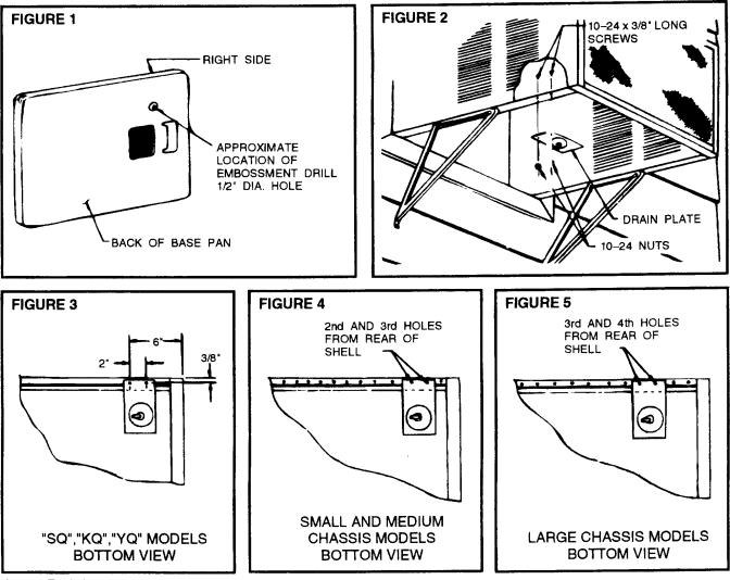
STEP 1 Before sliding chassis into outer shell, turn chassis on its side and add drain hole by drilling ½" diameter hole as shown in Figure 1.
STEP 2 DC-2 mounts to the bottom of the outer shell as shown in Figure 2 on the right side as you face the unit. Use two (2) 10 - 24 x 3/8" long machine screws and 10 - 24 hex nuts provided.
STEP 3 SQ, KQ, YQ Models - Drill two ¼" holes in outer shell as shown in Figure 3. Also drill a 3/8" diameter hole in the base pan 3½" from the back and 3½" from right side.
STEP 4 Small and Medium Chassis Models - Mount in second and third holes from the rear of shell; See Figure 4.
STEP 5 Large Chassis Models - Mount in third and fourth holes from the rear of shell; see Figure 5.
STEP 6 Connect a suitable length of garden hose or other tubing to end of the drain tube to drain the condensate away.
TTJ-0197 (1/97) |
(Page 15 of 64) |
COMPONENTS OPERATION & TESTING
WARNING
DISCONNECT ELECTRICAL POWER TO UNIT BEFORE SERVICING OR TESTING
COMPRESSORS
Compressors are single phase, 115 or 230/208 volt, depending on the model unit. All compressor motors are permanent split capacitor type using only a running capacitor across the start and run terminal.
All compressors are internally spring mounted and externally mounted on rubber isolators.
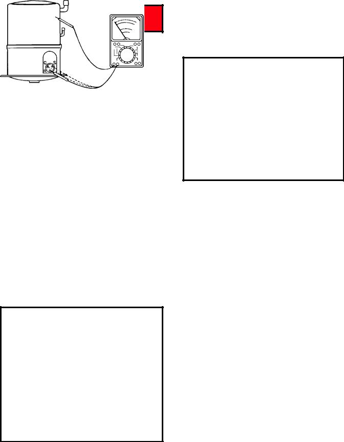
COMPRESSOR WINDING TEST (See Figure 1)
Remove compressor terminal box cover and disconnect wires from terminals. Using an ohmmeter, check continuity across the following:
1.Terminal “C” and “S” - no continuity - open winding - replace compressor.
2.Terminal “C” and “R” - no continuity - open winding - replace compressor.
3.Terminal “R” and “S” - no continuity - open winding - replace compressor.
Figure 1: Compressor Winding Test
GROUND TEST
Use an ohmmeter set on its highest scale. Touch one lead to the compressor body (clean point of contact as a good connection is a must) and the other probe in turn to each compressor terminal (see Figure 2.) If a reading is obtained, the compressor is grounded and must be replaced.
Figure 2: Typical Ground Test
CHECKING COMPRESSOR EFFICIENCY
The reason for compressor inefficiency is normally due to broken or damaged suction and/or discharge valves, reducing the ability of the compressor to pump refrigerant gas.
This condition can be checked as follows:
1.Install a piercing valve on the suction and discharge or liquid process tube.
2.Attach gauges to the high and low sides of the system.
3.Start the system and run a “cooling or heating performance test.”
If test shows:
A.Below normal high side pressure.
B.Above normal low side pressure.
C.Low temperature difference across coil.
The compressor valves are faulty - replace the compressor.
THERMAL OVERLOAD (External)
Some compressors are equipped with an external overload which is located in the compressor terminal box adjacent to the compressor body (see Figure 3.)
(Page 16 of 64) |
TTJ-0197 (1/97) |
The overload is wired in series with the common motor terminal. The overload senses both major amperage and compressor temperature. High motor temperature or amperage heats the disc causing it to open and break the circuit to the common motor terminal.
Should the internal temperature and/or current draw become excessive, the contacts in the overload will open, turning off the compressor. The overload will automatically reset, but may require several hours before the heat is dissipated.
Figure 3: External Overload
Heat generated within the compressor shell is usually due to:
1.High amperage.
2.Low refrigerant charge.
3.Frequent recycling.
4.Dirty condenser.
TERMINAL OVERLOAD - TEST
(Compressor - External Type)
1.Remove overload.
2.Allow time for overload to reset before attempting to test.
3.Apply ohmmeter probes to terminals on overload wires. There should be continuity through the overload.
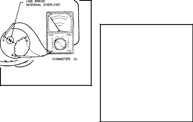
TERMINAL OVERLOAD (Internal)
Some model compressors are equipped with an internal overload. The overload is embedded in the motor windings to sense the winding temperature and/or current draw. The overload is connected in series with the common motor terminal.
CHECKING THE INTERNAL OVERLOAD
(see Figure 4.)
Figure 4 INTERNAL OVERLOAD
1.With no power to unit, remove the leads from the compressor terminals.
2.Using an ohmmeter, test continuity between terminals C-S and C-R. If not continuous, the compressor overload is open and the compressor must be replaced.
FAN MOTOR
A single phase permanent split capacitor motor is used to drive the evaporator blower and condenser fan. A self-resetting overload is located inside the motor to protect against high temperature and high amperage conditions.
FAN MOTOR - TEST
1.Determine that capacitor is serviceable.
2.Disconnect fan motor wires from fan speed switch or system switch.
3.Apply “live” test cord probes on black wire and common terminal of capacitor. Motor should run at high speed.
TTJ-0197 (1/97) |
(Page 17 of 64) |
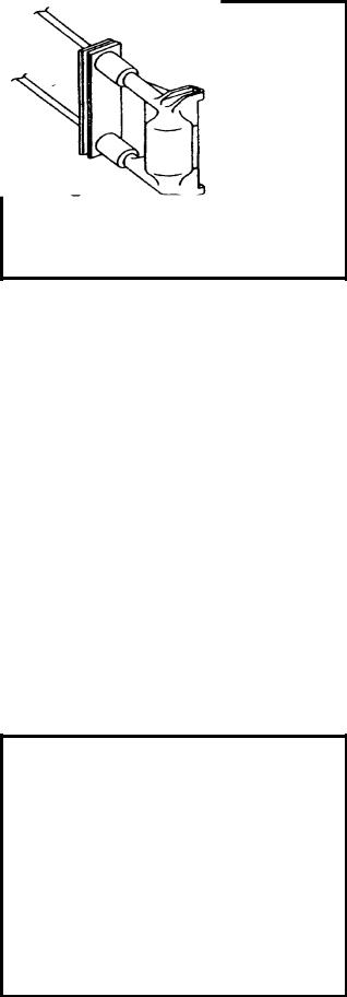
Figure 5: Fan Motor
4.Apply “live” test cord probes on red wire and common terminal of capacitor. Motor should run at low speed.
5.Apply “live” test cord probes on each of the remaining wires from the speed switch or system switch to test intermediate speeds.
CAPACITOR, RUN
A run capacitor is wired across the auxiliary and main winding of a single phase permanent split capacitor motor such as the compressor and fan motor. A single capacitor can be used for each motor or a dual rated capacitor can be used for both.
The capacitor's primary function is to reduce the line current while greatly improving the torque characteristics of a motor. The capacitor also reduces the line current to the motor by improving the power factor of the load.The line side of the capacitor is marked with a red dot and is wired to the line side of the circuit (see Figure 6.)
Figure 6: RUN CAPACITOR HOOK-UP
CAPACITOR - TEST
1.Remove capacitor from unit.
2.Check for visual damage such as bulges, cracks, or leaks.
3.For dual rated, apply an ohmmeter lead to common (C) terminal and the other probe to the compressor (HERM) terminal. A satisfactory capacitor will cause a deflection on the pointer, then gradually move back to infinity.
4.Reverse the leads of the probe and momentarily touch the capacitor terminals. The deflection of the pointer should be two times that of the first check if the capacitor is good.
5.Repeat steps 3 and 4 to check fan motor capacitor.
NOTE: A shorted capacitor will indicate a low resistance and the pointer will move to the "0" end of the scale and remain there as long as the probes are connected.
An open capacitor will show no movement of the pointer when placed across the terminals of the capacitor.
SYSTEM CONTROL SWITCH
(Heat Pump & Electric Heat Models)
An eight position control switch is used to regulate the operation of the fan motor and compressor. The compressor can be operated with the fan operating at low, medium or high speed in the cooling or heating mode. The fan motor can also be operated independently on medium speed. See switch section as indicated on decorative control panel (see Figure 7.)
1."Off" Position - everything is off.
2."Lo Cool" Position - fan operates on low speed, compressor is on.
3."Med Cool" Position - fan operates on medium speed, compressor is on.
4."Hi Cool" Position - fan operates on high speed, compressor is on.
5."Hi Heat" Position - fan operates on high speed, compressor or electric heater is on.
6."Med Heat" Position - fan operates on medium speed, compressor or electric heater is on.
(Page 18 of 64) |
TTJ-0197 (1/97) |
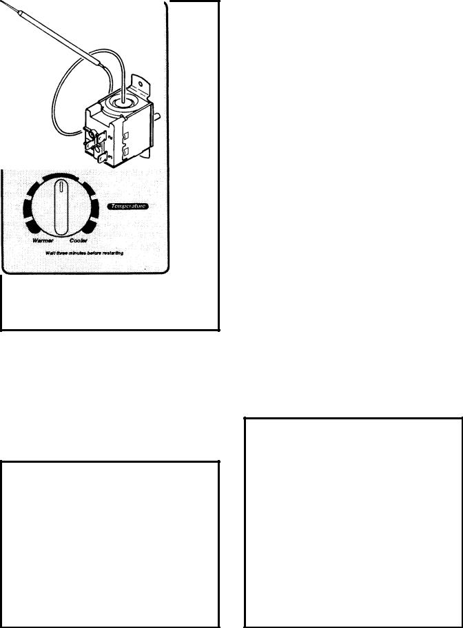
Figure 7: SYSTEM CONTROL PANEL
(Heat Pump & Electric Heat Models)
7."Lo Heat" Position - fan operates on low speed, compressor or electric heater is on.
8."Fan Only" Position - operates on medium speed.
NOTE: Heat pump models with electric heat - in the heat position, heating element only will be energized when outdoor temperature is below the operating range of the heat pump.
Figure 8: SYSTEM CONTROL SWITCH
(Heat Pump & Electric Heat Models)
SYSTEM CONTROL SWITCH - TEST
Disconnect leads from control switch. Turn control to position being tested (see Figure 8.) There must be continuity as follows:
1."Off" Position - no continuity between terminals.
2."Lo Cool" Position - between terminals "C" and "3", "C2" and "2", "LO" and "M/S", "AR" and "5".
3."Med Cool" Position - between terminals "C" and "3", "C2" and "2", "M" and "M/S", "AR" and "5".
4."Hi Cool" Position - between terminals "C" and "3", "C2" and "2", "H" and "M/S", "AR" and "5".
5."Hi Heat" Position - between terminals "C" and "1", "C2" and "4", "H" and "M/S", "AR" and "5".
6."Med Heat" Position - between terminals "C" and "1", "C2" and "4", "M" and "M/S", "AR" and "5".
7."Lo Cool" Position - between terminals "C" and "1", "C2" and "4", "LO" and "M/S", "AR" and "5".
8."Fan Only" Position - between terminals "L1" and "M".
THERMOSTAT - (see Figure 9)
A cross ambient thermostat is used on all heat pump and electric heat units. In addition to cycling the unit in a heating or cooling operation, the thermostat will terminate the cooling cycle in the event ice forms on the evaporator coil, in this case the thermostat functions as a de-ice control. A resistor (anticipator) is positioned
Figure 9: THERMOSTAT
TTJ-0197 (1/97) |
(Page 19 of 64) |
 Loading...