


BBR Service Manual |
Table of Contents/Section 1.1 |
|
|
Section No. |
Content/Service Operation |
Create/Update |
|
1.1 |
Table of Contents |
|
10/14/08 |
1.2A |
Franke Warranty Statement |
|
4/23/07 |
1.2B |
Franke Service Commitment |
|
4/23/07 |
1.3 |
BBR Trouble Shooting Tables |
|
7/17/07 |
1.4 |
Shelf Display Components – Old & New Wire Form |
10/13/08 |
|
1.5 |
BBR Parts List & Component Diagrams |
|
10/13/08 |
1.6 |
BBR Electric Schematics |
|
5/8/07 |
[General Part Replacement] |
|
|
|
2.1 |
General Service Instructions & Warnings |
|
10/13/08 |
2.2 |
Glass Door Replacement |
|
10/13/08 |
2.3 |
Door Bottom Roller Replacement |
|
6/12/07 |
2.4 |
Door-Open Latch Replacement |
|
6/12/07 |
2.5 |
Door Frame Replacement |
|
10/13/08 |
2.6 |
Display Light Bulb & Fixture Replacement |
|
6/12/07 |
2.7 |
(In-Case) Thermometer Replacement |
|
5/1/07 |
2.7A |
Remote Temp. Display Replacement [Newer Models] |
6/29/07 |
|
2.8 |
Power ON/OFF Switch Replacement |
|
10/13/08 |
2.9 |
Mechanical Thermostat Replacement [BBR-45 ONLY] 5/4/07 |
||
2.9A |
Digital temperature Controller Replacement |
|
6/28/07 |
2.10 |
Digital Temperature Sensor Replacement |
|
6/29/07 |
2.10A |
Evaporator Coil Defrost Sensor Replacement |
|
7/17/07 |
2.11 |
Condensate Collection Heater Replacement |
|
6/12/07 |
2.12 |
Power Cord Replacement |
|
6/13/07 |
[Part or Component Adjustments] |
|
|
|
3.1 |
Thermostat/Adjust Set Temperature [Older BBR-45] |
10/14/08 |
|
3.1A |
Digital Set Temperature Adjustment [Newer Models] |
10/14/08 |
|
3.2 |
Door Alignment/Roller Adjustment |
|
6/13/07 |
[Refrigeration System Repair & Replacement] |
|
|
|
4.1 |
Basic [Operator] Maintenance Procedures |
|
5/7/07 |
4.2 |
Condenser Fan Motor Replacement |
|
5/7/07 |
4.3 |
Evaporator Fan Motor Replacement |
|
5/1/07 |
4.4 |
Evaporator Coil Replacement |
|
6/13/07 |
4.5 |
Start Relay & Replace Start Capacitor Replacement |
5/8/07 |
|
4.6 |
Check System [Refrigerant] Pressure/Leaks |
|
6/13/07 |
4.7 |
Repair System [Refrigerant] Leak |
|
6/13/07 |
4.8 |
Filter/Drier Replacement |
|
6/13/07 |
4.9 |
Expansion Valve Replacement |
|
10/14/08 |
4.10 |
Replace Condenser/Compressor Package |
|
5/8/07 |
Service Bulletins |
|
|
|
5.1 |
Adding 90-degree Elbow to Drain Line |
|
2/7/07 |
5.2 |
Evaporator Drain Pan Retrofit [Kit No. 18002648] |
11/1/07 |
|
5.3 |
Door & Frame Kit [As Needed - BBR-36 ONLY] |
|
9/16/08 |
Rev. 9 10/14/08
For Technical Support, Call 800-537-2653. |
Copyright 2007 Franke, Inc. All rights reserved. |

BBR Service Manual |
Warranty/Section 1.2A |
|
|
Franke New Equipment
Limited Warranty
Franke Foodservice Systems (“Franke”) warrants new equipment manufactured in Franke’s own facilities and installed in the United States and Canada to be free of defects due to poor materials or workmanship for the period of time listed below (following the date of original installation):
Franke-Manufactured Equipment
Stainless Steel Surfaces – Life of the equipment
Compressor -- 5 Year Extended Warranty, as detailed below
All Other Components – 1 Years Parts and Labor
5-Year Extended Compressor Warranty
One Year from Date of Installation – Parts & Labor
2nd through 5th Year from Date of Installation – Parts only
In accordance with the compressor manufacturer’s policy, the serial number plate affixed to the compressor must be returned with the service invoice before reimbursement will be made.
Exclusions. Certain Franke parts that are expendable by nature and that need to be replaced frequently may not be covered. Franke is not liable under these warranties for repairs or damages due to improper operation, attempted repairs or installation by unauthorized persons, alterations, water quality, abuse, fire, flood or acts of God. Additionally, this warranty may be voided in the case of:
Failure to follow Franke instructions for use, care or maintenance Removal, alteration or defacing of the Franke-affixed serial number
This warranty is conditional upon Franke receiving notice of any defect subject to this warranty within thirty (30) days of its original discovery by the Buyer.
Other Equipment (Not Manufactured by Franke)
Equipment not manufactured by Franke (commonly known as “buyouts” or purchased goods) and manufactured by other entities is covered by the warranties, if any, of such third-party manufacturers. Where such third party manufacturers provide warranties on any or all portions of said “buyouts,” Franke agrees to transfer all such warranties to the Buyer.
Rev. 2. 4/07
For Technical Support, Call 800-537-2653. |
Copyright 2007 Franke, Inc. All rights reserved. |

BBR Service Manual |
Service Commitment/Section 1.2B |
|
|
FRANKE SERVICE COMMITMENT
SERVICE COMMITMENT
Franke Foodservice Systems’ Technical Support Department and its third-party Service Network are committed to meeting the unique service needs of restaurant operators. We strive to provide the following response times to service requests for Franke-manufactured equipment:
1. Provide contact with the customer…
–Within 30 minutes of request for service during normal business hours
–Within 90 minutes after normal business hours (including weekends)
2.Perform service visit
–The same day for emergency service*
–Within 24 hours for standard service
3.Target a 90% “first call” fix rate
4.Provide 90-day warranty on service performed
*For the purposes of this warranty, “emergency” is defined as an equipment operating condition that poses an immediate risk to the safety of restaurant workers or customers.
This response time breakdown applies throughout the week and weekend. Due to varying customer locations, and varying service agent locations and schedules, response rates may occasionally be extended. In these situations, Franke Technical Support will work directly with the customer to find mutually suitable options. Franke reserves the right to use service agents outside of the stated Service Network.
SERVICE NETWORK - United States and Canada
Franke fully supports and is a member of the National Service Cooperative (“NSC”), the leading independent provider of factory-authorized service in North America. Franke provides 24-hour, 7-day response to customer service requests through its own Call Center and that of the NSC.
Whenever possible, Franke selects service agents who belong to the Commercial Food Equipment Service Association. This trade association currently has more than 450 members representing the U.S., Canada, Mexico and Puerto Rico.
When Franke cannot select a CFESA member, it nonetheless adheres to the CFESA standard for qualified service agents in North America. Among them are:
•24 Hour emergency service
•Factory authorized warranty service
•Factory trained and certified technicians
•OEM parts availability
•System for communication with field technicians
Performance of service agents, including their parts stocking abilities, call response time, service rates and customer satisfaction are monitored by the Franke Field Service Department via online, written and phone surveys. Franke Technical Support updates this Service Network list annually.
CONTACT INFORMATION: Franke Technical Services
1-800-5FRANKE (1-800-537-2653) and select option 5) TechSupport@Franke.com
Rev. 1. 10/06
For Technical Support, Call 800-537-2653. |
Copyright 2007 Franke, Inc. All rights reserved. |

|
BBR Service Manual |
Advanced Troubleshooting Guide / Section 1.3 |
|||||||||
|
|
|
|
|
|
|
|
|
|
|
|
|
|
|
|
|
|
|
|
|
|
|
|
|
|
The Problem |
|
Possible Cause |
|
What To Check & Do |
|
||||
|
|
|
|
|
|
|
|
Breaker OK? Yes = Continue; No = Call |
|
||
|
Switch ON but |
Power not available to |
electrician |
|
|||||||
|
Power Not “ON” |
unit? |
|
|
Receptacle OK? Yes = Continue; No = Call |
|
|||||
|
|
|
|
|
|
|
|
electrician |
|
||
|
|
|
|
Power cord OK? |
Yes = Continue; No = Replace power cord set. |
|
|||||
|
|
|
|
|
|
|
|
Per Section 2.12. |
|
||
|
|
|
|
|
|
|
|
|
Unplug refrigerated case power cord for 1 hour, |
|
|
|
|
|
|
|
Compressor thermal |
|
|
then retry. If problem reoccurs: |
|
|
|
|
|
|
|
|
overload tripped? |
|
|
1. Ensure air filter is maintained per PM |
|
|
|
|
|
|
|
|
|
|
|
|
Service Instructions |
|
|
|
|
|
|
|
|
|
|
|
2. Ensure condenser coil is clear of debris |
|
|
|
|
|
|
|
|
|
|
|
and cleaned, per PM Service Instructions |
|
|
|
|
|
|
|
Power disconnected to |
|
|
Check input voltage to temperature controller. |
|
|
|
|
|
|
|
|
|
|
|
|
|||
|
|
Main Power “ON” |
|
|
temperature controller |
|
|
Replace wiring harness if damaged. |
|
|
|
|
|
But Compressor |
|
|
Temperature controller |
|
|
Check output voltage at temperature controller. |
|
|
|
|
|
Does Not Run |
|
|
disconnected from |
|
|
Replace wiring harness to Condenser, if |
|
|
|
|
|
|
|
|
condensing unit |
|
|
damaged |
|
|
|
|
|
|
|
|
Sensor cable is damaged |
|
|
Connect or replace sensor cable per Section |
|
|
|
|
|
|
|
|
|
|
|
|
|||
|
|
|
|
|
or disconnected from |
|
|
2.10 |
|
|
|
|
|
|
|
|
controller to refrigeration |
|
|
|
|
|
|
|
|
|
|
|
compartment |
|
|
|
|
|
|
|
|
|
|
|
Temperature controller is |
|
|
Replace defective component per Section 2.9 or |
|
|
|
|
|
|
|
|
|
|
|
|
|||
|
|
|
|
|
defective |
|
|
|
2.9A |
|
|
|
|
|
|
Set point too high |
Adjust thermostat setting, per Section 3.1 |
|
|||||
|
|
|
|
|
|
|
|||||
|
|
|
|
Door is being latched or |
Discuss case loading and use procedures with |
|
|||||
|
|
|
|
blocked open for extended |
unit manager and crew. |
|
|||||
|
|
|
|
periods. |
|
|
|
|
|
|
|
|
|
|
|
Door frame damaged or |
Inspect glass doors and door tracks for damage. |
|
|||||
|
Compressor Is |
thermo-pane seal has |
If needed, replace per Section 2.2 |
|
|||||||
|
failed |
|
|
|
|
|
|
||||
|
Running But Case |
|
|
|
|
|
|
||||
|
Evaporator fan not |
Check wiring and inspect fan for blockage. |
|
||||||||
|
Does Not Cool To |
functioning |
Replace evaporator fan motor if necessary, per |
|
|||||||
|
34 to 40° F |
|
|||||||||
|
|
|
|
|
Section 4.3 |
|
|||||
|
|
|
|
|
|
|
|
|
|||
|
|
|
|
Evaporator coil blocked |
Check Troubleshooting Problem: Evaporator Is |
|
|||||
|
|
|
|
with ice |
|
|
Blocked With Ice. Page 2 |
|
|||
|
|
|
|
Refrigerant charge is not |
Inspect service valves, lines, joints and |
|
|||||
|
|
|
|
correct |
|
|
components for signs of leaks, kinks or |
|
|||
|
|
|
|
|
|
|
|
restrictions. |
|
||
|
|
|
|
|
|
|
|
Service condensing unit per Section 4.6 |
|
||
|
|
|
|
|
|
|
|||||
|
|
|
|
Condensing unit does not |
Inspect and test condenser electrical components |
|
|||||
|
|
|
|
start |
|
|
for defects (start-capacitor, run-capacitor, start- |
|
|||
|
|
|
|
|
|
|
|
relay, condenser fan, compressor…) |
|
||
|
|
Evaporator Is |
|
|
Thermostat set point is too |
|
|
Adjust thermostat setting, per Section 3.1. |
|
|
|
|
|
|
|
|
|
|
|
||||
|
|
Blocked With Ice. |
|
|
low. |
|
|
|
|
|
|
|
|
|
|
|
|
|
|
|
Continued… |
|
|
For Technical Support, Call 800-537-2653. |
Copyright 2006 Franke, Inc. All rights reserved. |

|
BBR Service Manual |
Advanced Troubleshooting Guide / Section 1.3 |
|||||||||
|
|
|
|
|
|
|
|
|
|
|
|
|
|
|
|
|
|
|
|
|
|
|
|
|
|
The Problem |
|
Possible Cause |
|
What To Check & Do |
|
||||
|
|
|
|
|
Door is being latched or |
|
|
Defrost coil. Discuss case loading and use |
|
|
|
|
|
|
|
|
blocked open for extended |
|
|
procedures with unit manager and crew. |
|
|
|
|
|
|
|
|
periods. |
|
|
|
|
|
|
|
|
|
|
|
Door frame is damages or |
|
|
Inspect glass doors and door tracks for damage. |
|
|
|
|
|
Evaporator Is |
|
|
glass thermo-pane seal |
|
|
If required, replace per Section 2.2. |
|
|
|
|
|
Blocked With Ice… |
|
|
has failed. |
|
|
|
|
|
|
|
|
continued. |
|
|
Evaporator fan is not |
|
|
Check wiring and fan for blockage. Replace |
|
|
|
|
|
|
|
|
functioning. |
|
|
evaporator fan motor, if necessary per Section |
|
|
|
|
|
|
|
|
|
|
|
|
4.3. |
|
|
|
|
|
|
|
Automatic defrost function |
|
|
Check defrost operation buy pressing and holding |
|
|
|
|
|
|
|
|
|
|
|
|
|||
|
|
|
|
|
of electronic control is not |
|
|
bottom button on digital display. If display does |
|
|
|
|
|
|
|
|
working. |
|
|
|
not go to ‘dEF’ check defrost sensor for damage |
|
|
|
|
|
|
|
|
|
|
|
or improper placement. |
|
|
|
|
|
|
|
Defrost sensor is not |
|
|
Check defrost sensor location at rear-center of |
|
|
|
|
|
|
|
|
properly placed in coil. |
|
|
coil. In necessary, move sensor to area of |
|
|
|
|
|
|
|
|
|
|
|
|
greatest frost buildup. |
|
|
|
|
|
|
|
Refrigeration charge is not |
|
|
Inspect service valves, lines, joints and |
|
|
|
|
|
|
|
|
correct. |
|
|
|
components for signs of leaks, kinks or |
|
|
|
|
|
|
|
|
|
|
|
restrictions. If damage or leaks are found, repair |
|
|
|
|
|
|
|
|
|
|
|
or replace components per Sections: 4.7, 4.8 or |
|
|
|
|
|
|
|
|
|
|
|
4.9. |
|
|
|
Compressor is |
Sensors not mounted |
Make sure that air and coil sensors are |
|
|||||||
|
cooling and |
correctly. |
|
|
connected and mounted correctly, per Sections |
|
|||||
|
display is reading |
Sensors not plugged into |
2.10 and 2.10A. |
|
|||||||
|
in normal range |
controller properly. |
|
|
|
|
|||||
|
but ON-times are |
Sensors are reversed. |
Make sure that sensors are not reversed with air |
|
|||||||
|
short and actual |
|
|
|
|
sensor in coil and coil sensor in air sensor |
|
||||
|
case air |
|
|
|
|
location. |
|
||||
|
temperature is |
Sensors or controller is/are |
Check sensors and controller. Replace as |
|
|||||||
|
NOT that cold. |
failing. |
|
|
needed per Sections: 2.9A, 2.10 and/or 2.10A. |
|
|||||
Rev. 2 7/07
For Technical Support, Call 800-537-2653. |
Copyright 2006 Franke, Inc. All rights reserved. |
BBR Service Manual |
Shelf Display Components / Section 1.4 |
|
|
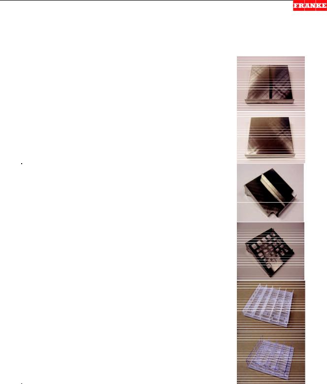
Old Style Stainless Steel & Plastic Shelf System Components
Part No. & Description |
Product/Display Application |
Component Photo |
P/N: 18001770 -- Stainless |
Horizontal [lay-down] stocking of |
|
steel bottom shelf with |
plastic or glass beverage bottles |
|
center divider and sloped |
or cans; Flat stocking of plastic or |
|
design with front stop, to |
foam salad containers or other |
|
allow displayed product to |
pre-packaged product. |
|
roll or slide forward. |
|
|
|
|
|
P/N: 17006047 -- Stainless |
Flat stocking of plastic or foam |
|
steel bottom shelf with |
salad containers or other pre- |
|
sloped design with front |
packaged product; or to support |
|
stop to allow displayed |
White Plastic Shelf Grate Part |
|
product to roll or slide |
Number 19001001. |
|
forward. |
|
|
P/N: 18001771 -- Stainless |
Horizontal [lay-down] stocking of |
|
steel hanging shelf with |
plastic or glass beverage bottles; |
|
center divider, bottle access |
Flat stocking of plastic or foam |
|
cutout and sloped design |
salad container or other pre- |
|
with front stop allow |
packaged product. |
|
displayed product to roll |
|
|
forward. |
|
|
P/N: 17006146 -- Stainless |
Designed to support and work |
|
steel hanging shelf with |
with Part Number 190001001 |
|
perforated bottom and |
White Plastic Shelf with tall Clear |
|
vertical tabs to secure |
Plastic Dividers. |
|
plastic dividers. [Shelf is |
|
|
perforated to provide good |
|
|
air flow.] |
|
|
P/N: 19001001 -- White |
For standing display of milk |
|
plastic shelf grate with |
cartons, juice boxes and other |
|
adjustable vertical plastic |
small containers. It is typically set |
|
dividers forming five |
on the Solid Stainless Steel |
|
separate display rows. |
Bottom Shelf. |
|
|
|
|
P/N: 19001000 -- White |
For standing display of water or |
|
plastic shelf grate with |
other beverage bottles. It is set on |
|
taller, clear plastic |
the perforated Stainless Steel |
|
adjustable dividers forming |
Hanging Shelf. |
|
four separate display rows. |
|
|
|
|
|
Rev. 2 [10/08]
For Technical Support, Call 800-537-2653. |
Copyright 2008 Franke, Inc. All rights reserved. |
BBR Service Manual |
Shelf Display Components / Section 1.4 |
|
|
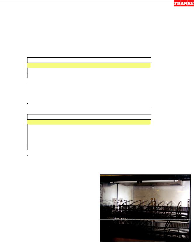
New Style Wire Form Shelf System Components
Franke Bottled Beverage Refrigerators (BBR-36 & BBR-45 Models) now ship from the factory with wire display shelf components assembled but shipped in a separate cardboard carton, ready for installation.
Wire Shelving Kit Components & Part Numbers:
BBR-36” – New Unit Wire Shelf Kit No. 19001889
BBR-36” – Retrofit Wire Shelf Kit No. 18002674 [* Includes]
Part No. |
Description |
Quantity |
19001595 |
Full 36” Wide Upper Shelf |
1 |
19001594 |
Sectional Bottom Shelf |
2 |
19001380 |
Upper Shelf Adjustable Dividers |
8 |
19001000 |
Bottom Shelf Adjustable Dividers |
6 |
*17007299 |
Upper Shelf Mounting Brackets |
3 |
*3586580 |
Shelf Mounting Bracket Screws |
12 |
19001381 |
Assembly/Setup Instructions |
1 |
BBR-45” – New Unit Wire Shelf Kit No. 19001888
BBR-45” – Retrofit Wire Shelf Kit No. 18002378 [* Includes]
Part No. |
Description |
Quantity |
19001378 |
Full 45” Wide Upper Shelf |
1 |
19001377 |
Sectional Bottom Shelf |
3 |
19001380 |
Upper Shelf Adjustable Dividers |
12 |
19001000 |
Bottom Shelf Adjustable Dividers |
7 |
*17007299 |
Upper Shelf Mounting Brackets |
4 |
*3586580 |
Shelf Mounting Bracket Screws |
16 |
19001381 |
Assembly/Setup Instructions |
1 |
Retrofit of Wire Shelf System
For field replacement of an existing Stainless Steel & Plastic Shelf System, obtain Wire Shelving Kit No. 18002674 for 36” wide BBR or Kit No. 18002378 for 45” wide models. Retrofit Kits include detailed installation instructions: Doc. No. 19001381.
For Technical Support, Call 800-537-2653. |
Copyright 2008 Franke, Inc. All rights reserved. |

BBR Service Manual |
Key Parts Lists / Section 1.5 |
|
|
Basic Repair Parts List
|
[Also See Section 2.1 – For Truck Stock List] |
|
|
BBR - 36 |
BBR - 45 |
Description |
Qty. |
19001266 |
19000992 |
Sliding Glass Door Frame |
1 ea. |
19001267 |
19000993 |
Inner/Left Door |
1 ea. |
19001268 |
19000994 |
Outer/Right Door |
1 ea. |
3126151 |
3126151 |
Power ON Switch |
1 ea. |
19000962 |
19000962 |
In-case Thermometer |
1 ea. |
19001164 |
19001164 |
Case Light Fixture, with Bulb 1) |
1 ea. |
-- |
19000023 |
Danfoss Mechanical Thermostat 2) |
1 ea. |
19001104 |
19001104 |
Digital Temperature Control 2) |
1 ea. |
19001172 |
19001172 |
Digital Temperature Sensor |
1 ea. |
19000470 |
19000470 |
Digital Defrost Sensor |
1 ea. |
19000436 |
19000436 |
Remote Temperature Display |
1 ea. |
19001171 |
19001171 |
Remote Display Cable |
1 ea. |
19000958 |
19000958 |
Condensate Collection Heater |
1 ea. |
18001787 |
18001787 |
Condensate Collection Assembly |
1 ea. |
3589854 |
3589854 |
Condenser Fan Motor |
1 ea. |
19001293 |
19000454 |
Evaporator Fan Motor |
1 ea. |
19000998 |
19000998 |
Evaporator Coil |
1 ea. |
600024 |
600024 |
Start Capacitor |
1 ea. |
19001083 |
19001083 |
Start Relay |
1 ea. |
19001079 |
19001079 |
Compressor, Danfoss TF4 |
1 ea. |
19000959 |
19000959 |
Condensing Unit, ¼-HP |
1 ea. |
19001189 |
19000497 |
Thermostatic Expansion Valve |
1 ea. |
19000282 |
19000282 |
8’ cord set with plug |
1 ea. |
19001328 |
19001328 |
Sliding Door Roller Assembly |
4 ea. |
19001329 |
19001329 |
Door Hold-Open Latch |
2 ea. |
19002321 |
19001330 |
Door-Close Spring Assembly |
2 ea. |
19002322 |
19001331 |
Bumper Gasket for Outer/RH Door |
1 ea. |
19002323 |
19001332 |
Bumper Gasket for Inner/LH Door |
1 ea. |
19002324 |
19001333 |
Sealer Gasket for Outer/RH Door |
1 ea. |
NOTES:
1)Bulb for light fixture is a T5 14W, FH 14W/840 HE, and available locally.
2)Models built prior to May 2007 have an electro-mechanical thermostat. Newer models have digital temperature controls.
Rev. 2 10/08
For Technical Support, Call 800-537-2653. |
Copyright 2007 Franke, Inc. All rights reserved. |
BBR Service Manual |
Electric Schematics / Section 1.6 |
||
|
|
|
|
|
|
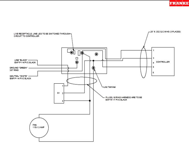
BBR Wiring Harness |
|
|
|
|
|
|
|
|
|
Rev. 1 5/07
For Technical Support, Call 800-537-2653. |
Copyright 2007 Franke, Inc. All rights reserved. |
BBR Service Manual |
Parts Replacement / Section 2.1 |
2.1An Introduction To BBR Service Manual
The Basics:
1)Technicians should be authorized to work on Franke Equipment and be EPA Certified and qualified to diagnose and repair refrigeration equipment.
2)The Franke Bottled Beverage Dispenser [BBR] is a wall mounted display refrigerator designed to provide easy crew access to beverages and chilled prepared foods.
3)This unit operates on 120-volt power and is provided with a grounded plug and 8’ power cord.
WARNING:
Unplug unit from its120-volt power source whenever servicing electrical components or removing side service access panels. Failure to unplug unit may result in electric shock, burns or death.
4)The BBR refrigeration system is charged with 16 ounces (.45 kg) of ozone-safe R404A refrigerant. See unit Data Plate and use site glass provided, when filling.
5)Only use R404A refrigerant when recharging this unit.
6)Always verify proper unit cleaning before replacing or repairing components. [See Section 4.1]
Suggested [On-Truck] Repair Parts:
We suggest the following to ensure a first-trip fix of the BBR:
BBR-36 |
BBR-45 |
Description |
Qty. |
19001266 & 19000992 |
Sliding Glass Door Frames |
1 ea. |
|
19001267 & 19000993 |
Inner/Left Doors |
1 ea. |
|
19001268 & 19000994 |
Outer/Right Doors |
1 ea. |
|
3126151 |
Power ON Switch |
1 ea. |
|
19000962 |
In-case Thermometer |
1 ea. |
|
19001164 |
Case Light Fixture, with Bulb1) |
2 ea. |
|
--19000023 Danfoss Mechanical Thermostat2) 1 ea.
19001104 |
Digital Temperature Control |
1 ea. |
19001172 |
Digital Temperature Sensor |
1 ea. |
19000470 |
Digital Defrost Sensor |
1 ea. |
19000436 |
Remote Temperature Display |
1 ea. |
19001171 |
Remote Display Cable |
1 ea. |
19000958 |
Condensate Collection Heater |
1 ea. |
18001787 |
Condensate Collection Assembly |
1 ea. |
3589854 |
Condenser Fan Motor |
1 ea. |
19001293 & 19000454 |
Evaporator Fan Motors |
1 ea. |
19000998 |
Evaporator Coil |
1 ea. |
600024 |
Start Capacitor |
1 ea. |
19001083 |
Start Relay |
1 ea. |
19001079 |
Compressor, Danfoss TF4 |
1 ea. |
19000959 |
Condensing Unit, ¼-HP |
1 ea. |
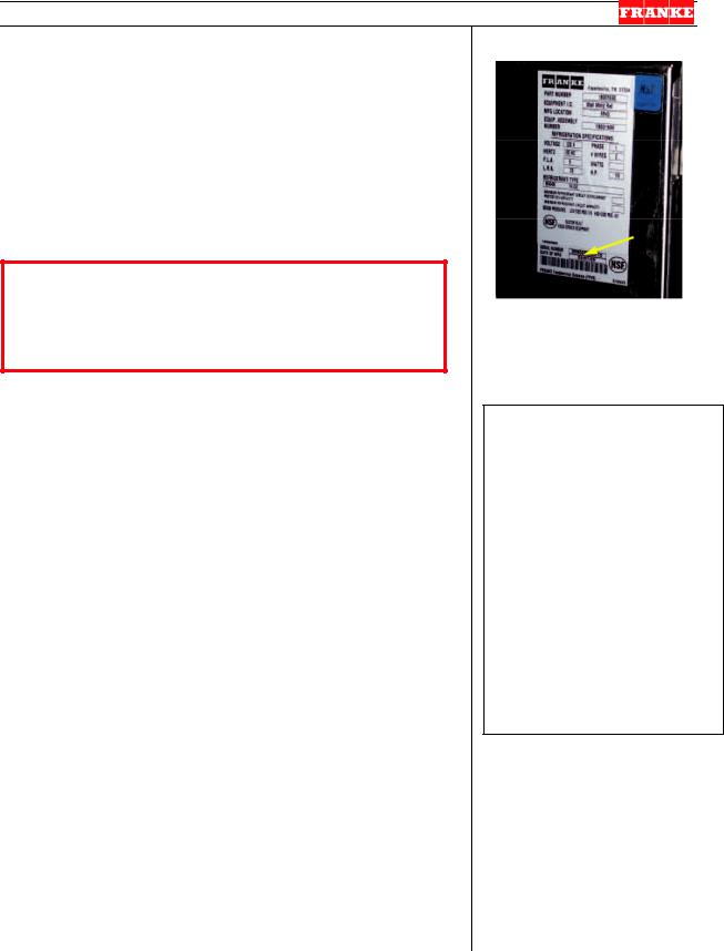
[Photo 1]
The BBR Unit Serial Number is located adjacent to the Model Number & Data sticker, which is on the left side, when facing unit.
Tools Required:
[For Mechanical Systems Repair]
3/8” screw driver ¼” screw driver
1/16” “mini” screw driver 1/8” Allen/hex wrench 3/16” Allen/hex wrench 5/32” Allen/hex wrench 5 mm Allen/hex wrench 13 mm Allen/hex wrench 7/16” box/socket wrench Razor knife
Needle nose pliers Small wire cutters Rubber mallet Plastic Wire Ties
[Also See Section 4.1A]
Rev. 4 10/08
For Technical Support, Call 800-537-2653. |
Copyright 2007 Franke, Inc. All rights reserved. |
BBR Service Manual |
Parts Replacement / Section 2.1 |
|
|
Additional Suggested [On-Truck] Repair Parts:
We suggest the following to ensure a first-trip fix of the BBR:
BBR-36 |
BBR-45 |
Description |
Qty. |
19001189 & 19000497 |
Thermostatic Expansion Valves |
1 ea. |
|
19000282 |
8’ cord set with plug |
1 ea. |
|
19001328 |
Sliding Door Roller Assembly |
4 ea. |
|
19001329 |
Door Hold-Open Latch |
2 ea. |
|
19002321 & 19001330 |
Door-Close Spring Assemblies |
2 ea. |
|
19002322 & 19001331 |
Bumper Gasket for Outer/RH Door 1 ea. |
||
19002323 & 19001332 |
Bumper Gasket for Inner/LH Doors 1 ea. |
||
19002324 & 19001333 |
Sealer Gasket for Outer/RH Doors |
1 ea. |
|
NOTES:
1.Bulb for light fixture is a T5 14W, FH 14W/840 HE, and available locally.
2.Models built prior to May 2007 have an electromechanical thermostat. Newer models have digital temperature controls.
For Technical Support, Call 800-537-2653. |
Copyright 2007 Franke, Inc. All rights reserved. |
BBR Service Manual |
Parts Replacement / Section 2.2 |
2.2Glass Sliding Door Replacement
For Doors On: |
BBR-36 Models |
BBR-45 Models |
Outer/Right: |
P/N 19001268 |
P/N 1900994 |
Inner/Left: |
P/N 19001267 |
P/N 1900993 |
When Should A Door Be Replaced?
The BBR Sliding Glass Doors are fabricated with sealed double thermal pane, tempered safety glass panels, for strength and to provide better insulating value. The Outer/Right or Inner/Left door should be replaced if:
either inner or outer pane is cracked or broken; fog or condensate appears between the glass [The gas thermo-pane seal has broken.];
If the plastic doorframe is broken, chipped or interferes with closing or sealing the door, See Section 2.5.
CAUTION
If door grass is broken, use gloves and caution when handling door. Ensure case is emptied and inspected for any broken glass. Inspect door tracks for any glass and use caution when disposing of all broken glass.
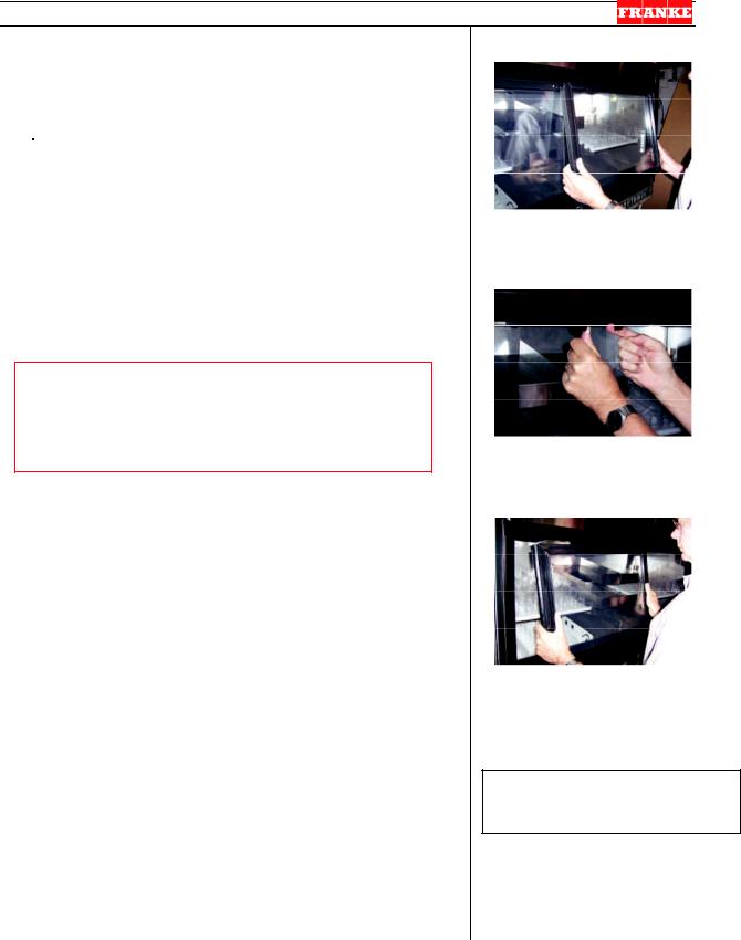
1)Remove door to be replaced by opening it enough to grasp both sides; lift door up into upper channel, pull bottom of door forward; pull door down and free of spring closing stud.
2)Remove new door from protective packaging.
3)Grasp new door with both hands; nose [left/right] top leading edge against spring closing stud and slid stud against spring pressure left or right until door top frame slides into top track.
4)Angle door bottom into bottom track and allow door to slide closed.
5)Test the new Glass Door by:
6)Slide OPEN that door, release it and allow it to close. Did closing spring roll it back and fully close door?
7)Check door seal against cabinet frame. Is the door square with the case frame? If doors do not seal against frame, See Section 3.2 for instructions on adjusting door alignment.
[Photo 1]
To remove door lift up into upper track until bottom clears lower track then angle out, bottom-first.
[Photo 2]
The Door-Close Springs have a plastic stud that engages the leading top edge of each door.
[Photo 3]
Engage spring stud with top leading edge of door and push against spring tension until top of door slides into upper track.
Tools Required:
NONE Required
8)If door is functioning properly, return BBR to service.
Rev. 3 10/08
For Technical Support, Call 800-537-2653. |
Copyright 2007 Franke, Inc. All rights reserved. |
BBR Service Manual |
Parts Replacement / Section 2.3 |
2.3Door Bottom Roller Replacement [Part No. 190001328]
When Should Door Rollers Be Replaced?
Each BBR Sliding Glass Door rolls on two metal rollers set into the bottom doorframe. NOTE: Before replacing, inspect bottom door track for broken glass or any debris that may interfere with door movement. If doors are difficult to roll back or if plastic doorframe is being gouged or abraded by door bottom, inspect and replace one or both Door Bottom Rollers.
1)Remove door to be inspected by opening it enough to grasp both sides; lift door up into upper channel, pull bottom of door forward; pull door down and free of spring closing stud.
2)Turn the door bottom UP and inspect both metal rollers. They should roll freely with little resistance.
3)If one or both roller is corroded or will not roll freely, replace with P/N 190001328.
4)Use a ¼” nut driver to remove the two lock nuts securing the damaged door roller assembly.
5)Remove the wheel assembly. NOTE: There may be one or more small metal spacers on the screw studs. Leave them in place.
6)Place new door bottom roller assembly in bottom frame slot (on screw studs) and secure using the two ¼” lock nuts just removed. [Repeat steps 4 & 5 if replacing both rollers.]
7)Turn door right-side-up and nose [left/right] top leading edge against spring closing stud and slide stud against spring pressure [left or right] until door top frame slides into top track.
8)Angle door bottom into bottom track and allow door to slide closed.
9)Test the replacement roller(s) by:
10)Slide OPEN door, release it and allow it to close. Did the door roll back freely and fully close?
11)Check door seal against cabinet frame. If doors do not seal against frame, see Section 3.2 for instructions on adjusting door alignment.
12)If door is functioning properly, return BBR to service.
[Photo 1]
To remove door lift up into upper track until bottom clears lower track then angle out, bottom-first.
[Photo 2]
Use a ¼” nut driver to remove and replace two lock nuts that secure each door bottom roller.
[Photo 3]
To replace door engage spring stud with top leading edge of door and push against spring tension until top of door slides into upper track.
Tools Required:
¼” nut driver
Rev. 2 6/07
For Technical Support, Call 800-537-2653. |
Copyright 2007 Franke, Inc. All rights reserved. |

BBR Service Manual |
Parts Replacement / Section 2.4 |
2.4Glass Door Hold-Open Latch Replacement [Part No. 19001329]
A simple Door Hold-Open Latch is used to prop open either spring-loaded auto-close door, when loading or unloading product. You lift it up when door is near full OPEN position and insert tip in top channel slot or depression to hold door.
To replace this latch:
1)Remove door with broken or missing stop by opening it enough to grasp both sides; lift door up into top channel, pull bottom of door forward; pull door down and free of spring closing stud.
2)Place door on flat, clean work surface. Be careful not to mare or scratch glass.
3)Using medium Phillips screwdriver, remove screw and broken end of latch.
4)Take new stop [P/N: 19001329] and screw into hole in inside door frame
5)Grasp new door with both hands; nose [left/right] top leading edge against spring closing stud and slid stud against spring pressure left or right until door top frame slides into top channel.
6)Angle door bottom into bottom track and allow door to slide closed.
7)Test the replacement of the Door Hold-Open Latch by:
8)Slide open the door, flip up plastic latch to engage slot or depression in upper door channel. Release door. Does it stay open?
9)Slide door a little further open, against spring tension. Latch should disengage and swing down, out of the way.
10)If latch is functioning properly, notify manager of fix.
[Photo 1]
A plastic latch is attached to the top/inside of each door leading edge. It swivels up to engage a depression or slot in upper door channel.
[Photo 2]
The Door-Close Springs have a plastic stud that engages the leading top edge of each door.
[Photo 3]
Engage spring stud with top leading edge of door and push against spring tension until top of door slides into upper track.
Tools Required:
Medium Philips Screwdriver
Rev. 2 6/07
For Technical Support, Call 800-537-2653. |
Copyright 2007 Franke, Inc. All rights reserved. |

BBR Service Manual |
Parts Replacement / Section 2.5 |
2.5Door Frame Replacement
[Part No. 19001266 – BBR-36 Models] [Part No. 19000992 – BBR-45 Models]
When Should The Door Frame Be Replaced?
The BBR Sliding Glass Doors should open easily and automatically close when released. Both doors should seal squarely against the left or right door jam. The Door Frame should be replaced if:
If the plastic door frame is broken, chipped or interferes with closing or sealing the door.
If either door doesn’t close square with side jam, try adjusting the door per Service Manual Section 3.2.
1)Turn OFF power at switch and unplug power cord from 120-volt outlet.
2)Remove all refrigerated product from case. IMPORTANT: Any perishable foods including milk should be placed in another refrigerator.
3)Remove both glass doors. Lift up and pull out door bottom, then pull down and out of upper track, releasing auto-close spring stud.
4)Remove all hanging shelf components to provide more room to work.
5)Use a medium Phillips screwdriver to remove the six door frame mounting screws: three in top track & three in bottom track.
6)Cut the silicon sealant bead applied around the plastic door frame where it meets cabinet.
7)Remove old black plastic door frame from unit front.
8)Obtain and orient new Door Frame [P/N 19001266 (BBR-36) or P/N 19000992 (BBR-45)] with the larger flange OUT and the spring door closers on top/UP.
9)Insert new plastic door frame in cabinet opening. NOTE: Door frame will flex to help with press fit. Make sure outer frame flange is flush and square with cabinet front.
10)Use power drill with 1/8” [3 mm] metal bit to drill six new holes through plastic frame track and stainless steel below. Locate one hole 3” [76 mm] from each side and on-center, in both top and bottom track.
11)Use self-tapping screws in all six holes to secure plastic door frame to cabinet.
12)Apply a smooth continuous bead of black silicone sealant to the full perimeter of both the inner and outer doorframe flange: top, sides and bottom. IMPORTANT: Take your time and ensure a neat continuous seal, to avoid condensate water leaks.
[Photo 1]
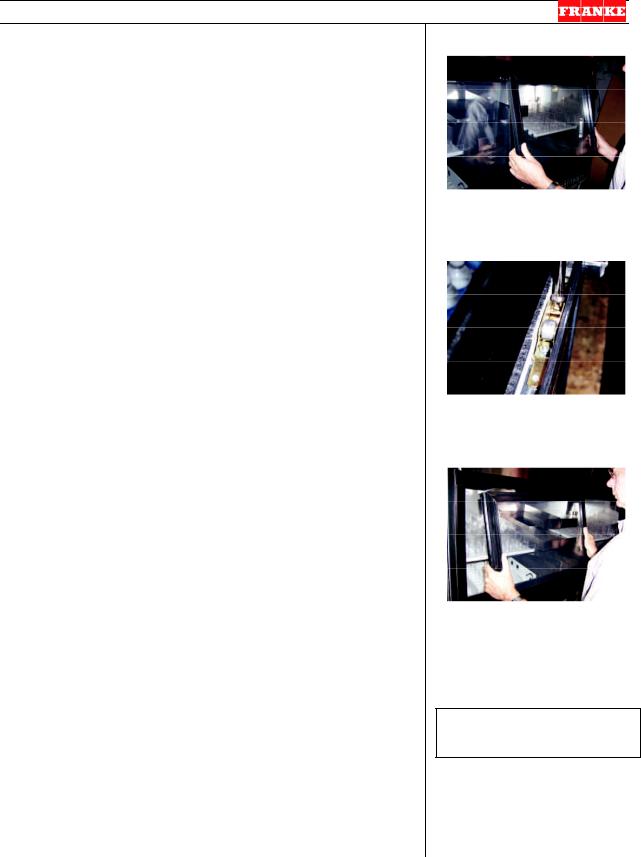
To remove doors lift up until bottom clears lower track then angle out, bottom-first.
[Photo 2]
Remove the three screws in the bottom track and three in upper door track that secure frame.
[Photo 3]
Insert new frame into cabinet opening until flush and square.
[Photo 4 – Upper Track View]
Drill 1/8” holes through frame and stainless steel, then secure frame with self-tapping screws.
Rev. 4 10/08
For Technical Support, Call 800-537-2653. |
Copyright 2007 Franke, Inc. All rights reserved. |
 Loading...