


GB
DK
SE
NO
FI
Instructions for use and installation
Cooker Hood
Betjeningsog installationsvejledning
Emhætte
Handbok för installation, användning och underhăll
Spisfläkt
Håndbok for installasjon bruk og vedlikehold
Kjøkkenvifte
Asennus-, käyttöja hoito-opas
Liesituuletin
FNE 905 XS ECS

INDEX
EN
RECOMMENDATIONS AND SUGGESTIONS |
..................................................................................................................... 3 |
CHARACTERISTICS ............................................................................................................................................................. |
4 |
INSTALLATION...................................................................................................................................................................... |
5 |
USE ........................................................................................................................................................................................ |
8 |
MAINTENANCE ..................................................................................................................................................................... |
9 |
EASY CLEANING TM .......................................................................................................................................................... |
10 |
INDHOLD
DK
RÅD OG ANVISNINGER ..................................................................................................................................................... |
13 |
APPARATBESKRIVELSE ................................................................................................................................................... |
14 |
INSTALLATION.................................................................................................................................................................... |
15 |
BRUG ................................................................................................................................................................................... |
18 |
VEDLIGEHOLDELSE .......................................................................................................................................................... |
19 |
EASY CLEANING TM .......................................................................................................................................................... |
20 |
INNEHÅLL |
SE |
REKOMMENDATIONER OCH TIPS ................................................................................................................................... |
23 |
EGENSKAPER..................................................................................................................................................................... |
24 |
INSTALLATION.................................................................................................................................................................... |
25 |
ANVÄNDING........................................................................................................................................................................ |
28 |
UNDERHÅLL........................................................................................................................................................................ |
29 |
EASY CLEANING TM .......................................................................................................................................................... |
30 |
INNHOLD
NO
ANBEFALINGER OG FORSLAG |
........................................................................................................................................ 33 |
EGENSKAPER..................................................................................................................................................................... |
34 |
INSTALLASJON................................................................................................................................................................... |
35 |
BRUK ................................................................................................................................................................................... |
38 |
VEDLIKEHOLD .................................................................................................................................................................... |
39 |
EASY CLEANING TM .......................................................................................................................................................... |
40 |
SISÄLTÖ |
FI |
OHJEET JA SUOSITUKSET ............................................................................................................................................... |
43 |
MITAT JA OSAT .................................................................................................................................................................. |
44 |
ASENNUS ............................................................................................................................................................................ |
45 |
KÄYTTÖ ............................................................................................................................................................................... |
48 |
HUOLTO .............................................................................................................................................................................. |
49 |
EASY CLEANING TM .......................................................................................................................................................... |
50 |
2
RECOMMENDATIONS AND SUGGESTIONS
 The Instructions for Use apply to several versions of this appliance. Accordingly, you may find descriptions of individual features that do not apply to your specific appliance.
INSTALLATION
•The manufacturer will not be held liable for any damages resulting from incorrect or improper installation.
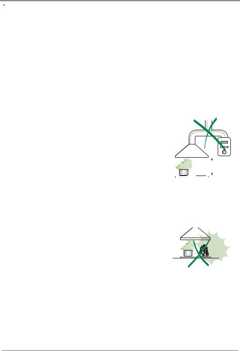
•The minimum safety distance between the cooker top and the extractor hood is 650 mm (some models can be installed at a lower height, please refer to the paragraphs on working dimensions and installation).
•Check that the mains voltage corresponds to that indicated on the rating plate fixed to the inside of the hood.
•For Class I appliances, check that the domestic power supply guarantees adequate earthing.
Connect the extractor to the exhaust flue through a pipe of minimum diameter 120 mm. The route of the flue must be as short as possible.
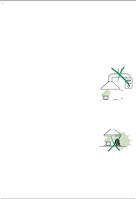
•Do not connect the extractor hood to exhaust ducts carrying combustion fumes (boilers, fireplaces, etc.).
•If the extractor is used in conjunction with non-electrical appliances (e.g. gas burning appliances), a sufficient degree of aeration must be guaranteed in the room in order to prevent the backflow of exhaust gas. The kitchen must have an opening communicating directly with the open air in order to guarantee the entry of clean air.
USE
• The extractor hood has been designed exclusively for domestic use to elimi- |
|
|
|
|
|
|
||
|
|
|
|
|
|
|||
nate kitchen smells. |
|
|
|
|
|
|
||
|
|
|
|
|
|
|||
• Never use the hood for purposes other than for which it has been designed. |
|
|
|
|
||||
|
|
650 mm min. |
||||||
• Never leave high naked flames under the hood when it is in operation. |
|
|
|
|
|
|
||
• Adjust the flame intensity to direct it onto the bottom of the pan only, making |
|
|
|
|
|
|
|
|
|
|
|
|
|
|
|
|
|
|
|
|
|
|
|
|
|
|
sure that it does not engulf the sides. |
|
|
|
|
|
|
||
•Deep fat fryers must be continuously monitored during use: overheated oil can burst into flames.
•Do not flambè under the range hood; risk of fire
•This appliance is not intended for use by persons (including children) with reduced physical, sensory or mental capabilities, or lack of experience and knowledge, unless they have been given supervision or instruction concerning use of the appliance by a person responsible for their safety.
•Children should be supervised to ensure that they do not play with the appli-
ance.
MAINTENANCE
• Switch off or unplug the appliance from the mains supply before carrying out any maintenance work.
•Clean and/or replace the Filters after the specified time period (Fire hazard).
•Clean the hood using a damp cloth and a neutral liquid detergent.
The symbol  on the product or on its packaging indicates that this product may not be treated as household waste. Instead it shall be handed over to the applicable collection point for the recycling of electrical and electronic equipment. By ensuring this product is disposed of correctly, you will help prevent potential negative consequences for the environment and human health, which could otherwise be caused by inappropriate waste handling of this product. For more detailed information about recycling of this product, please contact your local city office, your household waste disposal service or the shop where you purchased the product.
EN |
|
3 |
|
3 |

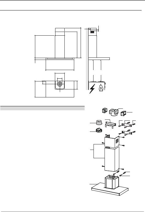
CHARACTERISTICS
|
|
Dimensions |
|
|
|
|
64 |
42 |
|
|
|
|
|
|
|
|
940 |
|
|
540 |
|
680 |
|
|
60 |
|
|
|
|
|
898 |
|
Min. |
Min. |
|
300 |
|
||
|
|
650mm |
650mm |
|
|
|
|
||
|
150 |
|
|
|
108 |
|
260 |
|
|
490 |
|
|
|
|
Components
Ref. Q.ty Product Components
11 Hood Body, complete with: Controls, Light, Blower, Filters
2 |
1 |
Telescopic Chimney comprising: |
2.1 |
1 |
Upper Section |
2.2 |
1 |
Lower Section |
9 |
1 |
Reducer Flange ø 150-120 mm |
10 |
1 |
Damper ø 150 |
14.1 |
2 |
Air Outlet Connection Extension |
15 |
1 |
Air Outlet Connection |
|
|
|
Ref. |
Q.ty |
Installation Components |
7.2.1 |
2 |
Upper Chimney Section Fixing Brackets |
7.3 |
1 |
Air Outlet Connection Support |
11 |
6 |
Wall Plugs |
12a |
6 |
Screws 4,2 x 44,4 |
12c |
6 |
Screws 2,9 x 9,5 |
|
Q.ty |
Documentation |
|
1 |
Instruction Manual |
15
14.1
7.3 |
12a |
7.2.1 |
11 |
|
9
10
2.1 |
12c |
|
2
2.2
11 |
12a |
1
EN |
|
4 |
|
4 |

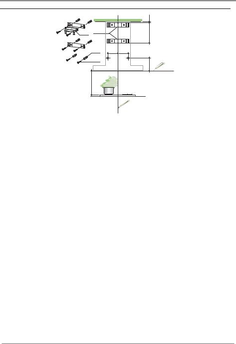
INSTALLATION
Wall drilling and bracket fixing
7.37.2.1
X 1÷2
11 |
116 |
116 |
12a |
|
|
650 min.
320
Wall marking:
•Draw a vertical line on the supporting wall up to the ceiling, or as high as practical, at the centre of the area in which the hood will be installed.
•Draw a horizontal line at 650 mm above the hob.
•Place bracket 7.2.1 on the wall as shown about 1-2 mm from the ceiling or upper limit aligning the centre (notch) with the vertical reference line.
•Mark the wall at the centres of the holes in the bracket.
•Place bracket 7.2.1 on the wall as shown at X mm below the first bracket (X = height of the upper chimney section supplied), aligning the centre (notch) with the vertical line.
•Mark the wall at the centres of the holes in the bracket.
•Mark a reference point as indicated at 116 mm from the vertical reference line and 320 mm above the horizontal reference line.
•Repeat this operation on the other side.
•Drill ø 8 mm holes at all the centre points marked.
•Insert the wall plugs 11 in the holes.
•Fix the lower bracket 7.2.1 using the 12a screws (4,2 x 44,4) supplied.
•Fix the upper bracket 7.2.1 and the air outlet connection support 7.3 together using the 2 screws 12a (4,2 x 44,4) supplied.
•Insert the two screws 12a (4,2 x 44,4) supplied in the hood body fixing holes, leaving a gap of 5-6 mm between the wall and the head of the screw.
EN |
|
5 |
|
5 |

|
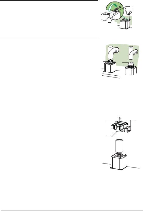
Mounting the hood body |
|
• |
Before attaching the hood body, tighten the two screws Vr lo- |
Vr |
|
cated on the hood body mounting points. |
|
|
|
|
• |
Hook the hood body onto the screws 12a. |
|
• Fully tighten the support screws 12a. |
|
|
• |
Adjust the screws Vr to level the hood body. |
12a |
Connections
DUCTED VERSION AIR EXHAUST SYSTEM |
|
|
When installing the ducted version, connect the hood to the |
|
|
chimney using either a flexible or rigid pipe ø 150 or 120mm, the |
|
|
choice of which is left to the installer. |
ø 150 |
ø 120 |
To install a ø 150 pipe |
10 |
9 |
• To install the dumper 10 |
|
10 |
• Fix the pipe in position using sufficient pipe clamps (not sup- |
|
|
plied). |
|
|
To install a ø 120 pipe
•To install a ø 120 mm air exhaust connection, insert the reducer flange 9 on the dumper 10.
•Fix the pipe in position using sufficient pipe clamps (not supplied).
•Remove any activated charcoal filters.
RECIRCULATION VERSION AIR OUTLET
•Insert the connection extension pieces laterally 14.1 in connection 15.
•Insert the Connector 15 into the Support bracket 7.3 and fix it with a screw.
•Make sure that the outlet of the extension pieces 14.1 is horizontally and vertically aligned with the chimney outlets.
•Connect the air outlet connection 15 to the hood body outlet
using either a flexible or rigid pipe ø 150 mm, the choice of which is left to the installer.
• Ensure that the activated charcoal filters have been inserted.
7.3 |
14.1 |
|
|
15 |
|
|
ø 150 |
EN |
|
6 |
|
6 |

ELECTRICAL CONNECTION
•Connect the hood to the mains through a two-pole switch having a contact gap of at least 3 mm.
•Remove the grease filters (see paragraph Maintenance) being sure that the connector of the feeding cable is correctly inserted in the socket placed on the side of the fan.
Flue assembly
Upper exhaust flue
•Slightly widen the two sides of the upper flue and hook them behind the brackets 7.2.1, making sure that they are well seated.
•Secure the sides to the brackets by using the 4 screws 12c (2,9 x 9,5) supplied.
•Make sure that the outlet of the extensions pieces is aligned with the chimney outlets.
Lower exhaust flue
• Slightly widen the two sides of the flue and hook them between the upper flue and the wall, making sure that they are well seated.
•Fix the lower part laterally to the hood body by using the 2 screws 12c (2,9 x 9,5) supplied.
7.2.1
12c |
2.1 
 2
2 
2.2
12c
EN |
|
7 |
|
7 |
USE
|
|
|
|
|
|
|
|
|
|
|
|
|
|
|
|
|
|
|
|
|
|
|
|
|
|
|
|
|
|
|
|
|
|
|
|
|
|
|
|
|
|
|
|
|
|
|
T1 |
|
T2 |
T3 |
|
|
|
||||||
|
|
|
|
|
|
|
|
L |
|||||||||||
|
|
|
|
|
|
|
|
|
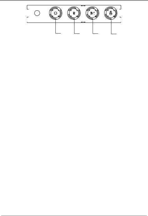
Control panel |
|
|
|
|
|
|
|
|
||
BUTTON |
LED |
FUNCTIONS |
|
|
|
|
|
|
|
|
|||||||||
T1 |
Speed |
On |
Turns the Motor on at Speed one. |
|
|
|
|||||||||||||
|
|
|
|
Turns the Motor off. |
|
|
|
|
|
|
|
|
|||||||
T2 |
Speed |
On |
Turns the Motor on at Speed two. |
|
|
|
|||||||||||||
T3 |
Speed |
Fixed |
When pressed briefly, turns the Motor on at Speed three. |
||||||||||||||||
|
|
Flashing |
Pressed for 2 Seconds. |
|
|
|
|
|
|
|
|
||||||||
|
|
|
|
Activates Speed four with a timer set to 10 minutes, after |
|||||||||||||||
|
|
|
|
which it returns to the speed that was set previously. Suitable |
|||||||||||||||
|
|
|
|
to deal with maximum levels of cooking fumes. |
|||||||||||||||
L |
Light |
|
|
Turns the Lighting System on and off. |
|
|
|
||||||||||||
Warning: Button T1 turns the motor off, after first passing to speed one.
EN |
|
8 |
|
8 |
MAINTENANCE
Grease filters
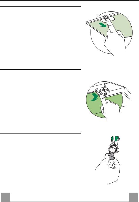
CLEANING METAL SELFSUPPORTING GREASE FILTERS
•The filters must be cleaned every 2 months of operation, or more frequently for particularly heavy usage, and can be washed in a dishwasher.
•Remove the filters one at a time by pushing them towards the back of the group and pulling down at the same time.
•Wash the filters, taking care not to bend them. Allow them to dry before refitting.
•When refitting the filters, make sure that the handle is visible on the outside.
Activated charcoal filter (Recirculation version)
REPLACING THE ACTIVATED CHARCOAL FILTER
•The filter is not washable and cannot be regenerated, and must be replaced approximately every 4 months of operation, or more frequently for particularly heavy usage.
•Remove the metal grease filters.
•Remove the saturated activated carbon filter by releasing the fixing hooks.
•Fit the new filter by hooking it into its seating.
•Refit the metal grease filters.
Lighting
LIGHT REPLACEMENT
20 W halogen light.
•Remove the 2 screws fixing the Lighting support, and pull it out of from the Hood.
•Extract the lamp from the Support.
•Replace with another of the same type, making sure that the two pins are properly inserted in the lamp holder socket holes.
•Refit the Support, fixing it in place with the two screws removed as above.
EN
9
9

EASY CLEANING TM
Removing the Grease Filters
Before carrying out Maintenance on the EASY CLEANING Suction Unit:
• Disconnect the hood by switching off the
twopole switch on the mains power supply |
A |
|
line, or by switching off the main power |
||
|
||
switch. |
|
•Remove the grease filters from the hood.
•If the hood is of the recirculation type, remove the odour filters:
• |
For hoods with a flat cartridge (A): turn the |
|
• |
fastening elements provided; |
B |
For hoods with a bayonet cartridge (B): |
|
|
|
turn as indicated and extract. |
|
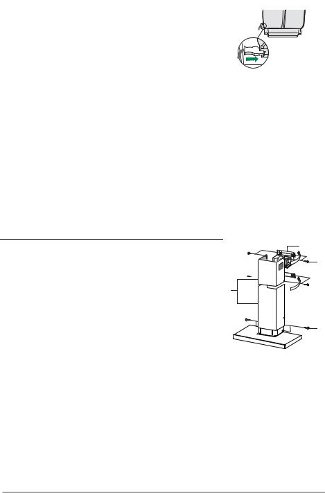
Disconnecting the EASY CLEANING Suction Unit
•Disconnect the power connector Ca and the control and lighting connector Cmd on the sides of the unit.
•For wall-mounted hoods and free-standing hoods with square chimney, turn the levers Lb locking the suction unit, so that they disconnect from the pins.
•For free-standing hoods with round chimney, unscrew the plugs Vb locking the suction unit.
•Pull the suction unit forwards so that it unhooks from the support pins, and remove it downwards through the air outlet.
Ca |
Cmd |
Lb
 Vb
Vb
EN |
|
1 |
|
10 |
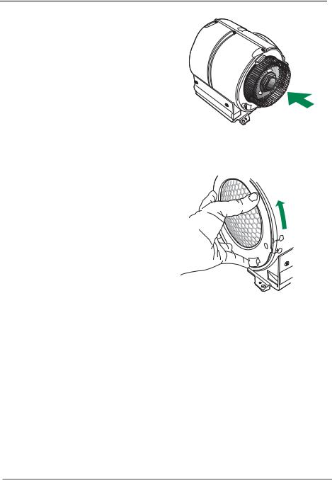
Dismantling Washable Parts
• To remove the side grilles protecting the fans, lift up the stop tooth using a knife or screwdriver and turn the grilles in the direction indicated by the arrow.
LOCK |
O |
P |
|
|
E |
|
N |
FREE |
|
•Grasp the fans in the holes provided and pull to extract.
CLEANING
•Wash the fans and the protection grilles, using normal washing-up liquid. These elements can also be washed in the dishwasher.
•Using a damp cloth and a suitable detergent, clean the body of the suction device, taking great care not to allow any water to leak into the inside of the unit or into the connector housings.
•Leave until completely dry bifore reassembling.
•Using a brush, clean the air outlet pipe as far as you can reach.
EN
1
11
REASSEMBLY
N.B. To avoid reassembling the wrong way round, the two fans have different couplings.
•Reassemble the fans on the corresponding pins, pressing them until they snap into place.
•Fit the protection grilles so that the teeth coincide in the “FREE” position and when turned to “LOCK”.
•Replace the EASY CLEANING suction unit on the hood, inserting it in position and connecting it to the support pins.
•Turn the lock levers, or screw in the lock plugs.
•Connect the power connector and the command connector to the sockets on the sides of the suction device.
•Replace any activated charcoal odour filters.
•Replace the grease filters.
•Connect the hood to the power supply system, by turning the two-pole switch on the mains power line to on, or by turning the main switch on.
•Check that the hood is working properly, by turning the motor and lighting on.
O P E N
LOCK
FREE
EN |
|
1 |
|
12 |
RÅD OG ANVISNINGER
 Denne brugervejledning gælder for flere versioner af apparatet.
Der fremstilles muligvis enkelte dele af tilbehøret, der ikke vedrører jeres apparat.
INSTALLATION
•Producenten kan ikke holdes ansvarlig for eventuelle skader, der skyldes ukorrekt eller forkert installation.
•Den mindst tilladelige sikkerhedsafstand mellem komfurets top og emhættens underside er 650 mm (nogle modeller kan installeres lavere, jævnfør afsnittene vedrørende ydre mål og installation).
•Kontrollér, at lysnetspændingen er den samme som den spænding, der er angivet mærkepladen, der sidder på inde i emhætten.
•For Klasse I apparater skal det også kontrolleres, at elforsyningen er forsynet med jord.
•Emhætten kobles til aftrækskanalen ved hjælp af et rør med en min.-diameter på 120 mm. Afstanden fra emhætten til kanalen skal være så kort som mulig.
•Emhætten må ikke tilsluttes en kanal, der fører forbrændingsgasser ud i det fri (oliefyr, brændeovne etc.).
•Hvis emhætten skal anvendes i forbindelse med ikke-elektriske apparater (f.eks. gaskomfur, gaskogeblus), skal det sikres, at lufttilgangen til rummet er tilstrækkelig, så aftræksgasserne ikke slår tilbage. Køkkenet skal have en åbning, der har direkte forbindelse til det fri, så der er sikret en tilstrækkelig mængde ren luft.
ANVENDELSE
• Emhætten er udelukkende beregnet til at fjerne em og lugte i køkkener i private husholdninger.
• Emhætten må kun anvendes til det formål, hvortil den er konstrueret. |
|
|
|
|
|
|
|
|
||
• Der må ikke forekomme høj åben ild under emhætten, mens den anvendes. |
|
|
|
|
|
|
|
|
||
|
|
|
|
|
|
|
|
|||
• Justér brænderen, så flammerne er rettet direkte mod bunden af panden/gryden – de |
|
|
|
|
|
|
|
|
||
|
|
650 mm min. |
|
|||||||
må ikke nå ud over kanten af bunden. |
|
|
|
|||||||
|
|
|
|
|
|
|
|
|||
• Frituregryder skal under brug holdes under konstant opsyn: kogende varm olie kan |
|
|
|
|
|
|
|
|
|
|
|
|
|
|
|
|
|
|
|
|
|
|
|
|
|
|
|
|
|
|
|
|
sprøjte ind i flammerne. |
|
|
|
|
|
|
|
|
||
•Emhætten må ikke anvendes af børn og personer, som ikke ved, hvordan den betjenes.
•Apparatet er ikke beregnet til at skulle anvendes af mindre børn eller svækkede personer uden opsyn.
•Undlad at flambere retter under emhætten; der opstår ellers brandfare.
•Dette apparat må ikke anvendes af personer (derunder børn) med nedsatte psykiske, sensoriske eller sindsmæssige evner, eller personer uden erfaring eller tilstrækkeligt kendskab, med mindre de overvåges eller oplæres i brug af apparatet af personer, der er ansvarlige for deres sikkerhed.
• Børn skal overvåges for at undgå, at de leger med apparatet.
VEDLIGEHOLDELSE
• Inden apparatet skal vedligeholdes eller rengøres, skal der slukkes for det eller stikket skal tages ud af stikkontakten.
•Rengør og/eller udskift filtrene iht. det angivne tidinterval (Brandbare).
•Rengør emhætten ved hjælp af en fugtig klud og et neutralt flydende rengøringsmiddel.
Symbolet  på produktet eller på pakken angiver, at dette produkt ikke må behandles som husholdningsaffald. Det skal i stedet overgives til en affaldsstation for behandling af elektrisk og elektronisk udstyr. Ved at sørge for at dette produkt bliver bortskaffet på den rette måde, hjælper du med til at forebygge eventuelle negative påvirkninger af miljøet og af personers helbred, der ellers kunne forårsages af forkert bortskaffelse af dette produkt. Kontakt det lokale kommunekontor, affaldsselskab eller den forretning, hvor produkt er købt, for yderligere oplysninger om genanvendelse af dette produkt.
DK |
|
1 |
|
13 |
APPARATBESKRIVELSE
|
Dimensioner |
|
|
|
|
|
64 |
42 |
|
|
|
|
|
|
|
940 |
|
|
|
540 |
680 |
|
|
|
60 |
|
|
|
|
|
898 |
|
Min. |
Min. |
|
300 |
|
||
|
|
650mm |
650mm |
|
|
|
|
||
|
150 |
|
|
|
108 |
260 |
|
|
|
490 |
|
|
|
|
Komponenter
Ref. Stk. Produktets komponenter
11 Emhættens hoveddel inkl.: Betjeningsanordninger, lys, ventilatorenhed, filtre
2 |
1 |
Teleskopaftræk bestående af: |
2.1 |
1 |
Øverste aftræk |
2.2 |
1 |
Nederste aftræk |
9 |
1 |
Passtykke ø 150-120 mm |
10 |
1 |
Sidestykke med ventil |
14.1 |
2 |
Forlænger til luftudstrømnings overgangsstykke |
15 |
1 |
Luftudstrømnings overgangsstykke |
|
|
|
Ref. |
Stk. |
Installationsdele |
7.2.1 |
2 |
Beslag til befæstigelse af øverste aftræk |
7.3 |
1 |
Støttebeslag til overgangsstykket |
11 |
6 |
Forankringer |
12a |
6 |
Skruer 4,2 x 44,4 |
12c |
6 |
Skruer 2,9 x 9,5 |
|
|
|
|
Stk. |
Dokumentation |
|
1 |
Brugerhåndbog |
15
14.1
7.3 |
12a |
7.2.1 |
11 |
|
9
10
2.1 |
12c |
|
2
2.2
11 |
12a |
1
DK |
|
1 |
|
14 |
INSTALLATION
Boring i væg og befæstigelse af beslag
7.37.2.1
X 1÷2
11 |
116 |
116 |
12a |
|
|
650 min.
320
På væggen skal der afmærkes:
•en lodret linje op til loftet eller den øverste grænse, i midten af emhættens monteringsområde;
•en vandret linje mindst 650 mm over kogepladen.
•Placér beslaget 7.2.1 som vist, d.v.s. 1-2 mm fra loftet eller den øverste grænse, og stil dets midte (indskæringer) på lige linje med den lodrette referencelinje.
•Afmærk midten af hullerne i beslaget.
•Placér beslaget 7.2.1 som vist, X mm under det første beslag (X=højden på det øverste aftræk, der følger med), og stil dets midte (indskæringer) på lige linje med den lodrette referencelinje.
•Afmærk midten af hullerne i beslaget.
•Afmærk som vist en reference 116 mm fra den lodrette referencelinje, 320 mm over den vandrette referencelinje.
•Gør det samme på den anden side.
•Bor et hul med ø 8 mm på de afmærkede steder.
•Sæt forankringerne 11 i hullerne.
•Fastgør det nederste beslag 7.2.1 ved hjælp af de medfølgende skruer 12a (4,2 x 44,4 ).
•Fastgør det øverste beslag 7.2.1 og overgangsstykkets støttebeslag 7.3 ved hjælp af de 2 medfølgende skruer 12a (4,2 x 44,4).
•Skru de 2 medfølgende skruer 12a (4,2 x 44,4) fast i hullerne til fastgøring af emhættens hoveddel, hvorved der skal sikres en afstand på 5-6 mm mellem væggen og skruens hoved.
DK |
|
1 |
|
15 |
Montering af emhætte |
|
|
• Inden man hænger emhætten op, skal man stramme de to skru- |
|
Vr |
er Vr, som sidder i hættens ophængningspunkter. |
|
|
|
|
|
• Hæng emhætten op på de forberedte skruer 12a. |
|
|
• Stram ophængningsskruerne 12a helt til. |
|
|
• Ved at dreje på skruerne Vr nivelleres emhætten. |
12a |
|
Tilslutninger |
|
|
VERSION FORBUNDET TIL AFTRÆKSKANAL |
|
|
Når aftrækskanal-versionen opsættes, forbindes emhætteenheden |
|
|
til kanalen med en flexslange eller et hårdt rør, Ø150 eller 120 |
|
|
mm – valget er op til den, der opsætter emhætten. |
ø 150 |
ø 120 |
Tilslutning af rør på ø 150 |
10 |
9 |
• Indsæt studsen på ø 150 10 på emhættens udsugningshul. |
|
10 |
• Spænd røret fast med specielle rørklemmer. Disse medleveres |
|
|
ikke. |
|
|
Tilslutning af rør på ø 120
•Ved tilslutning af rør på ø120 mm, indsættes reduktionsstudsen 9 på studsen ø 150, som er monteret tidligere.
•Spænd røret fast med specielle rørklemmer. Disse medleveres ikke.
•I begge tilfælde skal man fjerne eventuelle lugtabsorberende kulfiltre.
LUFTUDSTRØMNING PÅ FILTRERENDE VERSION
•Før overgangsstykkets forlængere 14.1 ind på siden af overgangsstykket 15.
•Før overgangsstykket 15 ind i støttebeslaget 7.3, og spær det fast med en skrue.
•Sørg for at udgangen på overgangsstykkets forlængere 14.1 befinder sig ud for aftrækkets mundinger, både vandret og lodret.
•Forbind overgangsstykket 15 til emhættens hoveddels udgang ved hjælp af et rør eller en flexslange med ø150, som det påhviler installatøren at vælge.
•Sørg for, at lugtfiltret med aktivt kul er monteret.
7.3 |
14.1 |
|
|
15 |
|
|
ø 150 |
DK |
|
1 |
|
16 |
TILSLUTNING TIL STRØMFORSYNING
•Tilslut emhætten til elnettet, idet der indsættes en topolet afbryder med en kontaktafstand på mindst 3 mm.
•Fjern fedtfiltrene (se afsnittet ”Vedligeholdelse”) og kontroller, at eltilslutningens kabelklemme er korrekt indsat i udsugningsgruppens stik.
Montering af aftræk
Øverste aftræk
•Skub de to sideflapper lidt ud, sæt dem fast bag ved beslagene 7.2.1, og luk dem til igen, helt til stoppet.
•Fastgør dem på siden af beslagene ved hjælp af de 4 medfølgende skruer 12c (2,9 x 9,5 ).
•Sørg for at udgangen på overgangsstykkets forlængere befinder sig ud for aftrækkets mundinger.
Nederste aftræk
•Skub aftrækkets sideflapper lidt ud, sæt dem fast mellem det øverste aftræk og væggen, og luk dem igen, helt til stoppet.
•Fastgør undersiden på siden af emhættens hoveddel ved hjælp af de 2 medfølgende skruer 12c (2,9 x 9,5 ).
7.2.1
12c |
2.1 
 2
2 
2.2
12c
DK |
|
1 |
|
17 |
 Loading...