

Optional Accessories
for the P-DP30 Drill Press:
Micro Chuck (A-MC2)– An accurate,
economical adapter chuck, used for 60 to 80
wire gauge drills. The A-MC2 can be held in
″ or 3/16″ collet.
any 1/8
Hardened Tool Steel Step Drills – Drill point
sizes from .5mm (#76) to 2.3mm (#43).
Refer to the Foredom Accessory Catalog for
a complete listing of sizes. All have 3/ 32
diameter shanks.
Chuck Key Handle (HPCK-0)– For H.30®,
H.25C and H.30H Handpieces. Comes with
#0 chuck key in handle.
″
For More Information
For more information on Foredom machines,
handpieces, and accessories, contact your
local dealer. When no local dealer is available,
visit www.foredom.com on the web.
The Foredom Electric Company
16 Stony Hill Road, Bethel, CT 06801
Tel.: 203-792-8622 • Fax: 203-796-7861
LIMITED WARRANTY
The Foredom Electric Company warrants the P-DP30 Drill Press to be free of defects in
material or workmanship for a period of one year after purchase. During the warranty
period, the defective product will be repaired or replaced without charge or, at our option,
the purchase price will be refunded. This warranty does not cover damage caused in transit
or by accident, misuse, or ordinary wear.
ALL IMPLIED WARRANTIES, INCLUDING BUT NOT LIMITED TO WARRANTIES OF FITNESS
AND MERCHANTABILITY, ARE HEREBY LIMITED IN DURATION TO A PERIOD ENDING ONE
YEAR FROM DATE OF PURCHASE, AND WE WILL NOT BE LIABLE OR RESPONSIBLE FOR
ANY SPECIAL OR CONSEQUENTIAL DAMAGES.
FOREDOM
®
P-DP30
Drill Press
Owner’s
Manual
®
Repair or replacement will be made at our option if the product is returned
post-paid to:
The Foredom Electric Company
16 Stony Hill Road
Bethel, CT USA 06801
All warranty repairs must be done at the factory at the above address. We will not pay any shipping or
transportation charges. This warranty only covers the original purchaser of the product. Some states
do not allow limitations on how long an implied warranty lasts, so the above limitations may not apply
to you. This warranty gives you specific legal rights, and you may also have other rights which vary
from state to state.
®
FOREDOM
he Foredom Electric Company
T
Bethel, CT USA 06801
www.foredom.com
Form 1242 n 12/09
Printed in USA
For Your Own Safety:
Always wear eye protection.
Read this Owner’s Manual
before operating your
Foredom tool.

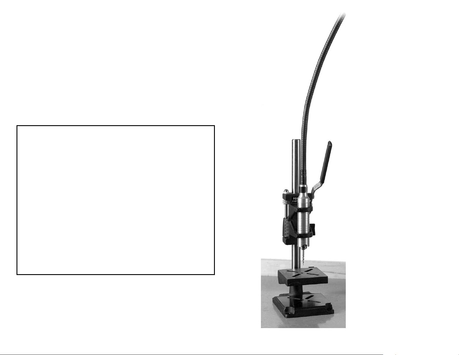
General Information
The Foredom®P-DP30 Drill Press is designed
for use with the H.30
H.44HT handpieces. It securely holds the
handpiece in a vertical position for drilling
straight, accurate holes to specified depths.
In addition to drilling, it is ideal for modeling,
spot-facing, countersinking and reaming in
wood, wax, plastic, metal, glass and gemstone.
®
, H.30H, H.44T and
Please follow these
important safety instructions:
Always wear safety glasses to protect eyes
from flying debris and chips.
Never continue to use a drill or accessory
which appears to be wobbling, out of round,
vibrating or not running true.
Always use drills and accessories rated for
18,000 RPM or higher.
Never wear loose clothing, dangling jewelry or
other apparel which may become caught in
the equipment.
Always keep hands, fingers and hair well away
from the drill or other accessories.
Always bolt down the Drill Press for
extra stability.
Set-Up and Operation
As you unpack the Drill Press, make sure that
you have the complete assembly (see illustration) and the 7/64
Loosen the Adjusting Knob and move the Head
Assembly up the Post to the desired height.
Tighten the Knob securely. Be sure
that the head, table and base are aligned
and centered.
Foredom recommends bolting the drill press
to the workbench or platform for extra
stability.
the four holes provided in the Base Plate.
Fasten to the workbench or to a piece of
plywood approximately 2
Arm Adjustment
est the downstroke action of the handle. This
T
has been preadjusted at the factor
have rattled loose during shipping. It should
″ Allen wrench provided.
Insert suitable length bolts through
′ x 2′ x 3⁄4″.
, but may
y
feel smooth and free. If it feels too loose,adjust
the Shoulder Screwsin the handle arm assembly.These screws should be tightened snugly.
Inserting the Handpiece
Do not tighten cap screws unless handpiece
is inserted in holder.
loosen the two Socket Cap Screws with the
supplied Allen Wrench. Insert the handpiece
into the Handpiece Guides. When using the
®
or H.30H Handpiece, make sure the
H.30
chuck key hole is facing forward and is accessible. If using the H.44T or H.44HT Handpiece,
make sure that the pin hole is accessible.
Insert the handpiece through both guides until
the tip of the collet or chuck is approximately
1″ below the bottom guide. Tighten alternately
the two Socket Cap Screws enough to prevent
the handpiece from turning in the guides. Next,
insert the drill or accessory and tighten securely in the chuck or collet using the chuck key for
the H.30
wrench for the H.44T or H.44HT.
Be sure to remove the pin from the handpiece
hole of the H.44T or H.44HT before starting
the motor.
Table Adjustment
Determine the desired table height for the
thickness of the material to be worked. When
using a drill, make sure that the drill tip is
aligned with the
by moving the drill gently through the hole
while the motor is still off.
Removing Adjustable Table
If you need to remove the adjustable table,
the Handpiece Head Assembly must be
removed first. Loosen the Head Adjusting Knob
and slide the Head Assembly up and off the
Post.
on the Head Assembly before loosening the
knob. It could be damaged if allowed to drop.
Place the head on the work surface, handle
side up. Repeat procedure with the Adjustable
Table. Replace the Handpiece Head Assembly
onto the post and tighten the Adjusting Knob,
aligning head and base plate.
®
or H.30H handpiece and the pin and
Note: Make sure that you have a firm grip
To insert the handpiece,
center of the Table Drill Hole
Drill Stroke Adjustment
Adjust the drill stroke depth from (0–11⁄4″)
with Lock Nuts. Move the Depth Stroke
Indicator to the desired measurement on
the Scale by pressing down on the
handle. Hold at desired setting and move Lock Nuts
until the depth
indicator is stopped.
Securing the
Workpiece
Slots are provided in the
Adjustable Table and
Base Plate for use with
clamps, jigs, and other
holding devices. Make sure
the workpiece is securely
fastened before
beginning work.
Drilling
For drilling, generally high-speed
steel, carbide and diamond drills
are most often used. Whatever
accessory you use,
the tool do the work.
pressure can damage or break your drill, and
may cause loss of control.
used for drilling holes in metals, woods, and
plastics. On work items with rounded surfaces
such as rods, it is a good idea to centerpunch a
starting hole to keep the tip of the drill from
“walking” or wandering from the desired
starting point.
When drilling, lift the drill up and down
frequently to clear away dust and chips.
Speed
Always use drills and accessories rated for
18,000 RPM or higher
determined by experience and varies with the
type of material being drilled, the type of drill or
accessory, the thickness of the material, and the
type of work being done. Follow recommendations of the drill or accessor
Usually, higher speeds are used on soft
materials and lower speeds on harder materials.
It is always a good idea to experiment on a
let the speed of
Too much feeding
Twist drills are often
. Generally, work speed is
y manufacturer
.
scrap piece of material before beginning the
final work operation.
Coolants
Coolants are sometimes needed to help keep
the accessory cool and to keep the workpiece
clean of debris. Which type to use is determined by the material and the accessory and
will vary with operator preference. Wetting
agents with rust inhibitors, waxes, oils and
water are often used when drilling very hard
materials such as metals, gems and stones.
Lubrication
All unpainted sur
inhibitor when shipped. Be sure to clean away
all debris after use. Respray with rust inhibitor
when necessary, especially during storage. The
Spring and two Shoulder Screws should be
lubricated periodically with a light coat of oil.
faces are sprayed with a rust
 Loading...