


 Loading...
INSTALLATION AND TECHNICAL
REFERENCE MANUAL
WARNING! REMOTE START SYSTEMS ARE ONLY APPLICABLE TO VEHICLES WITH AUTOMATIC TRANSMISSION!
BOTH ORIGINAL KEYS ARE REQUIRED FOR ALL REMOTE START SYSTEMS ON VEHICLES EQUIPPED WITH SECURILOCK!
EXPERT FITMENT REQUIRED Subject to Change Without Notice
ALL MODELS 2002 


Use Caution -
Personal Injury
Use Caution -
Vehicle Damage
Technical Support |
|
See shop manual |
(800) FORD-KEY |
|
|
|
|
|
For French Technical Support |
|
|
Rock Hebert (514) 973-2846 |
! |
Important note |
|
TOOLS REQUIRED
SILICONERUBBER
Silicone sealer
D6AZ-19562-AA
9/32”
8mm |
7mm 1/4” |
Super Seal |
|
|
F3AZ-19515-SA |
101871-2
1/42 |
2W7Z-16A901-AA |
SK5W7J-19A361-AA |
© Copyright Ford 2005 |
Rev Date- 8/29/05

TABLE OF CONTENTS |
|
READ ME FIRST ........................................................................................................... |
3 |
KIT CONTENTS ................................................................................................................................... |
4 |
PARTS BAG CONTENTS .................................................................................................................... |
5 |
KIT BILL OF MATERIALS LISTS ........................................................................................................ |
6 |
MODULE PREPARATION ................................................................................................................... |
9 |
VEHICLE PREPARATION ................................................................................................................. |
11 |
DIPOLE ANTENNA MOUNTING ....................................................................................................... |
12 |
STATUS LED ..................................................................................................................................... |
13 |
SECURILOCK INTERFACE KITS - 1L2Z-19G365-AB & 1S4Z-19G365-AB .................................... |
14 |
SECURILOCK INTERFACE KIT - 1L3Z-19G365-AB ....................................................................... |
17 |
SIREN INSTALLATION ..................................................................................................................... |
18 |
HOOD TILT SWITCH INSTALLATION .............................................................................................. |
19 |
MOUNTING THE CONTROL MODULE ............................................................................................ |
20 |
SYSTEM WIRING CONNECTIONS................................................................................................... |
21 |
WARNING LABEL INSTALLATION .................................................................................................. |
21 |
SYSTEM PROGRAMMING INSTRUCTIONS.................................................................................... |
22 |
TRANSMITTER PROGRAMMING: .............................................................................................. |
22 |
OPTION PROGRAMMING: .......................................................................................................... |
22 |
SHOCK SENSOR SETTING ........................................................................................................ |
23 |
TACH (IDLE SPEED) PROGRAMMING ...................................................................................... |
24 |
REFERENCE SECTION ............................................................................................ |
26 |
SECURILOCK INTERFACE AND RELAY APPLICATION CHART .................................................. |
26 |
OPTION PROGRAMMING CHARTS ................................................................................................. |
29 |
RKE/VSS/RMST OPTION CHART .............................................................................................. |
29 |
RKE/RMST OPTION CHART....................................................................................................... |
31 |
RMST OPTION CHART ............................................................................................................... |
33 |
DELUXE RKE/VSS OPTION CHART.......................................................................................... |
34 |
RKE/VSS & VSS OPTION CHART.............................................................................................. |
35 |
RKE OPTION CHART .................................................................................................................. |
36 |
LOT MODE ONLY OPTION CHART ............................................................................................ |
37 |
WIRING HARNESS LEGEND ........................................................................................................... |
38 |
CIRCUIT TESTING - IDENTIFYING CIRCUIT POLARITY ................................................................ |
39 |
WIRE CONNECTION PROCEDURES.............................................................................................. |
40 |
VEHICLE SPECIFIC WIRING DIAGRAMS ............................................................... |
42 |
2/42 |
2W7Z-16A901-AA |
SK5W7J-19A361-AA |
© Copyright Ford 2005 |
Rev Date- 8/29/05

READ ME FIRST
For convenience this document uses short names when referring to a particular system or kit. The list below identifies the short names used herein:
Remote Start System with Deluxe Vehicle Security and Keyless Entry —> RKE/VSS/RMST Remote Start System with Keyless Entry —> RKE/RMST
Remote Start System —> RMST
Deluxe Vehicle Security System with Keyless Entry —> Deluxe RKE/VSS Vehicle Security System with Keyless Entry —> RKE/VSS
Vehicle Security System for Vehicles Equipped with Factory Keyless Entry —> VSS Keyless Entry System —> RKE
Navigating this document can be accomplished by: 1) using the buttons in the Acrobat toolbar, 2) clicking on the bookmark links in the bookmark pane to the left. (Clicking on the (+) symbols next to a bookmark will expand that bookmark, revealing additional selections) or 3) clicking on a topic in the table of contents located on page 2.
The most current version of this document can be accessed at www.mcdistributor.com and/or www.fmcdealer.com. As new/ updated material becomes available, this document will be updated and posted on those sites.
This installation instruction covers the installation of all PowerCode based Convenience/Security and Remote start kits, therefore follow only the steps that apply to the kit that you are installing. For example, the Securilock interface kits are only used on systems that include remote start (RMST). Therefore, if you are installing a security only kit, skip the steps pertaining to the Securilock interface kit.
Vehicle wiring is subject to change. All possible efforts have been taken to ensure that the information contained herein is accurate as of the revision dates indicated. As such, it is critical that vehicle circuits are tested prior to making any connections, to ensure that the proper vehicle circuit has been located.
Prior to beginning this installation it is recommended that you lower the drivers door window to prevent locking the keys in the vehicle.
The installation instructions are presented in three sections. The first section (which begins immediately following this page) contains installation instructions for the systems various components and tips for prepping the systems wiring harnesses. These steps are presented in a generic format. The procedures for these installation steps are basically the same regardless of the model vehicle or system that you are working on. The drawings depicted in this section are for reference only and may not reflect the vehicle on which you may be working.
The second (reference) section contains the system option programming charts and various other reference type information. The last section presents vehicle specific wiring diagrams for each application. Within the wiring section for each vehicle, there are separate wiring diagrams for each different system. The vehicle specific wiring drawings are arranged in the following order:
1.RKE/VSS/RMST & RKE/RMST (in the same drawing) - Typically 4 pages;
2.RMST - 1 page
3.Deluxe RKE/VSS - 3 - 4 pages;
4.RKE/VSS & RKE installation options - 1 page;
5.VSS - Typically 1 page;
6.Pre-load system wiring - 1 page;
7.Fuse placement and vehicle specific programming requirements - 1 page.
Vehicles that are equipped with 100% factory keyless entry will not have the RKE/VSS & RKE drawing. Some drawings will have blank pages inserted to maintain the page order.
Prior to beginning your first installation of this product it is recommended that you:
1.Thoroughly review and print out the first section;
2.Skim through the reference section to become acquainted with the additional information that is available.
Then, when going through the installation print out the vehicle specific wiring section and use as a reference during the installation.
3/42 |
2W7Z-16A901-AA |
SK5W7J-19A361-AA |
© Copyright Ford 2005 |
Rev Date- 8/29/05
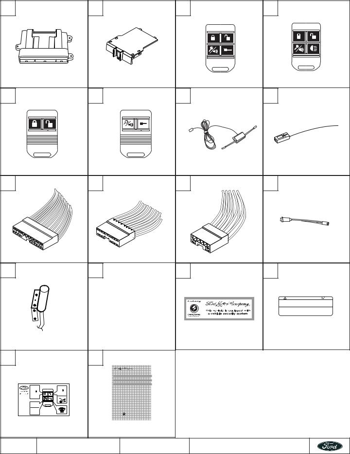
KIT CONTENTS |
|
|
|
|
|
|
A |
|
B |
|
C |
|
D |
PC-12 - 2W7J-19A498-AA |
|
SEE KIT BOM |
|
2W7J-15K601-BA |
2W7J-15K601-BA |
|
EPC-32 - 2W7J-19G367-AA |
|
|
||||
F |
|
G |
|
H |
||
2W7J-15K601-AA |
|
2W7J-15K601-AA |
|
2W7J15603-AA |
N/A |
|
I |
|
J |
|
K |
|
L |
M 2W7J-19A205-AA |
N |
2W7J-19A206-AA |
O |
2W7-J12060-AA |
P N/A |
|
|
|
|
|
|
|
WARNING: / AVERTISSEMENT |
|
|
|
|
|
|
This vehicle is equipped with a remote controlled engine starter. |
|
|
|
|
|
|
To reduce the risk of serious Injury or death, switch engine starter |
|
|
|
|
|
|
system into service mode and disconnect the vehicle battery |
|
|
|
|
|
|
before performing any service on the vehicle. |
|
|
|
|
|
|
Ce véhicule est doté d'un démarreur à distance. Pour réduire les |
|
|
|
|
|
|
risques de blessures graves ou mortelles, mettre le démarreur à |
|
|
|
|
|
|
distance en mode service et débrancher la batterie du véhicule |
|
|
|
|
|
|
avant d'effectuer des travaux d'entretien sur celui-ci. |
2W7J-19G366-AA |
|
2W7J-15W593-AA |
|
N/A |
N/A |
|
Q |
|
R |
|
|
|
|
|
|
|
Vehicle Security and Remote Start Systems |
|
|
|
|
|
|
Remote Start System with Deluxe Vehicle Security |
|
|
|
|
|
|
Sistema de encendido por control remoto y seguridad para vehículos de lujo |
|
|
|
|
|
|
Système de démarrage à distance avec antivol de voiture de luxe |
|
|
|
|
|
|
Owner's Manual |
|
|
|
|
2 sec. |
|
Manual del propietario |
|
|
|
|
|
|
Guide de l’utilisateur |
|
|
|
|
5X |
|
|
|
|
|
|
2 sec. |
|
|
|
|
|
|
30 |
|
|
|
|
|
|
sec. |
|
Featuring PowerCode Technology |
|
|
|
|
|
|
For the Ultimate in Comfort, Convenience and Security |
|
|
|
|
N/A |
|
N/A |
|
|
|
4/42 |
2W7Z-16A901-AA |
SK5W7J-19A361-AA |
© Copyright Ford 2005 |
|||
Rev Date- 8/29/05
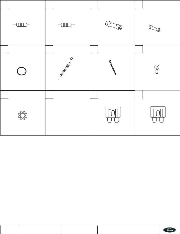
PARTS BAG CONTENTS |
|
|
|
|
|
S |
T |
|
U |
|
V |
|
750 OHM |
1800 OHM |
|
|
|
|
1X |
1X |
|
2X |
6X |
W |
X |
Y |
|
Z |
|
|
2X |
5X |
|
10X |
1X |
AA |
BB |
|
CC |
|
DD |
|
|
|
5A |
|
15A |
|
2X |
7X |
|
1X |
PC-12 - 4X |
|
|
PC-32 - 7X |
|||
NOTE: Part bag contents are not available as service items
5/42 |
2W7Z-16A901-AA |
SK5W7J-19A361-AA |
© Copyright Ford 2005 |
Rev Date- 8/29/05

KIT BILL OF MATERIALS LISTS 2W7Z-19G364-AA
Remote Start System w/Deluxe Vehicle Security and Keyless Entry Kit (RKE/VSS/RMST)
REF |
DESCRIPTION |
QTY |
A |
PC-32 MODULE ASSEMBLY |
1 |
B |
RKE/VSS/RMST DNA ASSEMBLY (2W7J-19G367-BA) |
1 |
C |
4 BUTTON POWERCODE TRANSMITTER W/REMOTE START ICONS |
2 |
I |
24-WAY WIRING HARNESS (BASE) |
1 |
J |
16-WAY WIRING HARNESS (ADVANCE FUNCTIONS) |
1 |
K |
10-WAY WIRING HARNESS (CAR START FUNCTIONS) |
1 |
L |
STATUS INDICATOR ASSEMBLY |
1 |
G |
DIPOLE ANTENNA |
1 |
M |
HOOD SAFETY SWITCH ASSEMBLY |
1 |
N |
125 DB SIREN ASSEMBLY |
1 |
S - BB |
INSTALLATION PARTS BAG |
1 |
CC, DD |
FUSE PARTS BAG |
1 |
R |
OPERATORS INSTRUCTION |
1 |
S |
OPERATORS QUICK REFERENCE WALLET CARD |
1 |
O |
VSS WINDOW WARNING DECAL |
2 |
P |
UNDERHOOD WARNING LABEL |
1 |
2W7Z-19G364-BA
Remote Start System w/Keyless Entry Kit (RKE/RMST)
REF |
DESCRIPTION |
QTY |
A |
PC-32 MODULE ASSEMBLY |
1 |
B |
RKE/RMST DNA ASSEMBLY (2W7J-19G367-DA) |
1 |
C |
4 BUTTON POWERCODE TRANSMITTER W/REMOTE START ICONS |
2 |
I |
24-WAY WIRING HARNESS (BASE) |
1 |
J |
16-WAY WIRING HARNESS (ADVANCE FUNCTIONS) |
1 |
K |
10-WAY WIRING HARNESS (CAR START FUNCTIONS) |
1 |
L |
STATUS INDICATOR ASSEMBLY |
1 |
G |
DIPOLE ANTENNA |
1 |
M |
HOOD SAFETY SWITCH ASSEMBLY |
1 |
S - BB |
INSTALLATION PARTS BAG |
1 |
CC, DD |
FUSE PARTS BAG |
1 |
R |
OPERATORS INSTRUCTION |
1 |
S |
OPERATORS QUICK REFERENCE WALLET CARD |
1 |
P |
UNDERHOOD WARNING LABEL |
1 |
6/42 |
2W7Z-16A901-AA |
SK5W7J-19A361-AA |
© Copyright Ford 2005 |
Rev Date- 8/29/05

2W7Z-19G364-CA
Remote Start System Kit (RMST)
REF |
DESCRIPTION |
QTY |
A |
PC-32 MODULE ASSEMBLY |
1 |
B |
RMST DNA ASSEMBLY (2W7J-19G367-CA) |
1 |
F |
2 BUTTON POWERCODE TRANSMITTER W/REMOTE START ICON |
2 |
I |
24-WAY WIRING HARNESS (BASE) |
1 |
K |
10-WAY WIRING HARNESS (CAR START FUNCTIONS) |
1 |
L |
STATUS INDICATOR ASSEMBLY |
1 |
G |
DIPOLE ANTENNA |
1 |
M |
HOOD SAFETY SWITCH ASSEMBLY |
1 |
S - BB |
INSTALLATION PARTS BAG |
1 |
CC, DD |
FUSE PARTS BAG |
1 |
R |
OPERATORS INSTRUCTION |
1 |
S |
OPERATORS QUICK REFERENCE WALLET CARD |
1 |
P |
UNDERHOOD WARNING LABEL |
1 |
2W7Z-19A361-DA
Deluxe Vehicle Security and Keyless Entry Kit (Deluxe RKE/VSS)
REF |
DESCRIPTION |
QTY |
A |
PC-12 MODULE ASSEMBLY |
1 |
B |
Deluxe RKE/VSS DNA ASSEMBLY (2W7J-19A498-DA) |
1 |
D |
4 BUTTON POWERCODE TRANSMITTER W/HEADLIGHT ICONS |
2 |
I |
24-WAY WIRING HARNESS (BASE) |
1 |
J |
16-WAY WIRING HARNESS (ADVANCE FUNCTIONS) |
1 |
L |
STATUS INDICATOR ASSEMBLY |
1 |
G |
DIPOLE ANTENNA |
1 |
N |
125 DB SIREN ASSEMBLY |
1 |
S - BB |
INSTALLATION PARTS BAG |
1 |
CC, DD |
FUSE PARTS BAG |
1 |
R |
OPERATORS INSTRUCTION |
1 |
S |
OPERATORS QUICK REFERENCE WALLET CARD |
1 |
O |
VSS WINDOW WARNING DECAL |
2 |
7/42 |
2W7Z-16A901-AA |
SK5W7J-19A361-AA |
© Copyright Ford 2005 |
Rev Date- 8/29/05

2W7Z-19A361-CA
Vehicle Security and Keyless Entry Kit (RKE/VSS)
REF |
DESCRIPTION |
QTY |
A |
PC-12 MODULE ASSEMBLY |
1 |
B |
RKE/VSS DNA ASSEMBLY (2W7J-19A498-CA) |
1 |
C |
2 BUTTON POWERCODE TRANSMITTER W/LOCK, UNLOCK ICONS |
2 |
I |
24-WAY WIRING HARNESS (BASE) |
1 |
L |
STATUS INDICATOR ASSEMBLY |
1 |
H |
WHIP ANTENNA |
1 |
S - BB |
INSTALLATION PARTS BAG |
1 |
CC, DD |
FUSE PARTS BAG |
1 |
R |
OPERATORS INSTRUCTION |
1 |
S |
OPERATORS QUICK REFERENCE WALLET CARD |
1 |
O |
VSS WINDOW WARNING DECAL |
2 |
2W7Z-19A361-BA
Vehicle Security Kit (VSS)
REF |
DESCRIPTION |
QTY |
A |
PC-12 MODULE ASSEMBLY |
1 |
B |
VSS DNA ASSEMBLY (2W7J-19A498-CA) |
1 |
I |
24-WAY WIRING HARNESS (BASE) |
1 |
L |
STATUS INDICATOR ASSEMBLY |
1 |
H |
WHIP ANTENNA |
1 |
S - BB |
INSTALLATION PARTS BAG |
1 |
CC, DD |
FUSE PARTS BAG |
1 |
R |
OPERATORS INSTRUCTION |
1 |
S |
OPERATORS QUICK REFERENCE WALLET CARD |
1 |
O |
VSS WINDOW WARNING DECAL |
2 |
2W7Z-19A361-AA
Keyless Entry Kit (RKE)
REF |
DESCRIPTION |
QTY |
A |
PC-12 MODULE ASSEMBLY |
1 |
B |
RKE DNA ASSEMBLY (2W7J-19A498-BA) |
1 |
I |
24-WAY WIRING HARNESS (BASE) |
1 |
L |
STATUS INDICATOR ASSEMBLY |
1 |
H |
WHIP ANTENNA |
1 |
S - BB |
INSTALLATION PARTS BAG |
1 |
CC, DD |
FUSE PARTS BAG |
1 |
R |
OPERATORS INSTRUCTION |
1 |
S |
OPERATORS QUICK REFERENCE WALLET CARD |
1 |
8/42 |
2W7Z-16A901-AA |
SK5W7J-19A361-AA |
© Copyright Ford 2005 |
Rev Date- 8/29/05

MODULE PREPARATION
1 Place the supplied fuses into the power distribution block on the control module. Refer to the fuse placement drawing for the specific vehicle that you are working on. Fuse placement drawings are located in vehicle specific wiring sections.
In this diagram, the parking light fuse is shown in the positive polarity position and the Dome light fuse is shown in the negative polarity position.
Note: The HVAC1, HVAC2 and IGNITION fuses are only used on systems including remote car start (requires PC-32 module).
DOME LIGHT |
|
|
|
|
|
|
PK LIGHTS |
|
|
|
|
|
|||
|
|
|
|
|
|
||
DRIVER DOOR UNLOCK/ |
|
|
|
|
|
DOOR LOCKS |
|
|
|
|
|
|
|||
TRUNK RELEASE |
|
|
|
|
|
|
|
|
|
|
|
|
|
|
|
|
|
|
+ |
|
15 |
+ |
15 |
15 |
15 |
- |
15 |
|
- |
|
|
|
15 |
|
|
|
15 |
15 |
15 |
5 |
|
|
|
|
|
|
15 |
15 |
15 |
5 |
|
|
|
HVAC 1 |
|
|
MAIN B+ |
|
|
|
HVAC 2 |
|
|
IGNITION |
|
|
2 |
Place the software cartridge (DNA) onto the control |
|
|
|
module as shown. |
3 |
Plug the wiring harness(es) into the module. |
|
|
|
|
Harness A: 24-way, used on all systems; |
|
|
|
|
Harness B: 10-way, used on all systems with car start; |
|
|
|
|
Harness C: 16-way, used on systems with convenience |
|
|
|
|
features (i.e. Headlight control, memory seat control) |
|
|
|
|
along with some preload system installations in vehicles |
|
|
|
|
without factory equipped RKE. |
|
|
|
|
If you are installing a system that uses the whip |
C |
A |
B |
|
|
|
|
|
|
antenna (RKE, RKE/VSS or Preload), plug the whip |
|
|
|
|
antenna into the module at this time. |
|
|
|
9/42 |
2W7Z-16A901-AA |
SK5W7J-19A361-AA |
© Copyright Ford 2005 |
Rev Date- 8/29/05
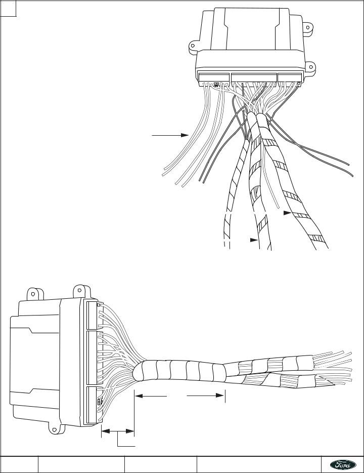
MODULE PREPARATION (Cont’t)
4 Referring to the vehicle specific wiring section for the system being installed, gather all individual wires that will be routed to the same areas of the vehicle into groups. Cover each wire group with tape for approximately 18”. Depending upon the vehicle, there will be 2 - 5 different wire groups.
Trim the unused wires approximately 6 - 8” from the module. Do not cut the override/programming button off of the harness, it is used for all installations.
Unused wires
|
Driver kick panel harness |
|
|
|
|
|
|
||
|
Steering column harness |
|
|
|
|
|
|||
|
|
|
|
|
5 |
Tape the harness sections together, making sure to cover all of the unused wires. |
|||
3” - 4”
2” - 3”
10/42 |
2W7Z-16A901-AA |
SK5W7J-19A361-AA |
© Copyright Ford 2005 |
Rev Date- 8/29/05
VEHICLE PREPARATION
1 A. To allow access to the necessary vehicle circuits, remove the interior panels as required.
B.Identify the control module mounting location and appropriate vehicle circuit connection points. Plan wire harness routings that will be free and clear of all moving underdash components (i.e. accelerator pedal, adjustable position brake pedal assembly and parking brake mechanism.
|
|
|
2 |
All models except LS, T-Bird, Escort, Econoline and |
|
|
Super-Duty Pick-ups, remove the steering column |
|
|
shroud to allow access to the PATS transceiver antenna |
|
|
|
|
|
ring around the ignition switch lock cylinder. |
|
|
|
|
3 |
Test for Factory Perimeter Alarm (vehicles equipped with factory RKE only): |
|
|
1. |
Roll down the driver’s door window and then close all doors, hood, trunk or hatch; |
|
2. |
Lock the doors using the factory RKE transmitter; |
|
3. |
Wait one minute, then reach in the driver door window and open the drivers door (do not unlock doors with the factory |
|
|
RKE remote). |
|
€ |
If the vehicle’s horn begins sounding when the door is opened, the vehicle is equipped with factory perimeter alarm. |
|
|
Unlock the doors with the factory RKE remote to turn off the alarm. In this case, wire the systems factory perimeter |
|
|
alarm disarm wire to the vehicle’s perimeter alarm disarm input (See the vehicle specific wiring section). Skip the test |
|
|
for door trim switch disable below. |
|
€ |
If the horn does not begin sounding when the door is opened, the vehicle is not equipped with factory installed |
|
|
perimeter alarm. Follow the test procedure below for door trim switch disable. |
Test for Door Trim Switch Disable option (vehicles equipped with factory RKE only): 1. Roll down the driver door window and close all doors, hood, trunk or hatch;
2. Lock the doors using the factory RKE transmitter;
3. Wait one minute, then reach in the driver door window and press the door trim unlock switch.
€If the doors unlock, the door trim disable feature is not enabled and no further action is required.
€If the doors do not unlock, connect the system’s factory alarm disarm output as shown in the vehicle specific wiring section or disable the door trim switch disable feature using the NGS or WDS testers.
11/42 |
2W7Z-16A901-AA |
SK5W7J-19A361-AA |
© Copyright Ford 2005 |
Rev Date- 8/29/05
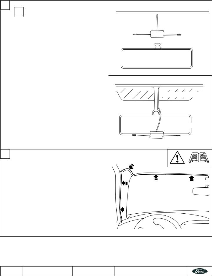
DIPOLE ANTENNA MOUNTING |
|
||
1 |
! |
The optimum operating range for this system is |
|
|
dependant upon proper selection of the mounting |
|
|
|
|
location for the Dipole antenna. |
|
|
• |
Never mount the antenna behind (or on) any metal |
|
|
|
film or metal film window tint on the windshield. |
|
|
• |
Never mount the antenna so that one of the antenna |
|
|
|
elements touches or crosses any vehicle wiring and/ |
|
|
|
or metal. |
NON-ELECTRONIC |
|
• |
On vehicles with no metal film in the windshield |
|
|
MIRROR |
||
|
|
around the mirror and a non-electronic mirror, mount |
|
|
|
the di-pole antenna between the headliner and |
|
|
|
rearview mirror. |
|
|
• |
On vehicles equipped with an “Electronic” mirror or |
|
|
|
vehicles with metal film in the windshield near the |
|
|
|
mirror, mount the di-pole antenna approximately 3” |
|
|
|
below the mirrors attachment point to the windshield |
|
|
|
and/or any mirror electronics; |
|
|
A. |
Clean the selected mounting location using a |
|
|
|
alcohol based glass cleaning solution. |
|
|
B. |
Mount the Di-pole antenna as shown. Remove the |
Metal Film in windshield |
|
|
protective backing from the adhesive. Use care not |
|
|
|
to touch the adhesive backing. Firmly press on the |
|
|
|
body of the antenna to ensure good glass to |
|
|
|
adhesive bond. |
|
|
|
|
ELECTRONIC MIRROR |
2 |
Route the antenna cable to the control module mounting |
|
|
|
location. Make sure that the antenna cable is routed free |
|
|
|
and clear of all moving assemblies such as the |
|
|
|
emergency brake and/or the adjustable brake pedal |
|
|
|
assembly. |
|
|
|
The antenna cable can generally be “tucked” behind the |
|
|
|
headliner and “A-pillar” trim panel(s) without the need to |
|
|
|
loosen or remove any of the trim panels. If it is |
|
|
|
necessary to loosen or remove any of the interior trim |
|
|
|
panels to run the antenna cable, proceed with caution as |
|
|
|
these trim pieces are sometimes easily damaged. Also |
|
|
|
note that some interior trim fasteners are “one-time” use |
|
|
|
and must be replaced if removed. |
|
|
12/42 |
2W7Z-16A901-AA |
SK5W7J-19A361-AA |
|
© Copyright Ford 2005 |
|
Rev Date- 8/29/05

STATUS LED |
|
|
|
1 |
Identify a suitable mounting location for the status LED. |
2 |
If necessary, remove the selected trim panel |
|
|||
|
Make sure that there is at least 3/4” clearance behind |
|
|
|
the selected mounting location. |
|
|
3 |
|
Drill a 9/32” mounting hole. |
|
4 |
|
Insert status LED into drilled hole. |
|
||
|
|
|
|
|
|
5 |
If necessary, reinstall any interior trim panels removed |
6 |
The LED will plug into the main wiring harness during |
|
during this procedure. |
|
the wiring steps. Make sure to leave the LED pigtail |
|
|
|
accessible. |
|
|
|
|
13/42 |
2W7Z-16A901-AA |
SK5W7J-19A361-AA |
© Copyright Ford 2005 |
Rev Date- 8/29/05
Loading...