


Follett SG320072, SG185096, SG210072, SG225072, SG265072 Installation Manual
...
Double Door Upright Ice Storage Bins with Poly Snout and SmartGATE® Ice Shield
Order parts online www.follettice.com
Installation and Operation Instructions
801 Church Lane • Easton, PA 18040, USA |
|
|
Toll free (877) 612-5086 • +1 (610) 252-7301 |
|
207892R06 |
www.follettice.com |
EP 2138774 |

Follett Corporation
Equipment Return Policy
Follett equipment may be returned for credit under the following conditions:
1.The equipment is new and unused.
2.A return authorization number has been issued by customer service within 30 days after shipment.
3.Follett receives the equipment at the factory in Easton, PA within 30 days after issuance of the return authorization number.
4.The equipment must be returned in Follett packaging. If the packaging has been damaged or discarded, Follett will forward, at the customer’s expense, new packaging.
Note: Return freight charges are the responsibility of the customer. If equipment is returned and is damaged because of improper packaging, Follett Corporation will not be held responsible.
Credit will be issued when:
The equipment has been inspected by Follett and deemed suitable to be returned to stock.
Note: A 15% restocking charge will be deducted from the credit. If the cost to return the product to stock exceeds 15%, the actual cost will be deducted.
2
Welcome to Follett
Follett ice storage bins enjoy a well-deserved reputation for excellent performance, long-term reliability and outstanding after-the-sale support. To ensure that this bin delivers that same degree of service, we ask that you take a moment to review this instruction before beginning the installation of the bin. Should you have any questions or require technical help at any point, please call our technical service group at (800) 523-9361 or (610) 252-7301.
Before you begin
After uncrating and removing all packing material, inspect the equipment for concealed shipping damage. If damage is found, notify the shipper immediately and contact Follett Corporation so that we can help in the filing of a claim,
if necessary.
!Important cautions
Avoid excessive tightening force when connecting to the bin drain fitting.
Do not apply excessive heat if any sweating of fittings is necessary. Heat conduction through metal may melt threads in plastic drain fitting.
Installation
All single section upright bins (packed in one crate)
Please read the following instructions carefully before proceeding with installation.
Note: Follett recommends the installation of a floor drain with grate with all ice storage bins.
1.Remove all packing material from bin.
2.Remove set of four legs (model 1850-96 has six) and any other accessories packed inside bin.
3.Lay bin on its back being careful to protect finish, and remove bolts holding skid to bin.
4.Screw legs into tapped holes in bin bottom and tighten to seat legs well against bottom. (On model 1850-96 install two extra legs in holes drilled at front and rear center of bin.)
5.Remove protective paper from stainless steel surfaces.
6.Set bin upright and move it to permanent location.
7.Adjust “foot” at bottom of each leg to level bin in both directions.
8.For model SG2250-72 only, use supplied plugs to close bolt holes in bin back to prevent contamination of insulation.
9.Mount icemaker(s) on bin in accordance with icemaker manufacturer's instructions.
10.Remove all tape and temporary fastenings from door assemblies and outside of bin.
11.Connect drain line to 1" FPT female fitting located in bottom of bin.
12.Make final connections to icemaker.
Two-section upright bins (models SG3200-72, SG3900-72, and SG4600-72 only)
Please read the following instructions carefully before proceeding with installation.
Note: Follett recommends the installation of a floor drain with grate with all ice storage bins.
1.Remove all packing material from both sections of bin.
2.Remove set of four legs and any other accessories packed inside lower section of bin.
3.Screw legs into tapped holes in lower section and tighten to seat legs well against bottom.
4.Set lower section upright and remove bolts holding skid to back of bin.
5.To prevent contamination of insulation, use supplied plugs to close bolt holes in bin back.
6.Remove protective paper from stainless steel surfaces and move bin to permanent location.
7.Adjust “foot” at bottom of each leg to level bin in both directions.
8.Run a 1/8" (3mm) bead of silastic sealant over center of each gasket on lower section, including over brackets (see figures on page 4).
3
9. Remove bolts holding skid to upper section back and close holes with supplied plugs. 10. Position upper section over lower section.
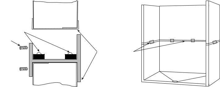
Caution: Follow steps 11-14 to anchor upper and lower sections of all two-section upright bins. Bracket must be installed to avoid possible injury should unit move.
11.Lower upper section onto lower section, taking care not to disturb gaskets and sealant beads.
12.Install icemaker according to manufacturer’s instructions.
13.From inside bin (access can be gained through lower door assembly) seal entire perimeter of seam between upper and lower sections with General Electric RTV 180 sealant provided (see figures below).
Caution: Completely cover gasket materials with sealant. Failure to properly seal sections may result in leakage and/or ice contamination and will void warranty.
14.Install supplied screws on side H-brackets and tighten, then seal entire perimeter of H-bracket with silastic.
15.Insert long side of each plastic inspection window in upper track of opening and push in to seat.
16.Remove any remaining protective plastic or temporary fastenings from doors and outside of bin.
17.Connect drain line to 1" FPT female fitting located in bottom of bin.
18.Make final connections to icemaker.
Cross section – side view
bin exterior
upper section
bead of sealant
screw
H-bracket 
Bin cutaway
bin interior
Entire inside upper and lower section seam and entire perimeter of H-bracket must be sealed with silastic provided
lower section
Installing icemaker drain
Required for some icemakers only. For these machines Follett predrills hole and provides 3/4" straight threaded drain fitting to be installed through hole. To install fitting:
1.Remove plastic nut on fitting.
2.From inside (liner side) bin, insert threaded portion through hole provided in side of bin.
3.Replace plastic nut on threaded portion and tighten against outside of bin.
4.Connect supplied tubing to icemaker drain connection after installing icemaker.
4
 Loading...