


Single Door Upright Ice Storage Bins with SmartGATE® Ice Shield
Order parts online www.follettice.com
Installation Instructions and Parts List
Welcome to Follett
Follett ice storage bins enjoy a well-deserved reputation for excellent performance, long-term reliability and outstanding after-the-sale support. To ensure that this bin delivers that same degree of service, we ask that you take a moment to review this instruction before beginning the installation of the bin. Should you have any questions or require technical
help at any point, please call our technical service group at 800 523 9361 (US & Canada) or +1 610 252 7301 and in Poland: +48 58 785 6140.
Before you begin
After uncrating and removing all packing material, inspect the equipment for concealed shipping damage. If damage is found, notify the shipper immediately and contact Follett Corporation so that we can help in the filing of a claim, if necessary.
!Important cautions
Top is NOT fastened to bin.
Avoid excessive tightening force when connecting to the bin drain fitting.
Do not apply excessive heat if any sweating of fittings is necessary. Heat conduction through metal may melt threads in plastic drain fitting.
Installation
1.Remove all packing material from bin.
2.Remove all tape and temporary fastenings from door assemblies and outside of bin.
3.Remove top from bin.
4.Remove set of four legs and any other accessories packed inside bin.
5.Lay bin on back, being careful to protect finish, and remove bolts holding skid to bin.
6.Screw legs into tapped holes in bin bottom and tighten to seat legs well against bottom.
7.Set bin upright.
8.Reinstall top onto bin.
9.Remove protective paper from stainless steel exterior.
10.Move bin to permanent location.
11.Adjust “foot” at bottom of each leg to level bin in both directions.
12.Mount icemaker(s) on bin in accordance with icemaker manufacturer's instructions.
13.Connect drain line to 1" FPT female fitting located in bottom of bin.
14.Make final connections to icemaker.
Installing icemaker drain
(Required for some icemaker applications only)
Some icemakers require a special drain system. For these machines Follett predrills the hole and provides the 3/4" straight threaded drain fitting to be installed through the hole. To install the fitting:
1.Remove plastic nut on fitting.
2.From inside bin (liner side), insert threaded portion through hole provided in side of bin.
3.Replace plastic nut on threaded portion and tighten against outside of bin.
4.Connect supplied tubing to icemaker drain connection after installing icemaker.
801 Church Lane • Easton, PA 18040, USA Toll free 800 523 9361 • +1 610 252 7301 Fax +1 610 250 0696 • www.follettice.com
EP 2138774
207890R03
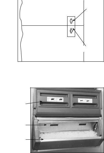
Installing icemaker tie-downs (Fig. 1) |
Fig. 1 |
|
(Required for some icemaker applications only) |
icemaker back |
15/64" |
|
||
Certain icemaker/bin combinations require installation of a tie-down |
|
hole drilled |
strap. If this fitting has been included with your bin, proceed as follows: |
|
through |
|
icemaker |
|
1. Locate icemaker back flush with bin back. |
|
|
|
wall |
|
2. Using center of vertical slot as a template, drill through |
|
|
icemaker wall with 15/64 drill. |
|
|
3.Fasten straps to icemaker and bin (bin holes are predrilled) with #14 x 1/2 sheet metal screws and washers provided.
|
bin back |
tie-down |
|
strap |
|
Removing lower door assembly |
|
|
|
|
|
(Only if required for access through narrow doors) |
|
|
1.With door in closed position, remove Phillips head screw and washer from hinge area on each side of lower access door.
2.Insert screwdriver between door and hinge bracket on one side of door and gently push against bracket to provide room for door stud to clear bracket.
3.Remove access door.
4.Pull up on SmartGATE to remove.
5.Remove screws along top of door assembly.
6.Pull forward on top of assembly and lift to remove.
access door
Reinstalling door assembly
1.Reinstall lower door assembly in bin opening.
2.Reinstall screws in hood at top of door assembly.
SmartGate
lower door assembly
3.Reinstall SmartGATE in side panel tracks and push down to seat.
4.With door in closed position, insert one door stud through hinge bracket, install washer, screw and tighten.
Note: For proper operation the access door must be reinstalled in the closed position.
5.On other side, insert screwdriver between door and hinge bracket and gently push against bracket to provide room for door stud to clear bracket.
6.Reinstall washer and screw in lift door and tighten.
7.Check door to ensure proper operation.
Operation
SmartGATE operation
Follett’s unique SmartGate positively controls the flow of ice into lower door assembly area for removal with either a scoop or shovel. SmartGate can also be adjusted and locked at one of several levels to accommodate flow characteristics of different types of ice.
Bin is shipped with SmartGate in full down position. SmartGate can be raised and locked in higher position for better flow or when more access is needed.
If more ice is needed in lower door area:
1.Use full-length handle at top of SmartGate to gently lift and jiggle SmartGate to encourage ice to flow into access area of the bin (Fig. 2). (Loose ice will cascade into lower door area.)
2.When adequate ice has flowed, push SmartGate back down.
2
 Loading...