


 REF Series
Undercounter Refrigerator
Order parts online www.follettice.com
Installation, Operation and Service Manual
Following installation, please forward this manual to the appropriate operations person.
|
801 Church Lane • PO Box D, Easton, PA 18044, USA |
|
|
|
|
Cool Ideas For Ice Management |
Toll free (800) 523-9361 • (888) 2-FOLLETT |
U® L |
|
U® L |
|
(610) 252-7301 • Fax (610) 250-0696 • www.follettice.com |
C |
00104109R06 |
|||
|
|
|

Cool Ideas For Ice Management
Follett Corporation
Equipment Return Policy
Follett equipment may be returned for credit under the following conditions:
1.The equipment is new and unused.
2.A return authorization number has been issued by customer service.
3.Follett receives the equipment at the factory in Easton, PA within 30 days of the issue of the return authorization number.
4.The equipment must be returned in Follett packaging. If the packaging has been damaged or discarded, Follett will forward, at the customer’s expense, new packaging.
Note: Return freight charges are the responsibility of the customer. If equipment is returned and is damaged because of improper packaging, Follett Corporation will not be held responsible.
Credit will be issued when:
The equipment has been inspected by Follett and deemed suitable to be returned to stock.
Note: A 15% restocking charge will be deducted from the credit. If the cost to return the product to stock exceeds 15%, the actual cost will be deducted.
2
Table of contents
Welcome to Follett. . . . . . . . . . . . . . . . . . . . . . . . . . . . . . . . . . . . . . . . . . 4 Before you begin . . . . . . . . . . . . . . . . . . . . . . . . . . . . . . . . . . . . . . . . 4
Specifications . . . . . . . . . . . . . . . . . . . . . . . . . . . . . . . . . . . . . . . . . . . . . 4
Installation procedures . . . . . . . . . . . . . . . . . . . . . . . . . . . . . . . . . . . . . . 5
Stabilizer adjustment . . . . . . . . . . . . . . . . . . . . . . . . . . . . . . . . . . . . . 5 Sealing the unit. . . . . . . . . . . . . . . . . . . . . . . . . . . . . . . . . . . . . . . . . . 5 Shelving adjustment . . . . . . . . . . . . . . . . . . . . . . . . . . . . . . . . . . . . . .5
Reversing door. . . . . . . . . . . . . . . . . . . . . . . . . . . . . . . . . . . . . . . . . . 5 Changing the temperature set point . . . . . . . . . . . . . . . . . . . . . . . . . 6
Operation . . . . . . . . . . . . . . . . . . . . . . . . . . . . . . . . . . . . . . . . . . . . . . . . . 7
How the refrigerator works . . . . . . . . . . . . . . . . . . . . . . . . . . . . . . . . 7
Temperature control . . . . . . . . . . . . . . . . . . . . . . . . . . . . . . . . . . . . . 7
Defrosting . . . . . . . . . . . . . . . . . . . . . . . . . . . . . . . . . . . . . . . . . . . . . 7
Cleaning. . . . . . . . . . . . . . . . . . . . . . . . . . . . . . . . . . . . . . . . . . . . . . . 7
Service information . . . . . . . . . . . . . . . . . . . . . . . . . . . . . . . . . . . . . . . . . 8
Latch adjustment . . . . . . . . . . . . . . . . . . . . . . . . . . . . . . . . . . . . . . . . 8 Gasket replacement . . . . . . . . . . . . . . . . . . . . . . . . . . . . . . . . . . . . . 8
Slide-out compressor tray . . . . . . . . . . . . . . . . . . . . . . . . . . . . . . . . . 8 Wiring diagram . . . . . . . . . . . . . . . . . . . . . . . . . . . . . . . . . . . . . . . . . 8
Refrigeration system diagram . . . . . . . . . . . . . . . . . . . . . . . . . . . . . . 9 Troubleshooting guide . . . . . . . . . . . . . . . . . . . . . . . . . . . . . . . . . . . 10
Accessory information . . . . . . . . . . . . . . . . . . . . . . . . . . . . . . . . . . . . .11
Temperature alarm. . . . . . . . . . . . . . . . . . . . . . . . . . . . . . . . . . . . . . 11
Pyxis . . . . . . . . . . . . . . . . . . . . . . . . . . . . . . . . . . . . . . . . . . . . . . . . 12
Replacement parts . . . . . . . . . . . . . . . . . . . . . . . . . . . . . . . . . . . . . . . . 13
3

Welcome to Follett
Follett equipment enjoys a well-deserved reputation for excellent performance, long-term reliability and outstanding after-the-sale support. To ensure that this product delivers that same degree of service, we ask that you take a moment to review this manual before beginning the installation. Should you have any questions or require technical help at any point, please call our technical service group at (800) 523-9361, (888) 2-FOLLETT or (610) 252-7301.
Before you begin
After uncrating and removing all packing material, inspect the equipment for concealed shipping damage. If damage is found, notify the shipper immediately and contact Follett Corporation so that we can help in the filing of a claim, if necessary.
Specifications
Series specifications
REF4-ADA |
31.5" height |
fits below 34" high ADA-compatible counter |
4.0 cu ft capacity |
REF5 |
34.5" height |
fits below standard 36" high counter |
4.8 cu ft capacity |
Electrical specifications
115V, 60Hz, 1 phase Full load amps: 8.0
Minimum circuit ampacity: 15 amp
Maximum size of branch circuit overcurrent device: 15 amp
Refrigeration specifications
Refrigerant – R404A
Charge size – 8 oz
Maximum design pressures:
High side – 375psi
Low side – 174psi
Installation specifications
Ambient temperature must not exceed 100°F (38°C).
The front louvered panel must be kept free of any cabinet trim or obstructions to assure proper ventilation of the refrigeration system.
 Important cautions
Equipment must be wired according to local and NEC codes.
Always disconnect power before servicing refrigerator.
4
Installation
Fig. 1
Stabilizer adjustment
Leveling the unit is important to the proper operation of the refrigeration system. After the refrigerator is positioned in the desired mounting location, remove the lower front panel to access the stabilizer legs on the base of the unit. The refrigerator is shipped with the stabilizer legs in the fully retracted position. They may be adjusted independently by turning clockwise to lower, or counterclockwise to raise the stabilizer leg.
Sealing the unit
Once unit is in the final location, apply a thick bead (minimum 1/4" (6mm) diameter) of NSF-listed silicone sealant (Dow Corning RTV-732 or equivalent) to the base of the unit, sealing it to the floor.
Shelving adjustment
The epoxy-coated wire shelves may be adjusted in .5" increments.
1.Remove shelf.
2.Remove each shelf bracket by applying pressure and lifting bottom tab up and out of pilaster.
3.Insert each shelf bracket in new location by inserting top curved tab and applying pressure while inserting lower tab.
4.Reinsert shelf.
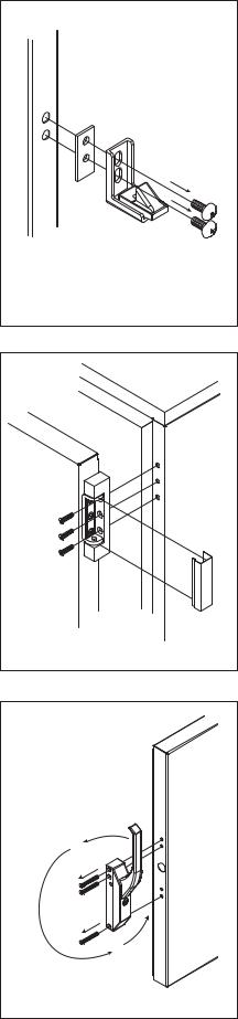
Reversing door
1.Remove screws from latch assembly (Fig. 1).
2.Carefully remove hinge covers with a flat screwdriver (Fig. 2A). Note: Use caution to avoid scratching covers with screwdriver.
3.Remove screws from hinges while supporting door (Fig. 2B).
4.Remove plugs from identical hinge holes on reverse side of cabinet.
5.Reverse door and mount hinges by reinserting screws.
6.Fill holes from original hinge location with plugs removed from other side.
7.Mount latch by reinserting screws.
8.Remove screws from handle assembly (Fig. 3A).
9.Rotate handle to the upright position (Fig. 3B).
10.Mount handle by reinserting screws.
A
B
Fig. 2
B |
A |
Fig. 3
A
A
B
5
 Loading...