


 Loading...
99 Washington Street
Melrose, MA 02176
Fax 781-665-0780 ¨
TestEquipmentDepot.com
Ti40, Ti45, Ti50, Ti55
IR FlexCam Thermal Imager
Users Manual
May 2006
2006 Fluke Corporation, All rights reserved.
All product names are trademarks of their respective companies.
Test Equipment Depot - 800.517.8431 - 99 Washington Street Melrose, MA 02176
FAX 781.665.0780 - TestEquipmentDepot.com
Table of Contents
Chapter |
Title |
Page |
|
1 |
Introduction .............................................................................. |
|
1-1 |
|
Introduction .......................................................................................... |
|
1-1 |
|
Contacting Fluke................................................................................... |
|
1-2 |
|
Safety Information ................................................................................ |
|
1-2 |
|
Standard Accessories ............................................................................ |
|
1-4 |
|
Charge and Insert Battery ..................................................................... |
|
1-6 |
|
Power Camera On................................................................................. |
|
1-7 |
|
Insert Memory Card.............................................................................. |
|
1-8 |
|
Focus..................................................................................................... |
|
1-9 |
|
Set Temperature Level and Span .......................................................... |
1-10 |
|
|
Set IR Fusion Blend Level - Ti45, Ti50, Ti55 with Fusion................... |
1-10 |
|
|
Capturing an Image............................................................................... |
|
1-11 |
|
SmartView Software for Your PC ........................................................ |
1-13 |
|
2 |
Camera Overview ..................................................................... |
|
2-1 |
|
Introduction .......................................................................................... |
|
2-1 |
|
Camera Parts......................................................................................... |
|
2-2 |
|
Camera Display Screen......................................................................... |
|
2-6 |
|
Programming Function Buttons............................................................ |
|
2-10 |
|
Using Display Screen Menus................................................................ |
|
2-12 |
|
Inserting and Removing Memory Card................................................. |
2-13 |
|
3 |
Basic Operation........................................................................ |
|
3-1 |
|
Acquiring and Reviewing Images......................................................... |
3-1 |
|
|
Scan Target ....................................................................................... |
|
3-1 |
|
Pause/Save Image ............................................................................. |
|
3-1 |
|
View Saved Image ............................................................................ |
|
3-2 |
|
Delete Saved Image .......................................................................... |
|
3-2 |
|
Electronic Zoom ................................................................................... |
|
3-3 |
|
Saved Image Information...................................................................... |
|
3-4 |
4 |
Analyzing and Enhancing Images .......................................... |
4-1 |
|
|
Setting Emissivity and Background Temperature................................. |
4-1 |
|
|
Fixed Image Function ....................................................................... |
|
4-2 |
|
Changing Color Palettes ....................................................................... |
|
4-3 |
|
Setting Temperature Level and Span .................................................... |
4-3 |
|
i

Ti40, Ti45, Ti50, Ti55
Users Manual
|
Manual Level and Span.................................................................... |
4-3 |
|
Automatic Level and Span ............................................................... |
4-4 |
|
Arbitrary Fixed Temperature Level and Span .................................. |
4-5 |
|
Using Palette Saturation Colors............................................................ |
4-6 |
|
Creating an Isotherm Temperature Band.............................................. |
4-8 |
|
Using Display Screen Temperature Markers........................................ |
4-9 |
|
Annotations .......................................................................................... |
4-11 |
|
Adding Annotations to Saved Images .............................................. |
4-11 |
|
Creating Annotations Lists in SmartView........................................ |
4-14 |
5 |
Visible Light Camera Module (VLCM) .................................... |
5-1 |
|
Enabling/Disabling Visible Light Camera Module .............................. |
5-1 |
|
Using Image Alignment ....................................................................... |
5-2 |
|
Focusing ............................................................................................... |
5-2 |
|
Adjusting IR-VL Fusion Blend Level .................................................. |
5-2 |
|
Using Full Screen or Picture-in-Picture View ...................................... |
5-3 |
|
Adjusting Brightness and Color Controls............................................. |
5-4 |
|
Using Torch Control............................................................................. |
5-5 |
|
Using Visible Light Flash..................................................................... |
5-5 |
|
Recording Visible Light Images........................................................... |
5-6 |
|
Using Laser Pointer.............................................................................. |
5-7 |
|
Using Thumbnail Browser ................................................................... |
5-7 |
|
Using Color Alarms ............................................................................. |
5-7 |
|
Using Menu to Adjust Color Alarm Ranges..................................... |
5-8 |
|
Using Palette Bar to Adjust Color Alarm Ranges ............................ |
5-10 |
6 |
Camera Setup........................................................................... |
6-1 |
|
Adjusting Display Screen Brightness ................................................... |
6-1 |
|
Hiding Display Screen Task Bar .......................................................... |
6-2 |
|
Hiding Display Screen Color Palette.................................................... |
6-2 |
|
Setting Temperature Units.................................................................... |
6-3 |
|
Setting Temperature Calibration Range ............................................... |
6-3 |
|
Changing Lens Selection...................................................................... |
6-4 |
|
Setting Date and Time.......................................................................... |
6-4 |
|
Saving and Reloading Camera Settings................................................ |
6-6 |
|
Naming Image Files ............................................................................. |
6-7 |
|
Changing Image File Name Prefix ....................................................... |
6-7 |
|
Resetting Image File Name Sequence Number .................................... |
6-8 |
|
Selecting Video Output Options........................................................... |
6-9 |
7 |
Advanced Operation................................................................ |
7-1 |
|
Enhancing the Image............................................................................ |
7-1 |
|
Using Auto Capture.............................................................................. |
7-2 |
|
Using User-Defined Display Screen Temperature Markers ................. |
7-4 |
|
Using Internal Recalibration................................................................. |
7-7 |
8 |
Camera Care............................................................................. |
8-1 |
|
Cleaning the IR Lens, VLCM, Display Screen, and Body ................... |
8-1 |
|
Using Other Lenses .............................................................................. |
8-2 |
|
Viewing Camera and Battery Information............................................ |
8-2 |
ii
|
|
Contents (continued) |
|
|
|
Charging the Batteries .......................................................................... |
8-3 |
|
Recalibrating the Batteries.................................................................... |
8-4 |
|
Conserving Battery Power .................................................................... |
8-5 |
|
Appendices |
|
|
A |
Glossary ........................................................................................ |
A-1 |
B |
Troubleshooting............................................................................ |
B-1 |
C |
Emissivity Values ......................................................................... |
C-1 |
D |
Camera Specifications and Dimensions........................................ |
D-1 |
E |
Resources and References............................................................. |
E-1 |
F |
Camera Default Settings ............................................................... |
F-1 |
Index
iii

Ti40, Ti45, Ti50, Ti55
Users Manual
iv
List of Tables
Table |
Title |
Page |
1-1. |
Standard Accessories ..................................................... |
1-6 |
2-1. |
Camera Parts--Descriptions............................................ |
2-4 |
2-2. |
Display Screen--Descriptions......................................... |
2-8 |
2-3. |
Programmable Functions................................................ |
2-10 |
4-1. |
Standard Saturation Colors............................................. |
4-7 |
8-1. |
Remaining Battery Charge Indicators ............................ |
8-3 |
8-2. |
Battery Charging Status ................................................. |
8-4 |
B-1. |
Troubleshooting Tips ..................................................... |
B-1 |
C-1. |
Emissivity Values of Common Materials ...................... |
C-1 |
D-1. |
Camera Specifications, Ti45 and Ti40........................... |
D-1 |
D-2. |
Camera Specifications, Ti50 and Ti55 Models.............. |
D-7 |
F-1. |
Default Settings, Ti45 and Ti40 Models ........................ |
F-1 |
F-2. |
Default Settings, Ti55 and Ti50 Models ........................ |
F-7 |
v

Ti40, Ti45, Ti50, Ti55
Users Manual
vi
List of Figures
Figure |
Title |
Page |
1-1. |
Standard Accessories ..................................................... |
1-5 |
1-2. |
Inserting the Battery....................................................... |
1-7 |
1-3. |
Turning the Power On and Off....................................... |
1-8 |
1-4. |
Inserting a Memory Card ............................................... |
1-9 |
1-5. |
Focusing the Camera...................................................... |
1-9 |
1-6. |
Setting the Level and Span............................................. |
1-10 |
1-7. |
Setting the Fusion Blend Level ...................................... |
1-11 |
1-8. |
Capturing an Image ........................................................ |
1-12 |
2-1. |
Camera Back View ........................................................ |
2-3 |
2-2. |
Camera Front and Top View.......................................... |
2-3 |
2-3. |
Camera Bottom View..................................................... |
2-3 |
2-3. |
Camera Bottom View..................................................... |
2-3 |
2-4. |
Camera Display Screen--Example 1 .............................. |
2-6 |
2-5. |
Camera Display Screen--Example 2 .............................. |
2-7 |
2-6. |
Camera Display Screen--Example 3 .............................. |
2-7 |
2-7. |
Inserting and Removing a Memory Card....................... |
2-13 |
B-1. |
Serial/Part Number and Laser Certifiction Location...... |
B-4 |
D-1. |
Camera Dimensions ....................................................... |
D-13 |
D-2. |
Camera Dimensions - Height and Width ....................... |
D-13 |
vii

Ti40, Ti45, Ti50, Ti55
Users Manual
viii
Chapter 1
Introduction
Introduction
Thank you for choosing the IR FlexCam® portable infrared camera (hereafter, “Camera”). This award-winning Camera offers some of the most advanced yet most intuitive, fully-radiometric solutions available. The visible light camera module (VLCM) and IR Fusion functions (on select models only) make it easier than ever to manage and analyze images captured with this system and improve reporting abilities. The unique control image and IR Fusion technology enables you to combine visible light images—like a normal digital camera—and infrared images together to create a single image with greatly enhanced detail. This is especially helpful in low contrast scenes where the temperature differential is minimal and the infrared image appears to be all one color.
The IR FlexCam is available in 4 models. The Ti40 and Ti45 cameras uses a detector with 160 x 120 resolution. The Ti50 and Ti55 cameras use a detector with 320 x 240 resolution. Refer to Appendix D for specific features available on your camera.
Your Camera is powerful and easy to use in a wide range of applications including:
Predictive Maintenance
•Electrical Systems—Identify circuit overloads before they happen.
•Mechanical Systems—Reduce downtime and prevent failures.
•Utilities—Monitor substations, transmission lines, etc. efficiently and accurately.
Building Science
•Roofing—Detect and isolate water saturation quickly and efficiently.
•Building Envelope—Perform commercial and residential infrared energy audits.
1-1

Ti40, Ti45, Ti50, Ti55
Users Manual
•Moisture Detection—Get to the source of moisture and mold growth.
•Restoration—Evaluate remediation work to make sure area is completely dry.
Research and Development
•Visualize and quantify generated heat patterns to improve products and the processes used to create them.
Process Monitoring
•Monitor and observe temperatures of processes in real-time.
To quickly take advantage of the many functions your Camera offers, we recommend that you carefully read this manual. It is designed to familiarize you with the most important aspects of your camera and guide
you in using the features of this system. This manual provides instruction on how to capture high quality images; however, thermography is a sophisticated field often requiring special training that is not covered in this manual. If you would like information on thermography training, contact Fluke Corporation .
Safety Information
Use your Camera only as specified in this manual.
A WWarning identifies hazardous conditions and actions that could cause bodily harm or death.
1-2

Introduction 1
Safety Information
A WCaution identifies conditions and actions that could damage the camera or cause permanent loss of data.
WCaution
•To avoid damaging your Camera, treat it with care as you would any type of precision equipment.
•Your infrared camera is a precision instrument that uses a sensitive infrared (IR) detector. Pointing your camera towards highly-intense energy sources—including devices that emit laser radiation and reflections from these devices—may adversely affect camera accuracy and may harm or permanently damage your camera’s IR detector.
•Your camera was calibrated prior to shipping. We recommend that you have your camera checked for proper calibration every two years. Some ISO 9000 programs require more frequent checks for certification. Contact Fluke for details.
•Your camera requires three minutes to warm up before accurate measurements are available.
*WWarning
•Your camera contains a Class 2 laser pointer. See diagram in Appendix B for laser aperture location.
•To avoid eye damage, do not point laser directly at eye or indirectly off reflective surfaces.
•Use of controls or adjustments or performance or procedures other than those specified herein may result in hazardous laser radiation exposure.
•Do not use camera in a manner not specified in this manual or the protection provided by the equipment may be impaired.
1-3

Ti40, Ti45, Ti50, Ti55
Users Manual
/ Note This camera contains a lithium battery.
Do not mix with the solid waste stream. Spent batteries should be disposed of by a qualified recycler or hazardous materials handler.
Contact your authorized Fluke Service Center for recycling information.
Standard Accessories
If any of the standard accessories shown in Figure 1-1 and described in Table 1-1 are missing or damaged, contact a Fluke customer service representative.
1-4

|
Introduction |
1 |
|
Standard Accessories |
|
3 |
|
|
4 |
5 |
|
|
|
|
6 |
7 |
|
|
|
|
|
10 |
|
8 |
9 |
|
|
15 |
|
11 |
14 |
|
|
|
|
12 |
13 |
|
|
16 |
|
|
|
eii001.eps |
Figure 1-1. Standard Accessories
1-5

Ti40, Ti45, Ti50, Ti55
Users Manual
|
Table 1-1. Standard Accessories |
|
|
Number |
Description |
|
|
A |
Portable Infrared Camera with Lens Cap |
|
|
B |
Camera Carrying Case |
|
|
C |
LCD Cleaning Cloth |
|
|
D |
AC adapters (2) |
|
|
E |
Auxiliary AC Power Supply (Ti45 and Ti55 only) |
|
|
F |
AC Patch Cord |
|
|
G |
Neck Strap |
|
|
H |
Video Cable |
|
|
I |
AC Power Supply |
|
|
J |
Battery Charger |
|
|
K |
Compact Flash Memory Card with PCMCIA Adapter |
|
|
L |
Two Rechargeable Batteries |
|
|
M |
Compact Flash Memory Card Reader with USB Adapter |
|
|
N |
Getting Started Guide |
|
|
O |
SmartView Software CD with complete users manuals |
|
|
P |
Compact Flash Software CD |
|
|
Charge and Insert Battery
Charge the batteries for 3 hours before use. Use only the rechargeable batteries supplied. A battery is fully charged when the green LED light on the charger remains solid.
Insert the charged battery into the slot on the bottom of the camera as shown in Figure 1-2.
Note
You may use the auxiliary AC power supply to connect the camera to a working AC outlet until at least one of the batteries is charged.
1-6

Introduction 1
Power Camera On
eii002.eps
Figure 1-2. Inserting the Battery
Power Camera On
With a charged battery inserted, or AC power supply connected, press Das shown in Figure 1-3. Dlights up green, and the start-up screen appears after approximately 10 seconds.
Note
After powering on your camera, the camera requires a boot up and warm up period of approximately 30 seconds in order to maintain a crisp, clear, real-time image. Three minutes after powering on the camera, the temperature measurement accuracy will be within the specification requirements.
1-7

Ti40, Ti45, Ti50, Ti55
Users Manual
On/Off
F2
F3
eii003.eps
Figure 1-3. Turning the Power On and Off
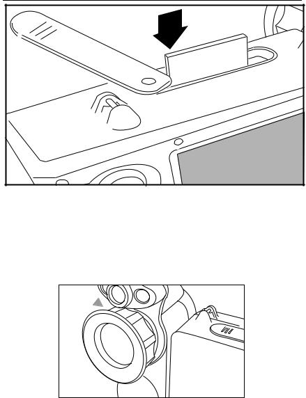
Insert Memory Card
1.Pull cover up and rotate as shown in Figure 1-4.
2.Insert the Compact Flash memory card into the slot with the card’s connection end pointed at the camera and the label with MB size facing the back of the camera.
3.Look for the “Compact Flash Card inserted” message on the camera display screen.
4.Close the cover.
1-8
Introduction |
1 |
Focus |
|
|
eii004.eps |
Figure 1-4. Inserting a Memory Card
Focus
Remove the lens cap, point the lens at the target, and manually rotate the lens with your finger, as shown in Figure 1-5, until the image is in focus.
eii005.eps
Figure 1-5. Focusing the Camera
1-9

Ti40, Ti45, Ti50, Ti55
Users Manual
Set Temperature Level and Span
1.Press Gas shown in Figure 1-6 to automatically set the camera’s temperature level and span.
2.Press Gagain as needed to properly scale the image.
Level & Span
eii006.eps
Figure 1-6. Setting the Level and Span
Set IR Fusion Blend Level - Ti45, Ti50, Ti55 with Fusion
1.Press and hold Guntil the IR Fusion blend level control box appears on the display screen.
2.While continuing to press G, use the MOUSE controller shown in Figure 1-7 to slide the IR Fusion blend level bar in the control box to the desired setting.
3.Tap the TRIGGER button to retain settings.
Test Equipment Depot - 800.517.8431 - 99 Washington Street Melrose, MA 02176
1-10 |
FAX 781.665.0780 - TestEquipmentDepot.com |
Introduction 1
Capturing an Image
Mouse Controller
F2
F2
F3
Level & Span
eii007.eps
Figure 1-7. Setting the Fusion Blend Level
Capturing an Image
1.Tap the TRIGGER button once (shown in Figure 1-8) to pause the live image.
2.Review the image and camera settings.
3.Press and hold the TRIGGER button for 2 seconds to capture (save) the image. The image file name appears in the upper left-hand corner of the display screen indicating the image is saved on the memory card.
Note
The memory card must be inserted into the camera to save and store images.
4.Tap the TRIGGER button to return to scan target mode.
1-11

Ti40, Ti45, Ti50, Ti55
Users Manual
Trigger
eii008.eps
Figure 1-8. Capturing an Image
1-12

Introduction 1
SmartView Software for Your PC
SmartView Software for Your PC
Your system includes a CD containing SmartView™ software that you install on your personal computer. SmartView, together with your Camera, enables you to:
•Transfer thermographic images to a computer and efficiently manage them
•Optimize and analyze your infrared and visible light control images
•Create and print detailed, professional reports containing important image data
SmartView image analysis software is compatible with any personal computer running Microsoft Windows 98/ME/2000/XP. This software is provided on the SmartView CD-ROM disk included with your camera.
To install SmartView software on your computer:
1.Start your computer and close any open applications.
2.Insert the CD-ROM disk containing the SmartView software in the CD-ROM drive.
After a moment, the installation program should start automatically. If the installation program does not start automatically, use Windows explorer to locate the file named “setup.exe” on the CD-ROM disk. Start the installation by double clicking the “setup.exe” file.
3.Follow the on-screen instructions to complete the installation.
1-13

Ti40, Ti45, Ti50, Ti55
Users Manual
1-14
Chapter 2
Camera Overview
Introduction
Your Camera is a compact, lightweight system that offers a generous five-inch display module you can position for optimal viewing. You can also rotate the lens module to easily capture target images on ceilings, hidden above high objects, under low obstacles, or in other hard-to-reach places. In addition, you can position the camera for comfortable desktop image analysis and can mount the system on a standard tripod to continuously monitor a single location. Although your Camera is a sophisticated imaging system with many advanced functions, it is easy to operate using buttons, mouse-controlled menu options, or a combination of both.
The visible light camera module (VLCM), available on select Camera systems, adds a 1.3 mega pixel visible light sensor that improves your ability to identify and analyze thermal anomalies and to provide visible light control images for your reports.
2-1
Ti40, Ti45, Ti50, Ti55
Users Manual
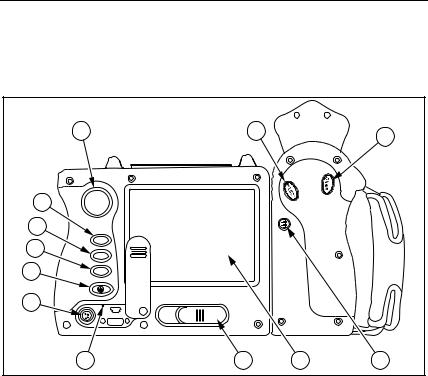
Camera Parts
Camera features and controls are shown in Figures 2-1, 2-2, and 2-3 and described in Table 2-1.
1 |
|
2 |
3 |
|
|
|
|
4 |
|
|
|
5 |
|
|
|
6 |
F1 |
|
|
F2 |
|
|
|
|
|
|
|
7 |
F3 |
|
|
|
|
|
|
8 |
|
|
|
9 |
10 |
11 |
12 |
|
|
|
eii009.eps |
Figure 2-1. Camera Back View
2-2

|
|
Camera Overview |
2 |
|
|
Camera Parts |
|
|
14 |
|
|
15 |
16 |
|
|
|
|
21 |
|
1 |
|
19 |
|
|
|
|
|
20 |
|
|
|
|
17 |
18 |
|
|
|
|
eii010.eps |
Figure 2-2. Camera Front and Top View
22 |
23 |
|
eii011.eps |
Figure 2-3. Camera Bottom View
2-3

Ti40, Ti45, Ti50, Ti55
Users Manual
Table 2-1. Camera Parts--Descriptions
AMouse controllerÑUsed to control the pointer position in images and text menus.
BEbuttonÑPerforms mouse click, or ÒenterÓ function, for the pointer.
CFbuttonÑUsed to access display screen menus. Note: Tap Fonce and a popup menu appears.
AProgrammable function buttonÑCan be programmed to perform
Ddifferent menu functions, see Programming Function Buttons later in this Chapter.
BProgrammable function buttonÑCan be programmed to perform
Edifferent menu functions, see Programming Function Buttons later in this Chapter.
CProgrammable function buttonÑCan be programmed to perform
Fdifferent menu functions, see Programming Function Buttons later in this Chapter.
DbuttonÑUsed to power camera on and off and to place the camera
Gin a low-power standby mode to conserve battery power.
Solid green = power is on; Blinking green = standby mode enabled.
HAuxiliary power portÑConnection port for AC to DC power adapter.
IResetÑHidden switch to reset camera. Can be accessed with a paper clip. See, Appendix BÑTroubleshooting.
J |
Battery latchÑUsed to remove battery. |
|
|
K |
Liquid Crystal Display (LCD) screenÑSunlight-readable color display |
for viewing images and accessing camera menu functions. |
|
|
|
|
GLEVEL & SPAN buttonÑUsed to rescale the color palette to the |
L maximum and minimum temperatures in current image and to adjust IR |
|
|
Fusion level. |
|
|
M |
Infrared lensÑInfrared Germanium lens with manual focus. |
|
|
|
Torch/FlashÑWhen enabled, the torch illuminates darker work areas. |
NWhen enabled, the flash lights the target object during image capture for better-quality visible light images. The torch and flash can be enabled at
the same time.
2-4

Camera Overview 2
Camera Parts
Table 2-1. Camera Parts--Descriptions (cont.)
OVisible light lensÑCaptures visible light control images.
PLaserÑUsed to point out the object you are aiming the camera towards.
Trigger buttonÑUsed to pause and/or save an image frame. Also used
Qto accept a setting change (i.e., OK click), close a menu page, and to return to scan target mode.
RVideo portÑRCA video jack used to connect camera to a TV or video monitor.
SCompactFlash memory card slotÑEjection button and slot for CompactFlash memory card.
THand strapÑAdjustable strap for added stability when capturing images.
UNeck strap mountÑPins for attaching neck and/or shoulder strap.
VTripodtripod. mountÑStandard 1/4-20 threaded hole for mounting camera on
WBatteryÑFluke 7-volt lithium-ion battery for primary power.
2-5
Ti40, Ti45, Ti50, Ti55
Users Manual
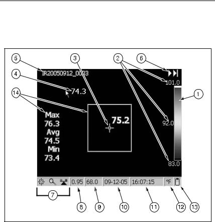
Camera Display Screen
Display screen features and controls are shown in Figures 2-4, 2-5, and 2-6 and described in Table 2-2.
eii012.eps |
Figure 2-4. Camera Display Screen--Example 1
2-6
Loading...