


 Loading...
T.O. 33A6-4-30-1
RPM3/HPMS A30000/A6000-AF
Operation and Maintenance
Manual
NSN 6685-01-470-8667 (2 of 2)
1 August 2000
©2000 DH Instruments, Inc.

RPM3/HPMS A30000/A6000-AF Operation and Maintenance Manual

 High pressure liquids and gases are potentially hazardous. Energy stored in these liquids and gases can be released unexpectedly and with extreme force. High pressure systems should be assembled and operated only by personnel who have been instructed in proper safety practices.
© 2000 DH Instruments, Inc. All rights reserved.
Information in this document is subject to change without notice. No part of this document may be reproduced or transmitted in any form or by any means, electronic or mechanical, for any purpose, without the express written permission of DH Instruments, Inc. 4765 East Beautiful Lane Phoenix AZ 85044-5318 USA.
DH Instruments makes sincere efforts to ensure accuracy and quality of its published materials; however, no warranty, expressed or implied, is provided. DH Instruments disclaims any responsibility or liability for any direct or indirect damages resulting from the use of the information in this manual or products described in it. Mention of any product does not constitute an endorsement by DH Instruments of that product. This manual was originally composed in English and was subsequently translated into other languages. The fidelity of the translation cannot be guaranteed. In case of conflict between the English version and other language versions, the English version predominates.
DH Instruments, DH, DHI, AutoZ, CalTool, HGC, HPMS, OPG1, PPC, PPC2+, RPM3, SDS (Self Defense System) are trademarks, registered and otherwise.
LabVIEW is a registered trademark of National Instruments Corporation.
Document No. 550115 000124
Printed in the USA.
©2000 DH Instruments, Inc.

RPM3/HPMS A30000/A6000-AF Operation and Maintenance Manual
TABLE OF CONTENTS
TABLE OF CONTENTS ................................................................................ |
i |
||||
TABLES |
.................................................................................................... |
|
|
|
v |
FIGURES ................................................................................................. |
|
|
|
vi |
|
ABOUT THIS MANUAL ............................................................................. |
vii |
||||
1 . INTRODUCTION |
.................................................................................... |
|
1 |
||
1.1 |
PRODUCT OVERVIEW ....................................................................................................................... |
1 |
|||
1.2 |
SPECIFICATIONS ............................................................................................................................... |
2 |
|||
|
1.2.1 |
GENERAL ...............................................................................................................................SPECIFICATIONS |
2 |
||
|
1.2.2 |
PRESSURE ...............................................................................................MEASUREMENT SPECIFICATIONS |
2 |
||
|
|
1.2.2.1 ............................................RPT MEASUREMENT SPECIFICATIONS (% FS OF ACTIVE RANGE) |
3 |
||
|
|
1.2.2.2 ................................................................................................................... |
ON - BOARD BAROMETER |
4 |
|
2. INSTALLATION ..................................................................................... |
|
|
5 |
||
2.1 |
UNPACKING AND .........................................................................................................INSPECTION |
5 |
|||
|
2.1.1 |
REMOVING .........................................................................................................................FROM PACKAGING |
5 |
||
|
2.1.2 |
INSPECTING .....................................................................................................................................CONTENTS |
5 |
||
2.2 |
SITE REQUIREMENTS........................................................................................................................ |
6 |
|||
2.3 |
INITIAL SETUP ................................................................................................................................... |
|
|
6 |
|
|
2.3.1 |
PREPARING ...........................................................................................................................FOR OPERATION |
6 |
||
|
2.3.2 RPM3/HPMS .........................................................................................................FRONT AND REAR PANELS |
7 |
|||
|
|
2.3.2.1 ...................................................................................................................................... |
FRONT PANEL |
7 |
|
|
|
2.3.2.2 ........................................................................................................................................ |
REAR PANEL |
8 |
|
|
|
2.3.2.3 ............................................................................................................................................ |
SIDE VIEW |
8 |
|
|
2.3.3 RPM3 FRONT ....................................................................................................................AND REAR PANELS |
9 |
|||
|
|
2.3.3.1 ...................................................................................................................................... |
FRONT PANEL |
9 |
|
|
|
2.3.3.2 ...................................................................................................................................... |
REAR PANEL |
10 |
|
|
2.3.4 |
POWER CONNECTION....................................................................................................................................... |
10 |
||
|
2.3.5 |
FOOT SWITCH ...........................................................................................................................CONNECTION |
11 |
||
|
2.3.6 |
TEST PORT ................................................................................................................................CONNECTION |
11 |
||
|
|
2.3.6.1 .......................................................................................................................THE RPM3 ATM PORT |
11 |
||
|
2.3.7 SETTING .......................................................................................................................UP FILE SEQUENCES |
12 |
|||
2.4 POWER UP AND .....................................................................................................VERIFICATION |
12 |
||||
|
2.4.1 |
APPLY POWER ................................................................................................................................................... |
12 |
||
|
2.4.2 CHECK PROPER .......................................................................PRESSURE MEASUREMENT OPERATION |
12 |
|||
|
|
2.4.2.1 .......................................................CHECKING ABSOLUTE MODE PRESSURE MEASUREMENT |
12 |
||
|
|
2.4.2.2 .............................................................CHECKING GAUGE MODE PRESSURE MEASUREMENT |
13 |
||
2.5 |
SHORT TERM STORAGE ................................................................................................................. |
13 |
|||
2.6 LONG TERM STORAGE .........................................................................................AND SHIPPING |
13 |
||||
3. OPERATION ....................................................................................... |
|
|
15 |
||
3.1 |
GENERAL/MANUAL ....................................................................................................OPERATION |
15 |
|||
|
3.1.1 KEYPAD ................................................................................................................LAYOUT AND PROTOCOL |
15 |
|||
|
3.1.2 |
MAIN RUN ............................................................................................................................................SCREEN |
16 |
||
|
3.1.3 |
SOUNDS............................................................................................................................................................... |
|
|
17 |
|
3.1.4 |
SOFT [ON/OFF] ...........................................................................................................................................KEY |
17 |
||
|
3.1.5 |
PRESSURE READY <*>/NOT READY (<↑↑ > OR <↓↓ >) INDICATION |
................................................................ |
18 |
|
Page i |
©2000 DH Instruments, Inc. |

RPM3/HPMS A30000/A6000-AF Operation and Maintenance Manual
|
3.1.6 |
MULTIPLE PRESSURE RANGES ...................................................................................................................... |
18 |
|
|
|
3.1.6.1 |
RANGES AND IDENTIFICATION ....................................................................................................... |
19 |
|
3.1.7 |
AUTOMATED TEST/CALIBRATION SEQUENCES .......................................................................................... |
19 |
|
|
3.1.8 |
HPMS (HIGH PRESSURE MOUNTING SYSTEM)............................................................................................. |
20 |
|
3.2 |
DIRECT FUNCTION KEYS ................................................................................................................ |
22 |
||
|
3.2.1 |
DIRECT FUNCTION KEYS SUMMARY.............................................................................................................. |
22 |
|
|
3.2.2 |
[RANGE] |
............................................................................................................................................................... |
24 |
|
3.2.3 |
[UNIT] ................................................................................................................................................................... |
|
26 |
|
3.2.4 |
[MODE]................................................................................................................................................................. |
|
27 |
|
3.2.5 |
[UL] (UPPER ............................................................................................................................................LIMIT) |
28 |
|
|
|
3.2.5.1 ...................................................................................... |
OVER - PRESSURE FUNCTION (<PMAX!>) |
30 |
|
|
3.2.5.2 ................................................................................ |
LO RPT PROTECTION (<!!LO RPT ACTIVE!!>) |
31 |
|
3.2.6 |
[RES] (RESOLUTION)......................................................................................................................................... |
31 |
|
|
3.2.7 |
[DISPLAY] ............................................................................................................................................................ |
33 |
|
|
|
3.2.7.1 ................................................................................................................................ |
AVG (AVERAGE) |
34 |
|
|
3.2.7.2 .................................................................................................................................................... |
RATE |
36 |
|
|
3.2.7.3 ............................................................................................................................... |
DEV (DEVIATION) |
36 |
|
|
3.2.7.4 ...................................................................................................................................................... |
RPT |
37 |
|
|
3.2.7.5 .................................................................................................................................................... |
HI/LO |
39 |
|
|
3.2.7.6 ............................................................................................................................................... |
FREEZE |
39 |
|
|
3.2.7.7 ................................................................................................................................................. |
CLEAN |
40 |
|
3.2.8 |
[HEAD] ................................................................................................................................................................. |
|
41 |
|
3.2.9 |
[SDS] (SELF .....................................................................................................................DEFENSE SYSTEM) |
44 |
|
|
3.2.10 |
[AUTOZ] ............................................................................................................................................................... |
|
44 |
|
|
3.2.10.1 .................................................................. |
RUNNING AUTOZ IN GAUGE MEASUREMENT MODE |
44 |
|
|
3.2.10.2 ............................................................ |
RUNNING AUTOZ IN ABSOLUTE MEASUREMENT MODE |
45 |
|
3.2.11 |
[ENTER] ......................................................................................................................RUN TEST SEQUENCE |
49 |
|
|
|
3.2.11.1 ................................................................................... |
TEST INITIALIZATION (QUICK SEQUENCE) |
51 |
|
|
3.2.11.2 .................................................. |
TEST EXECUTION (QUICK SEQUENCE AND FILE SEQUENCE) |
52 |
3.3 |
[SETUP] MENU .........................................................................................................................KEY |
54 |
||
|
3.3.1 |
HEAD .................................................................................................................................................................... |
|
54 |
|
3.3.2 |
PRESU.................................................................................................................................................................. |
|
55 |
|
3.3.3 |
READRT ......................................................................................................................................(READ RATE) |
56 |
|
|
3.3.4 |
STAB (STABILITY) .............................................................................................................................................. |
57 |
|
|
3.3.5 |
LEAK (LEAK .........................................................................................................................................CHECK) |
59 |
|
|
3.3.6 |
SEQ....................................................................................................................................................................... |
|
60 |
|
|
3.3.6.1 ............................................................................................................................. |
SEQUENCE, DATA |
61 |
|
|
3.3.6.2 ....................................................................................................................... |
SEQUENCE, FILESEQ |
62 |
3.4 |
[SPECIAL] MENU ......................................................................................................................KEY |
65 |
||
|
3.4.1 |
AUTOZ.................................................................................................................................................................. |
|
66 |
|
|
3.4.1.1 .................................................................................................................................. |
AUTOZ ON/OFF |
69 |
|
|
3.4.1.2 ....................................................................................................................................... |
VIEW AUTOZ |
69 |
|
|
3.4.1.3 ........................................................................................................................................ |
EDIT AUTOZ |
70 |
|
3.4.2 |
SDS....................................................................................................................................................................... |
|
70 |
|
3.4.3 |
ATM ...................................................................................................................................................................... |
|
70 |
|
3.4.4 |
REMOTE............................................................................................................................................................... |
|
71 |
|
3.4.5 |
RESET .................................................................................................................................................................. |
|
72 |
|
|
3.4.5.1 .................................................................................................................................... |
RESET - SETS |
73 |
|
|
3.4.5.2 ................................................................................................................................... |
RESET - UNITS |
74 |
|
|
3.4.5.3 ...................................................................................................................................... |
RESET - SEQ |
74 |
|
|
3.4.5.4 ....................................................................................................................................... |
RESET - CAL |
74 |
|
|
3.4.5.5 ....................................................................................................................................... |
RESET - ALL |
75 |
|
3.4.6 |
CAL....................................................................................................................................................................... |
|
75 |
|
3.4.7 |
INTERN................................................................................................................................................................. |
|
75 |
|
|
3.4.7.1 .............................................................................................................................................. |
SCRSAV |
76 |
|
|
3.4.7.2 ................................................................................................................................................ |
SOUND |
76 |
|
|
3.4.7.3 ..................................................................................................................................................... |
TIME |
77 |
|
|
3.4.7.4 .......................................................................................................................................................... |
ID |
77 |
|
3.4.8 |
LEVEL................................................................................................................................................................... |
|
78 |
|
3.4.9 |
LOG ...................................................................................................................................................................... |
|
81 |
4 . REMOTE OPERATION ......................................................................... |
82 |
|
4.1 |
OVERVIEW ....................................................................................................................................... |
82 |
4.2 |
INTERFACING .................................................................................................................................. |
82 |
|
4.2.1 RS-232 INTERFACE ............................................................................................................................................ |
82 |
|
|
|
©2000 DH Instruments, Inc. |
Page ii |

RPM3/HPMS A30000/A6000-AF Operation and Maintenance Manual
|
|
4.2.1.1 |
COM1 ................................................................................................................................................... |
82 |
|
|
4.2.1.2 |
COM2 ................................................................................................................................................... |
83 |
|
4.2.2 |
IEEE-488 (GPIB) .................................................................................................................................................. |
83 |
|
4.3 |
REMOTE COMMAND SYNTAX AND STYLE..................................................................................... |
83 |
||
|
4.3.1 LOCAL AND REMOTE SETTING ....................................................................................................................... |
83 |
||
|
4.3.2 |
COMMAND SYNTAX........................................................................................................................................... |
84 |
|
|
4.3.3 |
QUERIES AND REPLIES .................................................................................................................................... |
84 |
|
|
4.3.4 |
MULTIPLE COMMANDS ..................................................................................................................................... |
84 |
|
|
4.3.5 |
COMMAND PARAMETERS ................................................................................................................................ |
85 |
|
|
4.3.6 |
SUFFIXES ............................................................................................................................................................ |
85 |
|
|
4.3.7 |
PROGRAMMING TIPS ........................................................................................................................................ |
85 |
|
|
|
4.3.7.1 |
SCPI AND IEEE - 488 . 2 ........................................................................................................................ |
85 |
|
|
4.3.7.2 |
PROGRAMMING TECHNIQUE .......................................................................................................... |
86 |
4.4 |
COMMANDS |
..................................................................................................................................... |
89 |
|
|
4.4.1 |
ERROR MESSAGES ........................................................................................................................................... |
92 |
|
|
4.4.2 |
COMMAND DESCRIPTIONS .............................................................................................................................. |
94 |
|
|
|
4.4.2.1 .................................................................IEEE STD. 488.2 COMMON AND STATUS COMMANDS |
94 |
|
|
|
4.4.2.2 ......................................................................................................... |
MEASUREMENT SUBSYSTEM |
97 |
|
|
4.4.2.3 .............................................................................................................. |
CALCULATE SUBSYSTEM |
102 |
|
|
4.4.2.4 ........................................................................................................... |
CALIBRATION SUBSYSTEM |
103 |
|
|
4.4.2.5 .................................................................................................................... |
DISPLAY SUBSYSTEM |
105 |
|
|
4.4.2.6 ....................................................................................................................... |
SENSE SUBSYSTEM |
106 |
|
|
4.4.2.7 ..................................................................................................................... |
STATUS SUBSYSTEM |
108 |
|
|
4.4.2.8 ..................................................................................................................... |
SYSTEM SUBSYSTEM |
116 |
|
|
4.4.2.9 ........................................................................................................................... |
UNIT SUBSYSTEM |
122 |
4.5 |
STATUS SYSTEM ........................................................................................................................... |
124 |
||
|
4.5.1 |
STATUS .......................................................................................................................REPORTING SYSTEM |
124 |
|
|
|
4.5.1.1 ............................................................................................................ |
SCPI STATUS SUBSYSTEM |
124 |
|
|
4.5.1.2 ................................................................................................................................ |
ERROR QUEUE |
124 |
|
|
4.5.1.3 ............................................................................................................... |
STATUS BYTE REGISTER |
125 |
|
|
4.5.1.4 ...................................................................................................... |
STANDARD EVENT REGISTER |
127 |
|
|
4.5.1.5 ...................................................................................................RPT READY STATUS REGISTER |
128 |
|
|
4.5.2 |
STATUS ......................................................................................................................................SUBSYSTEM |
129 |
|
|
|
4.5.2.1 .......................................................................................... |
OPERATION REGISTER STRUCTURE |
129 |
|
|
4.5.2.2 ................................................................................... |
QUESTIONABLE REGISTER STRUCTURE |
132 |
5 . MAINTENANCE, CALIBRATION AND REPAIR ...................................... |
136 |
|||
5.1 |
INTRODUCTION ............................................................................................................................. |
136 |
||
5.2 |
RPM3 MAINTENANCE .................................................................................................................... |
137 |
||
|
5.2.1 |
AUTOZERO OF RPTS....................................................................................................................................... |
137 |
|
|
|
5.2.1.1 |
GAUGE MODE OPERATION ........................................................................................................... |
137 |
|
|
5.2.1.2 |
ABSOLUTE MODE OPERATION ..................................................................................................... |
137 |
|
5.2.2 ADJUSTMENT OF ON-BOARD BAROMETER ............................................................................................... |
138 |
||
|
5.2.3 |
RPM3 OVERHAUL............................................................................................................................................. |
138 |
|
5.3 |
RPM3 RPT CALIBRATION.............................................................................................................. |
139 |
||
|
5.3.1 |
PRINCIPLE......................................................................................................................................................... |
139 |
|
|
|
5.3.1.1 |
PA/PM COEFFICIENTS .................................................................................................................... |
140 |
|
|
5.3.1.2 |
SETTING ZNATERR ......................................................................................................................... |
140 |
|
|
5.3.1.3 |
ORDER OF OPERATIONS ............................................................................................................... |
141 |
|
|
5.3.1.4 AS RECEIVED/AS LEFT DATA ........................................................................................................ |
141 |
|
|
5.3.2 |
EQUIPMENT REQUIRED .................................................................................................................................. |
141 |
|
|
5.3.3 |
SET-UP AND PREPARATION .......................................................................................................................... |
142 |
|
|
5.3.4 RPT CALIBRATION USING RPM3 CALTOOL SOFTWARE .......................................................................... |
142 |
||
|
5.3.5 EDITING AND VIEWING RPT CALIBRATION INFORMATION ...................................................................... |
143 |
||
|
5.3.6 |
SETTING ZNATERR .......................................................................................................................................... |
144 |
|
|
5.3.7 RPT CALIBRATION/ADJUSTMENT WITHOUT RPM3 CALTOOL SOFTWARE........................................... |
145 |
||
5.4 |
RPM3 REPAIR |
................................................................................................................................ |
146 |
|
|
5.4.1 REMOVING AND REINSTALLING RPM3 IN THE HPMS................................................................................ |
146 |
||
|
5.4.2 OPENING ..................................................................................................AND CLOSING THE RPM3 CASE |
147 |
||
|
5.4.3 RELOADING .......................................................RPM3 EMBEDDED SOFTWARE INTO FLASH MEMORY |
148 |
||
|
5.4.4 |
RPM3 INTERNAL ....................................................................................................................................VIEW |
148 |
|
|
|
5.4.4.1 ................................................................................................................................... |
SDS MODULE |
149 |
|
|
5.4.4.2 .................................................................................................................................................. |
RPTS |
149 |
|
|
5.4.4.3 .............................................................................................................................. |
POWER SUPPLY |
149 |
|
|
|
|
|
|
|
|
Page iii |
©2000 DH Instruments, Inc. |

RPM3/HPMS A30000/A6000-AF Operation and Maintenance Manual
5.4.4.4 |
COOLING FAN .................................................................................................................................. |
149 |
5.4.4.5 |
MICRO BOARD ................................................................................................................................. |
149 |
5.4.4.6 |
MAIN BOARD .................................................................................................................................... |
149 |
5.4.4.7 |
ON-BOARD BAROMETER ............................................................................................................... |
149 |
5.4.4.8 |
DISPLAY............................................................................................................................................ |
149 |
5.5 |
HPMS MAINTENANCE.................................................................................................................... |
150 |
|
5.5.1 HPMS OVERHAUL ............................................................................................................................................ |
150 |
6. TROUBLESHOOTING ......................................................................... |
152 |
|
6.1 |
OVERVIEW ..................................................................................................................................... |
152 |
7 . APPENDIX ........................................................................................ |
157 |
|
7.1 |
PRESSURE UNIT CONVERSIONS.................................................................................................. |
157 |
7.2 |
WARRANTY STATEMENT .............................................................................................................. |
158 |
8. GLOSSARY ....................................................................................... |
161 |
|
©2000 DH Instruments, Inc. |
Page iv |

RPM3/HPMS A30000/A6000-AF Operation and Maintenance Manual
|
TABLES |
|
Table 1. RPM3/HPMS A30000/A6000-AF Supplied Items................................................................... |
5 |
|
Table 2. RPM3 Range Identification Summary.................................................................................. |
19 |
|
Table 3. Summary of RPM3 Direct Function Key Operation .............................................................. |
23 |
|
Table 4. |
PresU - Available Units ....................................................................................................... |
56 |
Table 5. READRT - Display Update Rates ........................................................................................ |
56 |
|
Table 6. |
Functions - Security Levels ................................................................................................. |
79 |
Table 7. RPM3 COM1 DB-9F Pin Designations ................................................................................ |
82 |
|
Table 8. |
IBM PC/XT DB-9F, DB-9M Connections ............................................................................. |
82 |
Table 9. |
RPM3 COM2 DB-9M Pin Designations................................................................................ |
83 |
Table 10. Quick Programming Tips..................................................................................................... |
88 |
|
Table 11. Command Summary ........................................................................................................... |
89 |
|
Table 12. “SYSTEM:ERROR?” QUERY REPLY................................................................................. |
93 |
|
Table 13. 8 Bit Status Byte Register ................................................................................................. |
125 |
|
Table 14. Standard Event Register ................................................................................................... |
127 |
|
Table 15. 8 Bit RPT Ready Status Register ...................................................................................... |
128 |
|
Table 16. Troubleshooting Symptom/Probable Cause/Solution List................................................... |
152 |
|
Table 17. Pressure Unit of Measure Conversions ............................................................................. |
157 |
|
Table 18. DH Instruments, Inc. Authorized Service Providers ......................................................... |
159 |
|
Page v |
©2000 DH Instruments, Inc. |

RPM3/HPMS A30000/A6000-AF Operation and Maintenance Manual
|
FIGURES |
|
|
Figure 1. RPM3/HPMS Front Panel ..................................................................................................... |
|
7 |
|
Figure 2. RPM3/HPMS Rear Panel ...................................................................................................... |
|
8 |
|
Figure 3. |
RPM3/HPMS Side View ........................................................................................................ |
|
8 |
Figure 4. RPM3 Front Panel ................................................................................................................ |
|
9 |
|
Figure 5. RPM3 Rear Panel ............................................................................................................... |
|
10 |
|
Figure 6. |
RPM3 Keypad..................................................................................................................... |
|
15 |
Figure 7. RPM3/HPMS Front Panel ................................................................................................... |
|
21 |
|
Figure 8. RPM3/HPMS Internal Schematic......................................................................................... |
|
22 |
|
Figure 9. Status Byte Register ......................................................................................................... |
|
125 |
|
Figure 10. Illustration of this Structure Duplicated for Each |
of the OPERation, INSTrument, and |
|
|
|
ISUMmary Registers ......................................................................................................... |
|
130 |
Figure 11. Relationship of the OPERation Register and Its Support Registers.................................... |
131 |
||
Figure 12. Illustration of this Structure Duplicated for Each |
of the OPERation, INSTrument, and |
|
|
|
ISUMmary Registers ......................................................................................................... |
|
133 |
Figure 13. Relationship of the QUEStionable Register and Its Support Registers ............................... |
134 |
||
Figure 14. RPM3/HPMS Side View .................................................................................................... |
|
147 |
|
Figure 15. RPM3 Internal View .......................................................................................................... |
|
148 |
|
©2000 DH Instruments, Inc. |
Page vi |

RPM3/HPMS A30000/A6000-AF Operation and Maintenance Manual
ABOUT THIS MANUAL
This manual provides the user with the basic information necessary to operate an RPM3/HPMS A30000/A6000-AF Reference Pressure Monitor with High Pressure Mounting System. It also includes a great deal of additional information provided to help you optimize use of the instrument and take full advantage of its many features and functions.
Before using this manual, take a moment to familiarize yourself with the Table of Contents structure. All first time users should read Chapter 2. Chapter 3 provides a comprehensive description of general RPM3/HPMS operating principles. Section 3.1.7 describes the automated Sequence function used to run calibrations and verifications of typical instruments under test. This is the way the instrument is typically used. Chapter 4 is for remote operation from an external computer. Chapter 5 provides maintenance and calibration information. Chapter 6 is a quick troubleshooting guide. Use it to troubleshoot unexpected RPM3/HPMS behavior based on the symptoms of that behavior. Certain words and expressions have specific meaning as they pertain to this product. The Glossary is useful as a quick reference for exact definition of specific words and expressions as they are used in this manual.


 RPM3/HPMS A30000/A6000-AF is usually delivered as part of an HGC-30000-AF system which includes an OPG1 hydraulic pressure generator/controller. The OPG1 has its own Operation and Maintenance Manual.


 FOR THOSE OF YOU WHO “DON’T READ MANUALS”, GO DIRECTLY TO SECTION 2.3 TO SET UP YOUR RPM3/HPMS AND THEN 2.4 FOR POWER UP AND VERIFICATION. THIS WILL GET YOU RUNNING QUICKLY WITH MINIMAL RISK OF CAUSING DAMAGE TO YOURSELF OR YOUR NEW RPM3. THEN… WHEN YOU HAVE QUESTIONS OR START TO WONDER ABOUT ALL THE GREAT FEATURES YOU MIGHT BE MISSING, GET INTO THE MANUAL!
Manual Conventions

 (CAUTION) is used throughout the manual to identify user warnings and cautions.


 (NOTE) is used throughout the manual to identify operating and applications advice and additional explanations.
[ ] indicates direct function keys (for example [RANGE]).
< > indicates RPM3 screen displays (for example <1yes>).
Page vii |
©2000 DH Instruments, Inc. |

RPM3/HPMS A30000/A6000-AF Operation and Maintenance Manual
NOTES
©2000 DH Instruments, Inc. |
Page viii |
RPM3/HPMS A30000/A6000-AF Operation and Maintenance Manual
1. INTRODUCTION
1.1 PRODUCT OVERVIEW
RPM3/HPMS A30000/A6000-AF is the combination of an RPM3 A5000/A6000-AF reference pressure monitor and an HPMS High Pressure Mounting System. The combination of an RPM3/HPMS A30000/A6000-AF and an OPG1-AF oil pressure generator make up the HGC-30000-AF hydraulic gauge calibrator. The OPG1-AF has its own Operation and Maintenance manual.
RPM3 A30000/A6000-AF is a stand-alone, microprocessor driven, reference pressure monitor intended to accurately measure oil pressure in a variety of pressure calibration, measurement and testing applications. It has been designed to provide very high performance and extensive features combined with maximum versatility and ease of use. RPM3 A30000/A6000-AF is a special version of the standard DHI RPM3 product configured specifically for the USAF HGC-30000-AF hydraulic gauge calibrator.
The HPMS mounts the RPM3 at a convenient viewing angle and contains the hardware to isolate the RPM3’s low pressure transducer (A6000) when the high pressure transducer (A30000) is in use.
RPM3 A30000/A6000-AF uses two high accuracy reference pressure transducers (RPTs) and an onboard barometer to measure pressure.
RPM3 A30000/A6000-AF is controlled locally by the operator using its front panel display, keypad and foot pedal or remotely by a computer using ASCII character command strings over its RS-232 and IEEE-488 interfaces.
RPM3 A30000/A6000-AF has six pressure measurement ranges from 0 to 2 000 psi (7 MPa) to 0 to 30 000 psi (200 MPa) in gauge and absolute measurement modes.


 RPM3/HPMS A30000/A6000-AF is usually delivered as part of an HGC-30000-AF system which includes an OPG1 hydraulic pressure generator/controller. The OPG1 has its own Operation and Maintenance Manual.
Page 1 |
©2000 DH Instruments, Inc. |

RPM3/HPMS A30000/A6000-AF Operation and Maintenance Manual
1.2 SPECIFICATIONS
1.2.1GENERAL SPECIFICATIONS
Power Requirements: |
85 to 264 VAC, 47 to 440 Hz, 18 VA max consumption |
Operating Temperature Range: |
15 to 45 °C |
Storage Temperature Range: |
-20 to 70 °C |
Weight: |
RPM3: 3.5 kg (7.7 lb) |
|
HPMS: 5.8 kg (12.8 lb) |
|
RPM3/HPMS: 9.3 kg (20.5 lb) |
Dimensions: |
21.5 cm H x 29 cm W x 38 cm D |
|
(8.5 in. x 11.5 in. x 15.0 in.) approx. |
Microprocessor: |
Motorola 68302, 16 MHz |
Communication Ports: |
RS-232 (COM1), RS-232 (COM2), IEEE-488 |
Pressure Ranges: |
2 000 psi (14 MPa), 4 000 psi (28 MPa), 6 000 psi |
|
(42 MPa), 10 000 psi (70 MPa), 18 000 psi (126 MPa), |
|
30 000 psi (200 MPa) gauge and absolute. |
Operating Medium: Pressure Connections:
Test port (RPT > 10 000 psi):
Pressure Limits:
Maximum working pressure: Maximum pressure w/o damage:
Oil (Di-ethyl hexyl sebacate)
DH500 (gland and collar type for coned and left hand threaded tube, equivalent to AE F250C, HIP HF4, etc.)
30 000 psi (214 MPa)
37 000 psi (255 MPa)
1.2.2PRESSURE MEASUREMENT SPECIFICATIONS
RPM3 A30000/A6000-AF is configured with two reference pressure transducers (RPT). Each transducer has three ranges. The RPTs are of the absolute pressure type with an evacuated, permanently sealed reference. Absolute RPTs measure both absolute and gauge pressure. Gauge pressures are defined by offsetting atmospheric pressure dynamically with compensation for atmospheric changes using an on board barometer.
©2000 DH Instruments, Inc. |
Page 2 |

RPM3/HPMS A30000/A6000-AF Operation and Maintenance Manual
1.2.2.1RPT MEASUREMENT SPECIFICATIONS (% FS OF ACTIVE RANGE)
Transducer Type: |
Oscillating quartz resonator |
||
Warm Up Time: |
30 minutes for operation within specifications |
||
Resolution: |
To 1 ppm, user settable by individual range |
||
Overpressure Limits: |
|
|
|
Without effect on calibration: |
115 % of Range 3 |
|
|
Without permanent damage: |
125 % of Range 3 |
|
|
Temperature Effect: |
± 0.008 % maximum temperature effect in normal |
||
|
ambient operating range of 15 to 45 °C |
||
Acceleration Affect: |
± 0.008 % /g maximum, worst axis |
||
Precision1: |
Range: H3: 0.0150 % |
||
|
Ranges H1, H2: 0.0125 % |
||
|
Ranges L1, L2, L3: |
0.010 % |
|
Stability2: |
All Ranges |
|
|
Gauge Mode (w/Autozero): |
0.008 % |
|
|
Absolute Mode (w/Autozero): |
0.008 % |
|
|
Measurement Uncertainty3: |
H3 |
H2, H1 |
L1, L2, L3 |
Gauge Mode (w/Autozero): |
0.017 % |
0.015 % |
0.013 % |
Absolute Mode (w/Autozero): |
0.017 % |
0.015 % |
0.013 % |
1Precision: Combined linearity, hysteresis, repeatability of measurements made by the reference pressure transducer. When using an absolute RPT for gauge mode measurement add ± 2.5 Pa (0.00035 psi) to the precision specification to take into account the resolution and short term stability of the on-board barometer used for dynamic atmospheric pressure compensation.
2Stability: Maximum change in zero and span over 180 days for typical transducer used under typical conditions. As stability can only be predicted and varies from transducer to transducer, stability for a specific RPT should be established from experience.
3Measurement Uncertainty: Combined precision, stability, temperature effect.
Page 3 |
©2000 DH Instruments, Inc. |

RPM3/HPMS A30000/A6000-AF Operation and Maintenance Manual
1.2.2.2ON-BOARD BAROMETER
Sensor Technology: |
Micro-machined silicon |
Warm Up Time: |
None required |
Resolution: |
1.25 Pa (0.00018 psi) |


 The on-board barometer is NOT used as a source of absolute accuracy. It is used only to measure changes in atmospheric pressure for dynamic compensation of the atmospheric pressure offset when using an absolute reference pressure transducer to make gauge pressure measurements (see Section 3.4.1, Gauge Mode with an Absolute RPT, Dynamic Compensation for Atmospheric Pressure).
©2000 DH Instruments, Inc. |
Page 4 |

RPM3/HPMS A30000/A6000-AF Operation and Maintenance Manual
2. INSTALLATION
2.1 UNPACKING AND INSPECTION


 RPM3/HPMS A30000/A6000-AF is usually delivered as part of an HGC-30000-AF system which includes an OPG1 hydraulic pressure generator/controller. The OPG1-3000-AF is shipped in a separate corrugated container and has its Operation and Maintenance Manual.
2.1.1REMOVING FROM PACKAGING
RPM3/HPMS A30000/A6000-AF is delivered, along with its accessories, in a reusable molded plastic, shipping container with polyurethane inserts to hold it in place.
Remove the RPM3/HPMS A30000/A6000-AF and its accessories from the shipping container and remove each element from its protective plastic bag.


 Retain the shipping container for repacking the RPM3/HPMS A30000/A6000-AF when it is shipped for recalibration of repair.
2.1.2 |
INSPECTING CONTENTS |
|
|
Check that all items are present and have NO visible damage. |
|
||
A standard RPM3/HPMS A30000/A6000-AF includes all items listed in Table 1. |
|
||
|
|
Table 1. RPM3/HPMS A30000/A6000-AF Supplied Items |
|
|
|
|
|
|
|
DESCRIPTION |
PART NO. |
|
|
|
|
|
|
RPM3/HPMS A30000/A6000-AF Reference Pressure Monitor/High Pressure |
401604 |
|
|
Mounting System |
|
|
|
Transport case (with inserts) (used for original shipment) |
123122 |
|
|
Foot Switch Assembly |
401613 |
|
|
Operation and Maintenance Manual, RPM3/HPMS A30000/A6000 |
550115 |
|
|
Calibration Certificate |
550100 |
|
|
Test Report, HGC-30000-AF (if RPM3/HPMS delivered as part of HGC-30000-AF |
550116 |
|
|
system) |
|
|
|
Accessories: |
401605 |
|
|
Power Cord (7.5 ft.) |
100770 |
|
|
General Accessories Disk (Important: Includes system support software and |
102987 |
|
|
documentation) |
|
|
|
RPM3 CalTool Manual |
550106 |
Page 5 |
©2000 DH Instruments, Inc. |

RPM3/HPMS A30000/A6000-AF Operation and Maintenance Manual
2.2 SITE REQUIREMENTS
The RPM3/HPMS A30000/A6000-AF is typically delivered as part of an HGC-30000-AF hydraulic gauge calibrator that includes an OPG1-30000-AF that has its own Operation and Maintenance Manual. See the OPG1-30000-AF Operation and Maintenance Manual for information on site requirements for the HGC-30000-AF.
Install RPM3/HPMS A30000/A6000-AF on any stable surface at a convenient height. Consider the placement of the FOOT SWITCH which may need to be accessed frequently while running calibrations.
Support facilities required for RPM3/HPMS A30000/A6000-AF include an electrical power source of 85 to 264 VAC, 47 to 440 Hz.
2.3 INITIAL SETUP
2.3.1PREPARING FOR OPERATION
To prepare RPM3/HPMS A30000/A6000-AF for check out and operation:
• Remove the plastic plug from the RPM3/HPMS A30000/A6000-AF rear panel TEST connection.
•Remove the protective plastic sheet from the RPM3 front panel display.
•Familiarize yourself briefly with the RPM3 and HPMS front and rear panels (see Sections 2.3.2, 2.3.3).
©2000 DH Instruments, Inc. |
Page 6 |

RPM3/HPMS A30000/A6000-AF Operation and Maintenance Manual
2.3.2RPM3/HPMS FRONT AND REAR PANELS
2.3.2.1FRONT PANEL
5 |
|
|
4 |
|
|
3 |
2 |
1 |
1.Lo RPT Shut Off Valve Position LED
2.Lo RPT Shut Off Valve Knob
3.Lo RPT Active Valve Position LED
4.Caution Lo RPT Active LED
5.RPM3 A30000/A6000-AF Reference Pressure Monitor
Figure 1. RPM3/HPMS Front Panel
Page 7 |
©2000 DH Instruments, Inc. |
RPM3/HPMS A30000/A6000-AF Operation and Maintenance Manual
2.3.2.2REAR PANEL
1
|
|
FOOT |
|
|
|
SWITCH |
|
DH Instruments, Inc. |
|
|
|
4765 East Beautiful Lane |
|
|
|
Phoenix AZ 85044-5318 |
|
TEST |
|
Tel 602.431.9100 |
|
||
USA |
|
|
|
Fax 602.431.9559 |
|
|
|
dhi@dhinstruments.com |
! |
DO NOT |
|
www.dhinstruments.com |
|||
EXCEED |
|||
Made in USA |
|||
30000 psi |
|||
|
(200 MPa) |
2
1.Foot switch (Remote [ENTER]) cable connection
2.TEST port (DH500 F)
Figure 2. RPM3/HPMS Rear Panel
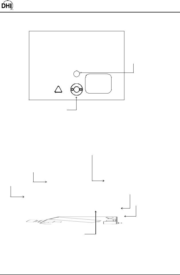
2.3.2.3SIDE VIEW
3
2
1
4
5
6, 7
1. |
Lo RPT Isolation Valve Control Knob |
5. |
TEST port (DH500 F) |
2. |
RPM3 A30000/A6000-AF Reference Pressure Monitor |
6. |
Electrical Power Connector (IEC320-C13) |
3. |
Lo RPT Pressure Relief Valve |
7. |
Foot switch (remote [ENTER]) connector |
4.Oil Collection Cup (from Relief Valve)
Figure 3. RPM3/HPMS Side View
©2000 DH Instruments, Inc. |
Page 8 |
RPM3/HPMS A30000/A6000-AF Operation and Maintenance Manual
2.3.3RPM3 FRONT AND REAR PANELS
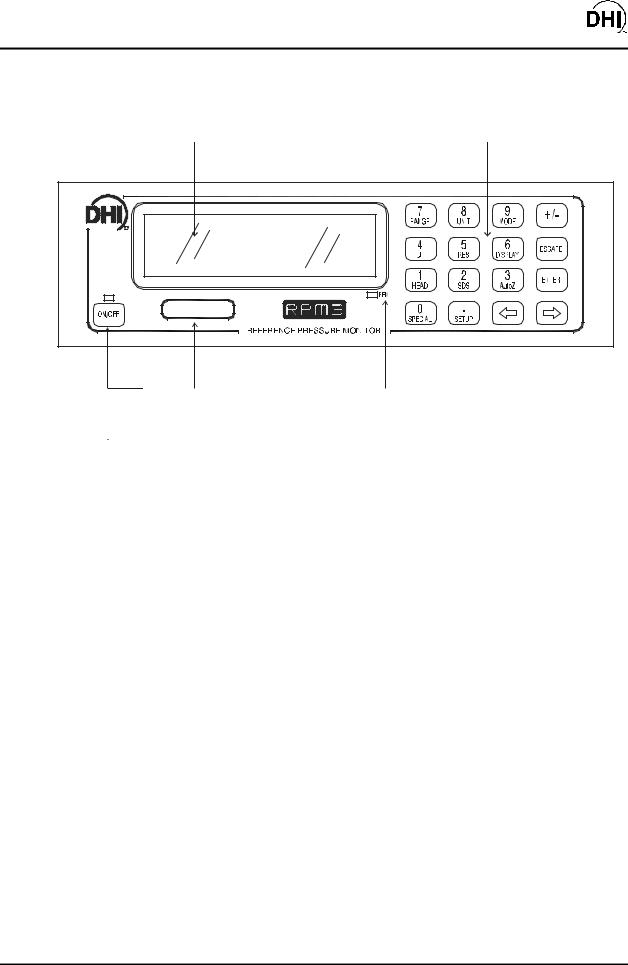
2.3.3.1FRONT PANEL
|
|
|
|
|
1 |
|
|
|
|
|
|
|
|
|
|
|
2 |
|
|
|
|
|
|
|
|||||||||||||||
|
|
|
|
|
|
|
|
|
|
|
|
|
|
|
|
|
|
|
|
|
|
|
|
|
|
|
|
|
|
|
|
|
|
|
|
|
|
|
|
|
|
|
|
|
|
|
|
|
|
|
|
|
|
|
|
|
|
|
|
|
|
|
|
|
|
|
|
|
|
|
|
|
|
|
|
|
|
|
|
|
|
|
|
|
|
|
|
|
|
|
|
|
|
|
|
|
|
|
|
|
|
|
|
|
|
|
|
|
|
|
|
|
|
|
|
|
|
|
|
|
|
|
|
|
|
|
|
|
|
|
|
|
|
|
|
|
|
|
|
|
|
|
|
|
|
|
|
|
|
|
|
|
|
|
|
|
|
|
|
|
|
|
|
|
|
|
|
|
|
|
|
|
|
|
|
|
|
|
|
|
|
|
|
|
|
|
|
|
|
|
|
|
|
|
|
|
|
|
|
|
|
|
|
|
|
|
|
|
|
|
|
|
|
|
|
|
|
|
|
5 |
|
|
4 |
|
|
3 |
|
|
|
||||
1. |
Display |
4. |
RPT designator label |
|||
2. |
Multi-Function Keypad |
5. |
Soft ON/OFF key and indicator |
|||
3.Remote Indicator
Figure 4. RPM3 Front Panel
Page 9 |
©2000 DH Instruments, Inc. |
RPM3/HPMS A30000/A6000-AF Operation and Maintenance Manual
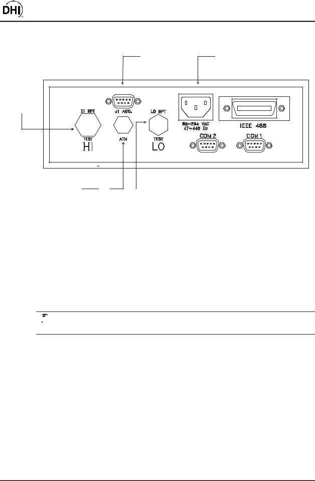
2.3.3.2REAR PANEL
|
|
1 |
2 |
6 |
|
|
|
5 |
4 |
3 |
|
1. |
Accessories Connection Cable (connects to HPMS |
4. |
ATM Post (On-Board Barometer) |
|
Rear panel FOOT SWITCH and HPMS LEDs) |
|
(10-32 UNF) |
2. |
Electrical Power Connector (IEC320-C13) |
5. |
Label, Product (on bottom of case) |
3. |
LO TEST Port (A5000 RPT) (1/8 in. NPT F) |
6. |
HI TEST Port (A30000 RPT) (DH500 F) |
Figure 5. RPM3 Rear Panel
2.3.4POWER CONNECTION
•Connect the power cable to the RPM3 rear panel electrical power connector.
•Do NOT connect the other end of the power cable to a power source yet.


 RPM3 is always powered and active when power is supplied through the rear panel power connector. The front panel ON/OFF key controls a soft ON/OFF (see Section 3.1.4).
©2000 DH Instruments, Inc. |
Page 10 |
RPM3/HPMS A30000/A6000-AF Operation and Maintenance Manual
2.3.5FOOT SWITCH CONNECTION
Connect the foot switch supplied in the RPM3/HPMS accessories to the HPMS rear panel electrical connection labeled FOOT SWITCH. Place the foot switch on the floor at a convenient location. The FOOT SWITCH function is equivalent to the RPM3 front panel [ENTER] key and may be used frequently while running tests and calibrations.
2.3.6TEST PORT CONNECTION
A single high pressure TEST port is provided on the rear panel of the HPMS.
The test port connection is a DH500 F. DH500 is a gland and collar type fitting for 1/4 in. (6 mm) coned and left hand threaded tube. DH500 is equivalent to AE F250C, HIP HF4, etc.
Connection to OPG1 if the RPM3/HPMS is Part of an HGC-30000-AF System
If the RPM3/HPMS was delivered as part of an HGC-30000-AF Hydraulic Gauge Calibrator, an OPG1 Oil Pressure Generator/Controller was delivered with it. The OPG1 includes a fittings kit with the necessary fittings to interconnect the RPM3/HPMS and OPG1 and instructions on making the connection. See the OPG1-30000-AF manual.

 USE THE CORRECT PRESSURE CONNECTORS: The RPM3/HPMS TEST port fitting is a DH500 F (see Section 1.2.1). It is NOT a 1/8 in. NPT F. Never use fittings other than the corresponding male fittings in these connectors. Damage to the connectors and dangerous failure under pressure could result from using incorrect fittings.

 DO NOT APPLY PRESSURE UNTIL YOU ARE FAMILIAR WITH OPERATION: The RPM3/HPMS rear panel test port connects internally to both the RPM3’s 6 000 psi (40 MPa) and 30 000 psi (200 MPa)RPTs. The valve on the front of the HPMS isolates the low pressure RPT when the high pressure RPT is in use. Do not apply pressure to the RPM3/HPMS until you are familiar with its operation and know how to protect the low pressure RPT from overpressure (see Section 3.1.8). FAILURE TO PROTECT THE LOW PRESSURE RPT FROM OVERPRESSURE MAY DESTROY IT. DAMAGE DUE TO RPT OVERPRESSURE IS NOT COVERED BY THE PRODUCT WARRANTY.
2.3.6.1THE RPM3 ATM PORT
The ATM pass through on the RPM3 rear panel is connected to the RPM3’s onboard barometer. This connection assures that the on-board barometer measures ambient atmospheric pressure rather than the pressure inside the RPM3 case that may vary slightly from ambient pressure. The ATM port should be left open and unobstructed.

 NEVER plug or obstruct the ATM pass through as this may adversely affect gauge mode operation and autozeroing on an absolute transducer.
Page 11 |
©2000 DH Instruments, Inc. |

RPM3/HPMS A30000/A6000-AF Operation and Maintenance Manual
2.3.7SETTING UP FILE SEQUENCES
RPM3 supports automated test/calibration sequences. Sequence parameters for testing specific DUTs can be stored in Sequence Files and recalled when a Sequence is run. Consider setting up Sequence Files for frequently tested DUTs as part of the RPM3 set up process (see Section 3.3.6).
2.4 POWER UP AND VERIFICATION
2.4.1APPLY POWER
Connect the RPM3 power cable to an electric supply of 85 to 264 VAC (47 to 440 Hz). Observe the front panel display as RPM3 initializes, error checks and goes to the main run screen (see Section 3.1.2). Check that one of the two green Valve Status LEDs on the front panel of the HPMS is lit (the red LED should NOT be ON).


 RPM3 is always powered and active when power is supplied through the rear panel power connector. The front panel ON/OFF key controls a soft ON/OFF function (see Section 3.1.4).
If the RPM3 fails to reach the main run screen, service is required. Record the sequence of operation and displays observed and contact a DHI Authorized Service Center (see Section 7.2, Table 18).
If neither of the green LEDs on the HPMS front panel lights, check that the 9-pin D-Sub accessory cable at the rear of the RPM3 itself is properly connected to the ACC. J1 connector.


 The active range on power up is the same as the range that was active at the last power down (see Section 3.1.6).
2.4.2CHECK PROPER PRESSURE MEASUREMENT OPERATION
2.4.2.1CHECKING ABSOLUTE MODE PRESSURE MEASUREMENT
Check that the RPM3 RPTs operate properly in absolute mode.
Open the RPM3/HPMS TEST port to atmosphere. Put the valve knob in the HPMS front panel into the Lo RPT Active position. This opens the Lo RPT to the HPMS TEST port.
Press [MODE] on the RPM3 and select absolute. Change the pressure unit of measure using [UNIT] if desired (see Section 3.2.3).
Observe the RPM3 indicated pressure. Check that the value is equal to atmospheric pressure ± 5 psi. Repeat this process for all the ranges on both RPTs using [RANGE] and [ENTER] to change ranges. Check that the values of atmospheric pressure measured by the different ranges agree with each other within RPM3 measurement tolerances (see Section 1.2.2.1). If they do NOT agree within
©2000 DH Instruments, Inc. |
Page 12 |

RPM3/HPMS A30000/A6000-AF Operation and Maintenance Manual
tolerances, RPM3 may need calibration or repair.
2.4.2.2CHECKING GAUGE MODE PRESSURE MEASUREMENT
Open the RPM3/HPMS TEST port to atmosphere. Put the valve knob in the HPMS front panel into the Lo RPT Active position. This opens the Lo RPT to the TEST port.
Press [MODE] on the RPM3 and select gauge. Change the pressure unit of measure using [UNIT] if desired (see Section 3.2.3).
The value indicated should be near zero (± 5 psi, 35 kPa). Wait two minutes and then press [AutoZ]. This runs AutoZ to zero the range (see Section 3.2.10). Upon return to the main run screen, observe that the indication of measured pressure has zeroed.
Use [RANGE] and [ENTER] to change ranges (see Section 3.2.2) and repeat the zeroing process for each range (the two minute wait does not need to be repeated each time).
If a range fails to zero properly, RPM3 may need repair.


 It is normal for RPM3 to indicate a value other than zero when vented when gauge mode is first entered or ranges are changed, especially if AutoZ is OFF, RPM3 has been OFF for some time, its location has changed or the fluid head to which it is connected has changed.
2.5 SHORT TERM STORAGE
The following is recommended for short term storage of RPM3/HPMS:
•Vent the RPM3/HPMS TEST port.
•Disconnect the power supply.
When RPM3 will NOT be used for some time, it may be left powered, but use the soft ON/OFF key to turn OFF the display.
2.6 LONG TERM STORAGE AND SHIPPING
The following is recommended for long term storage and or shipping of RPM3/HPMS:
•Plug the HPMS TEST port.
•Place the RPM3/HPMS in a plastic bag.
Place the RPM3/HPMS in the custom shipping/storage container in which it was delivered.
Page 13 |
©2000 DH Instruments, Inc. |

RPM3/HPMS A30000/A6000-AF Operation and Maintenance Manual
NOTES
©2000 DH Instruments, Inc. |
Page 14 |
RPM3/HPMS A30000/A6000-AF Operation and Maintenance Manual
3. OPERATION
3.1 GENERAL/MANUAL OPERATION
RPM3/HPMS is designed to offer the optimum balance between simple, straight forward operation and the availability of a wide variety of functions with a high level of operator discretion if desired.
The RPM3 provides the local operator interface is through a front panel 2 x 20 character alphanumeric display, a 4 x 4 multi-function keypad and an [ENTER] foot switch.
The HPMS mounts the RPM3 at a convenient viewing angle and includes a valve and visual indicators to isolate and protect the RPM3’s 6 000 psi RPT (Ranges L1, L2, L3) when using the 30 000 psi RPT (Ranges H1, H2, H3) (see Section 3.1.6).
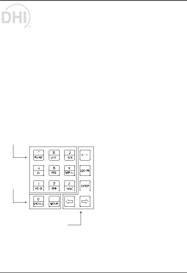
3.1.1KEYPAD LAYOUT AND PROTOCOL
The RPM3 has a 4 x 4 keypad and an [ENTER] footswitch for local operator access to direct functions, function menus and for data entry.
3
2
1
1.The Editing and Execution keys are for execution, suspending execution, backing up in menus and editing entries.
2.The Menu/Data keys provide access to function menus from the main run screen.
The menu |
name is on |
the bottom half of |
the key. |
The SETUP |
menu is for more |
frequently used functions (see Section 3.3). The SPECIAL menu is for functions that are NOT generally used as a part of day to day operation (see Section 3.4). These keys enter numerical values when editing.
3.The Function/Data keys allow very commonly used functions to be accessed directly from the main run screen by a single keystroke. The name of the function is on the bottom half of the key (see Section 3.2.1). These keys enter numerical values when editing.
4.[ENTER] Foot Switch (not shown) acts in exactly the same manner as the keypad [ENTER] key. It serves as a remote [ENTER] key to be used when the operator’s hands are occupied or touching the RPM3 front panel is not convenient.
Figure 6. RPM3 Keypad
Page 15 |
©2000 DH Instruments, Inc. |
RPM3/HPMS A30000/A6000-AF Operation and Maintenance Manual
Key press confirmation is provided by both tactile and audible feedback. A single tone confirms a valid entry, a descending two note tone signals an invalid entry. The audible valid entry feedback can be suppressed or modified by pressing [SPECIAL] and selecting <7Intern>, <2sound> (see Section 3.4.7.2).
Pressing the [ENTER] key or foot switch generally causes execution or forward movement in the menu tree.
Pressing the [ESCAPE] key moves back in the menu tree and/or causes execution to cease or suspend without changes being implemented. Pressing [ESCAPE] repeatedly eventually returns to the main run screen. From the main run screen, pressing [ESCAPE] allows momentary viewing of the RPM3 introduction screen.
Pressing the [+/-] key changes a numerical sign when editing. It also toggles through multiple screens when available.
Pressing the← [← ] and→ [→ ] keys allow reverse and forward cursor movement when editing data entry. These keys are also used to scroll through choices.


 Some screens go beyond the two lines provided by the display. This is indicated by a flashing arrow in the second line of the display. Use←[← ] and→[→ ] to move the cursor to access the lines that are NOT visible or directly enter the number of the hidden menu choice if you know it.
3.1.2MAIN RUN SCREEN
The RPM3 main run screen is its home display that is reached on power up and from which other functions and menus are accessed. It is the top level of all menu structures.
The main run screen is where the RPM3 is left in normal operation. It displays the current measured pressure as well as a variety of additional information if desired.
2 |
|
|
|
4 |
|
|
|
|
5 |
|
7 |
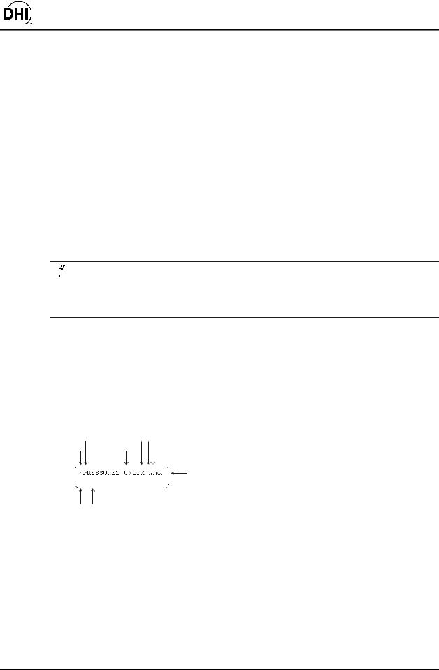
1. |
<•> Ready/Not Ready indication, <•> when Ready, |
|||||||||
|
|
|
|
|
|
|||||||||||||||||
1 |
|
|
|
|
3 |
|
|
|
|
|
|
6 |
||||||||||
|
|
|
|
|
|
|
|
|
|
|
|
|
|
|
|
|
|
|
<↑↑ > or <↓↓ > indicating direction of measured pressure |
|||
|
|
|
|
|
|
|
|
|
|
|
|
|
|
|
|
|
|
|
evolution when Not Ready (see Section 3.1.5). |
|||
|
|
|
|
|
|
|
|
|
|
|
|
|
|
|
|
|
|
|
||||
|
|
|
|
|
|
|
|
|
|
|
|
|
|
|
|
|
|
|
||||
|
|
|
D |
DISPLAY FUNCTION |
|
|
|
|
|
2. |
<PRESSURE1>: |
Numerical |
value and |
sign of |
||||||||
|
|
|
|
|
|
|
|
|
|
|
|
|
|
|
|
|
|
|
pressure measured by active RPT and range. Shows |
|||
|
|
|
|
|
|
|
|
|
|
|
|
|
|
|
|
|
|
|
||||
9 |
|
|
|
|
|
|
8 |
|
|
|
|
|
|
|
|
|
|
result of last |
average in |
average |
display |
|
|
|
|
|
|
|
|
|
|
|
|
|
|
|
|
|
mode (see Section 3.2.7.1). |
|
|
||||
|
|
|
|
|
|
|
|
|
|
|
|
|
||||||||||
|
|
|
|
|
|
|
|
|
|
|
|
|
|
|
|
|
|
|
|
|
||
|
|
|
|
|
|
|
|
|
|
|
|
|
|
|
|
|
|
3. |
<UNIT>: Current unit of measure (see Section 3.2.3). |
|||
4.<M>: Pressure measurement mode: <g> for gauge, <a> for absolute (see Section 3.2.4).
5.<h>: Indicates whether a head correction is applied. <h> if applied, blank if NOT (see Section 3.2.8).
6.<z>: Indicates whether the autozero function is ON or OFF. <z> if ON; blank if OFF (see Section 3.4.1).
7.<RR>: Indicates active RPT (<H> = high, <L> = low) and range (<1> = low, <2> = mid, <3> = hi) (see Section 3.2.2).
8.<DISPLAY FUNCTION>: Information displayed depends on current display function.
9.<D>: Indication of what is being displayed on the bottom line of the display as set by the DISPLAY function (see Section 3.2.7). Choices include:
•<σσ >: Current DISPLAY mode is average (see Section 3.2.7.1).
•<R>: Current DISPLAY mode is rate (see Section 3.2.7.2); or if <n avg> is in the bottom right hand corner of the display, current DISPLAY mode is average and this is the instantaneous reading average screen (see Section 3.2.7.1).
•<H>: Current DISPLAY mode is hi/lo (see Section 3.2.7.5).
©2000 DH Instruments, Inc. |
Page 16 |

RPM3/HPMS A30000/A6000-AF Operation and Maintenance Manual
•<D>: Current DISPLAY mode is deviation (see Section 3.2.7.3).
•< >, <↑↑ > or <↓↓ >: Current DISPLAY mode is RPT (see Section 3.2.7.4).
•<F>: Current DISPLAY mode is freeze (see Section 3.2.7.6).
•Blank, NO character: Current DISPLAY mode is clean (see Section 3.2.7.7).


 RPM3 has a screen saver function that causes the display to dim if NO key is pressed for 10 minutes. Pressing a key restores full power to the display. The screen saver activation time can be changed or screen saving can be completely suppressed (see Section 3.4.7.1).
3.1.3SOUNDS
RPM3 is equipped with a variable frequency tone device to provide audible feedback and alarms. The beeper is used for the following indications:
•Valid key press: Brief beep. Choice between three frequencies or NO sound is available (see Section 3.4.7.2).
• Invalid key press or out of tolerance reading when running an automated test sequence: Descending two tone blurp (see Section 3.2.11.2).
•In tolerance reading when running an automated test sequence: Ascending three tone fanfare (see Section 3.2.11.2).
•Leak check routine completed: Three two second beeps (see Section 3.3.5).
•UL (upper limit) exceeded: Intermittent one second beeps (see Section 3.2.5).
•Pmax! (overpressure limit) exceeded: Eight second high frequency beep (see Section 3.2.5.1).
•Lo RPT is active but a Hi RPT range is selected: Intermittent two second high frequency beep. The audible alarm is combined with flashing of the red, Lo RPT Active LED on the HPMS (see Section 3.2.5.2).
3.1.4SOFT [ON/OFF] KEY
RPM3 is equipped with a soft [ON/OFF] key and indicator LED on the bottom left hand corner of the front panel. The purpose of the soft ON/OFF key is to put RPM3 into a dormant mode in which the display is turned OFF but power is still supplied and overpressure functions are still active. When RPM3 is ON, the ON/OFF indicator is ON continuously. When RPM3 is soft OFF, the ON/OFF indicator blinks every five seconds.
The soft [ON/OFF] key can also be used to reset from an overpressure condition (see Section 3.2.5.1).
When RPM3 is soft OFF, receiving a remote command turns it ON.
Page 17 |
©2000 DH Instruments, Inc. |

RPM3/HPMS A30000/A6000-AF Operation and Maintenance Manual
3.1.5PRESSURE READY <*>/NOT READY (<↑↑ > OR <↓↓ >) INDICATION
The character to the left of the measured pressure on the main run screen provides a pressure Ready <*>/Not Ready (<↓↓ > or <↑↑ >) indication. This indication is intended to provide the user with a clear and objective indication of when a stable pressure has been achieved. Ready <*> is indicated when the current stability (rate of change) of pressure is less than the stability limit. The user can set the stability limit (see Section 3.3.4). The Ready indication is often used when comparing the RPM3 and a test device to indicate when a valid reading can be made.
Ready <*>/Not Ready (<↓↓ > or <↑↑ >) character indications are:
•<*>: Pressure Ready (stable).
•<↓↓ >: Pressure Not Ready (unstable) and decreasing.
•<↑↑ >: Pressure Not Ready (unstable) and increasing.
3.1.6MULTIPLE PRESSURE RANGES
RPM3 A30000/A6000-AF has two reference pressure transducers (RPTs) each of which has three ranges for a total of six pressure ranges. This multi-ranging feature allows measurement uncertainty to be optimized for the range of pressure in which you are working. Generally, the best range to select (see Section 3.2.2) is that whose full scale is closest to, but greater than, the maximum pressure of the device or system under test.
RPM3 handles all of the data operations needed to make range changes occur transparently to the user when the RANGE function is used for range selection. For a range change to be executed, the current pressure applied to the RPT on which the range is being selected must be lower than the current upper limit (UL) of that range (see Section 3.2.5). The RPM3 Sequence feature automatically selects the most appropriate range based on the range of the device under test (see Section 3.2.11).
When the range is changed, the upper limit automatically changes to the default for that range or to the last upper limit set for that range. In addition, most other functions and settings are range specific (see Section 3.2.2).


 RPM3 A30000/A6000-AF has six ranges. In general, settings and operational adjustments are specific to the range currently in use, as if you had six instruments rather than one. The DISPLAY function, HEAD functions and AUTO READRT function are NOT range specific. In remote mode, most settings are RPT specific rather than range specific (see Section 4.3).
©2000 DH Instruments, Inc. |
Page 18 |

RPM3/HPMS A30000/A6000-AF Operation and Maintenance Manual
3.1.6.1RANGES AND IDENTIFICATION
The active RPT and range is continuously indicated in the upper right hand corner of the main run screen and most other screens.
Hi RPT: The A30000 RPT whose maximum range is 30 000 psi (200 MPa) is referred to as the Hi RPT.
Lo RPT: The A6000 RPT whose maximum range is 6 000 psi (40 MPa) is referred to as the Lo RPT.
Range 1, 2 or 3: The three ranges of each RPT are referred to as 1 = lo range, 2 = mid range, 3 = hi range. The Lo RPT ranges, low to high, are L1, L2, L3. The high PRT ranges, low to high, are H1, H2, H3.
Table 2. RPM3 Range Identification Summary
REFERENCE PRESSURE |
|
|
RANGE |
|
TRANSDUCER AND RANGE |
DESIGNATION |
DISPLAY SYMBOL * |
PSI (MPa) |
|
|
|
|
|
|
Lo RPT, Lo range |
Lo, 1 |
L1 |
2 000 |
(14) |
Lo RPT, Mid range |
Lo, 2 |
L2 |
4 000 |
(28) |
Lo RPT, Hi range |
Lo, 3 |
L3 |
6 000 |
(42) |
|
|
|
|
|
Hi RPT, Lo range |
Hi, 1 |
H1 |
10 000 (70) |
|
|
|
|
|
|
Hi RPT, Mid range |
Hi, 2 |
H2 |
18 000 |
(125) |
Hi RPT, Hi range |
Hi, 3 |
H3 |
30 000 |
(200) |
*The display symbol is included in the upper, right hand corner of most RPM3 menu displays as a convenient indicator of active range.
3.1.7AUTOMATED TEST/CALIBRATION SEQUENCES
The RPM3 SEQUENCE function supports “quick” and “file” automated calibration sequences. These automatically set the appropriate RPM3 range, resolution and stability limit based on the characteristics of the device under test. They also prompt the user through the increments of the calibration sequence and log calibration data. The SEQUENCE function should be used for most common calibration tasks, especially calibration of analog pressure gauges (see Section 3.2.11).
Page 19 |
©2000 DH Instruments, Inc. |

RPM3/HPMS A30000/A6000-AF Operation and Maintenance Manual
3.1.8HPMS (HIGH PRESSURE MOUNTING SYSTEM)
The HPMS (high pressure mounting system) holds the RPM3 at a convenient viewing angle and includes a valve and visual indicators to isolate and protect the RPM3’s 6 000 psi RPT (Ranges L1, L2, L3) when using the 30 000 psi RPT (Ranges H1, H2, H3).
mOPERATION
Numerical references in this Section refer to Figure 1.
In normal use, the operator’s only interaction with the HPMS is to operate the isolation valve knob to connect and disconnect the Lo RPT from the TEST port. The valve’s operation is prompted by the Valve Position LEDs (1, 3).
The Lo RPT isolation valve (2) isolates and protects the Lo RPT from the TEST port when it is closed (knob fully CCW) and opens the Lo RPT to the TEST port when it is open (knob fully CW).
The Valve Position LEDs (1, 3) indicate the position in which the valve knob should be set based on the current range selection on the RPM3. If a range on the Hi RPT (H1, H2 or H3) is selected, the LO RPT SHUT OFF LED (1) is lit indicating that the valve knob should be turned fully CW to close the valve, protecting the Lo RPT from high pressure. If a range on the Lo RPT (L1, L2 or L3) is selected, the LO RPT ACTIVE LED (3) is lit indicating that the valve knob should be turned fully CCW to open the valve, connecting the Lo RPT to the test pressure.


 The HPMS isolation valve (2) must always be in the closed position (knob fully CCW) when operating at pressure greater than 6 000 psi (40 MPa).
The CAUTION LO RPT ACTIVE LED (4) is used to indicate that the Lo RPT is active and provide a warning when the Lo RPT is active but a Hi RPT range is selected on the RPM3.
The CAUTION LO RPT ACTIVE LED (4) is driven by the value of pressure currently measured by the Lo RPT, it is not driven by the valve position as there is no sensing of the valve position.
The CAUTION LO RPT ACTIVE LED (4) has three possible conditions:
•LED is OFF: The Lo RPT is NOT active. The Lo RPT is considered active when it measures a pressure greater than 30 psig (200 kPa).
•LED ON continuously: The Lo RPT IS active and a Lo RPT range is selected on the RPM3. The LED is lit as a reminder that the Lo RPT is active and pressure over its maximum working pressure of 6 600 (46 MPa) should not be applied.
•LED is flashing on accompanied by high frequency beeps and <!!!LO RPT ACTIVE!!!> displayed by RPM3: Lo RPT IS active and a Hi RPT range is selected on RPM3. The Lo RPT should NOT be active when a Hi RPT range is in use.
Hi RPT ranges will overpressure and damage the Lo RPT.
©2000 DH Instruments, Inc. |
Page 20 |
Loading...