


®
87 & 89 Series IV
True RMS Multimeter
Service Manual
PN 676137
May 1999
© 1999 Fluke Corporation, All rights reserved. Printed in U.S.A. All product names are trademarks of their respective companies.
Limited Warranty & Limitation of Liability
Fluke Corporation (Fluke) warrants this product to be free from defects in material and workmanship under normal use and service for the life of the product. This warranty extends only to the original buyer or end-user customer of a Fluke authorized reseller, and does not apply to fuses, batteries or to any product which, in Fluke’s opinion, has been misused, altered, neglected or damaged by accident or abnormal conditions of operation or handling. Fluke warrants that software will operate on appropriate Fluke instruments substantially in accordance with its functional specifications for 90 days and that it has been properly recorded on non-defective media. Fluke does not warrant that software will be error free or operate without interruption.
Fluke authorized resellers shall extend this warranty on new and unused products to end-user customers only but have no authority to extend a greater or different warranty on behalf of Fluke.
Fluke's warranty obligation is limited, at Fluke's option, to refund of the purchase price, or free of charge repair or replacement of a defective product which is returned to a Fluke authorized service center within the warranty period.
To obtain warranty service, contact your nearest Fluke authorized service center or send the product, with a description of the difficulty, postage and insurance prepaid (FCA Destination), to the nearest Fluke authorized service center. Fluke assumes no risk for damage in transit. Following warranty repair, the product will be returned to Buyer, transportation prepaid (FCA Destination). If Fluke determines that the failure was caused by misuse, alteration, accident or abnormal condition of operation or handling, Fluke will provide an estimate of repair costs and obtain authorization before commencing the work. Following repair, the product will be returned to the Buyer transportation prepaid and the Buyer will be billed for the repair and return transportation charges (FCA Shipping Point).
Warranty service is available outside the United States only if product was purchased through a Fluke Authorized Sales Outlet in the country of use or the applicable Fluke international price was paid. Product transported from the United States for which the applicable Fluke international price was not paid must be returned to the U.S. to receive warranty service, at the shipment expense and risk of Buyer. Fluke reserved the right to invoice Buyer for importation costs of repair/replacement parts when product purchased in one country is submitted for repair in another country.
THIS WARRANTY IS PURCHASER’S SOLE AND EXCLUSIVE REMEDY AND IS IN LIEU OF ALL OTHER WARRANTIES, EXPRESS OR IMPLIED, INCLUDING BUT NOT LIMITED TO ANY IMPLIED WARRANTY OF MERCHANTABILITY OR FITNESS FOR A PARTICULAR PURPOSE. FLUKE SHALL NOT BE LIABLE FOR ANY SPECIAL, INDIRECT, INCIDENTAL OR CONSEQUENTIAL DAMAGES OR LOSSES, INCLUDING LOSS OF DATA, WHETHER ARISING FROM BREACH OF WARRANTY OR BASED ON CONTRACT, TORT, RELIANCE OR ANY OTHER THEORY.
Since some countries or states do not allow limitation of the term of an implied warranty, or exclusion or limitation of incidental or consequential damages, the limitations and exclusions of this warranty may not apply to every buyer. If any provision of this Warranty is held invalid or unenforceable by a court of competent jurisdiction, such holding will not affect the validity or enforceability of any other provision.
To locate an authorized service center, visit us on the World Wide Web at www.fluke.com or call Fluke using the phone numbers listed below:
1-888-99-FLUKE (1-888-993-5853) in USA and Canada +31 402-678-200 in Europe
+81-3-3434-0181 Japan
+65-738-5655 Singapore +1-425-356-5500 in other countries
Fluke Corporation |
Fluke Europe B.V. |
P.O. Box 9090 |
P.O. Box 1186 |
Everett WA 98206-9090 |
5602 B.D. |
U.S.A |
Eindhoven, The Netherlands |
Table of Contents
Title |
Page |
Introduction ...................................................................................................... |
1 |
Precautions and Safety Information.................................................................. |
2 |
International Symbols ....................................................................................... |
2 |
Safety Information ............................................................................................ |
3 |
Specifications.................................................................................................... |
4 |
Accuracy ...................................................................................................... |
4 |
Feature Summary ......................................................................................... |
4 |
General Specifications.................................................................................. |
5 |
Basic Specifications...................................................................................... |
6 |
AC Voltage and Decibel Specifications ....................................................... |
6 |
AC Current Specifications............................................................................ |
7 |
DC Current Specifications............................................................................ |
7 |
Resistance and Conductance Specifications ................................................. |
8 |
Capacitance and Diode Function Specifications .......................................... |
8 |
Frequency, Duty Cycle, & Pulse Width Specifications................................ |
8 |
Temperature Specifications .......................................................................... |
9 |
MIN MAX Recording Specifications ........................................................... |
9 |
Frequency Counter Sensitivity ..................................................................... |
9 |
Burden Voltage (A, mA, μA) ....................................................................... |
10 |
Input Characteristics..................................................................................... |
10 |
Required Equipment ......................................................................................... |
11 |
Basic Maintenance............................................................................................ |
12 |
Opening the Meter Case ............................................................................... |
12 |
Removing and Reinserting the Circuit Board Assembly .............................. |
12 |
Replacing the LCD ....................................................................................... |
13 |
Reassembling the Meter Case....................................................................... |
14 |
Testing Fuses (F1 and F2) ............................................................................ |
14 |
Replacing Fuses............................................................................................ |
15 |
Replacing the Batteries................................................................................. |
15 |
Cleaning ....................................................................................................... |
16 |
Performance Tests ............................................................................................ |
17 |
Testing the Display....................................................................................... |
17 |
Backlight Test .............................................................................................. |
17 |
Current Terminal Sensing Test..................................................................... |
17 |
Keypad Test.................................................................................................. |
18 |
Verification of the IR Communication Port ................................................. |
18 |
i

87 & 89 Series IV
Service Information
Testing Temperature..................................................................................... |
18 |
Testing Voltage, Current, Resistance, Capacitance and Diode Functions .... |
19 |
Calibration ........................................................................................................ |
22 |
Keypad Interface .......................................................................................... |
22 |
General Procedure ........................................................................................ |
23 |
Special Requirements ................................................................................... |
24 |
Calibration Inputs ......................................................................................... |
24 |
Remote Interface .......................................................................................... |
26 |
Temperature Calibration............................................................................... |
26 |
Setup ........................................................................................................ |
26 |
Procedure ................................................................................................. |
27 |
Re-Programming Serial Number or Model Number .................................... |
27 |
Parts and Accessories ....................................................................................... |
28 |
ii
List of Tables
Table |
Title |
Page |
1. |
International Symbols ........................................................................................... |
2 |
2. |
Required Tools and Equipment............................................................................. |
11 |
3. |
Temperature Test Input and Display ..................................................................... |
18 |
4. |
Performance Test Steps......................................................................................... |
19 |
5. |
Calibration Inputs.................................................................................................. |
24 |
6. |
Replacement Parts and Accessories ...................................................................... |
28 |
iii

87 & 89 Series IV
Service Information
iv
List of Figures
Figure |
Title |
Page |
1. |
Removing LCD Mask to Access LCD .................................................................. |
13 |
2. |
Testing the Current Fuses...................................................................................... |
15 |
3. |
Battery and Fuse Replacement.............................................................................. |
16 |
4. |
Display Test .......................................................................................................... |
17 |
5. |
Locating Recessed Calibration Button .................................................................. |
22 |
6. |
Calibration Display ............................................................................................... |
23 |
7. |
Replacement Parts and Accessories ...................................................................... |
29 |
v

87 & 89 Series IV
Service Information
vi
Introduction
 Warning
To avoid shock or injury, do not perform the verification tests or calibration procedures described in this manual unless you are qualified to do so.
The information provided in this document is for the use of qualified personnel only.
Caution
The 87 & 89 Series IV Multimeters contain parts that can be damaged by static discharge.
Follow the standard practices for handling static sensitive devices.
The information in this manual deals with the Fluke Models 87 & 89 Series IV True RMS Multimeters, (hereafter referred to as “the meter”). Information provided includes:
∙Precautions and safety information
∙Specifications
∙Basic maintenance (cleaning, replacing the battery and fuses)
∙Performance test procedures
∙Calibration and calibration adjustment procedures
∙Accessories and replaceable parts
For complete operating instructions, refer to the Model 87 & 89 Series IV Users Manual.
To contact Fluke, call:
1-888-993-5853 in USA and Canada
+31 402-678-200 in Europe
+81-3-3434-0181 Japan
+65-738-5655 Singapore
+1-425-356-5500 in other countries
For additional information about Fluke, its products and services, visit Fluke’s web site at:
www.fluke.com
1
87 & 89 Series IV
Service Manual
Precautions and Safety Information
Use the Meter only as described in the Users Manual. If you do not do so, the protection provided by the Meter may be impaired.
Read the “Safety Information” page before servicing this product.
In this manual, a Warning identifies conditions and actions that pose hazard(s) to the user; a Caution identifies conditions and actions that may damage the Meter or the test instruments.
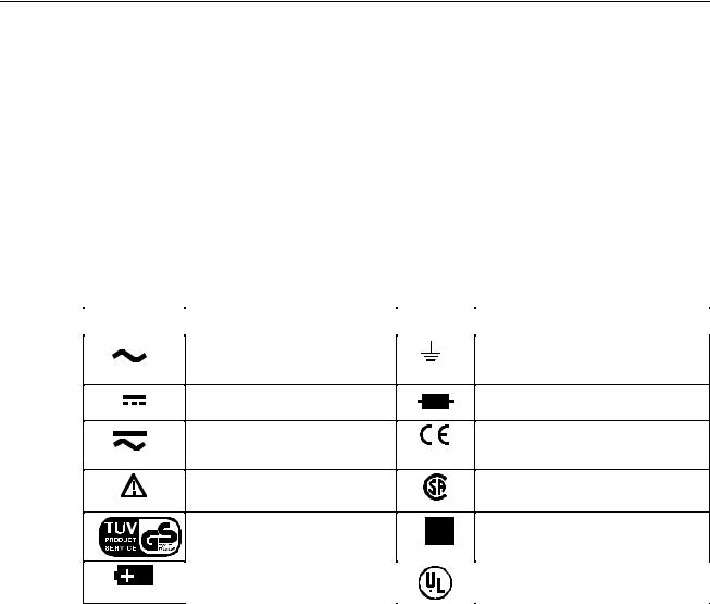
International Symbols
International symbols used on the Meter and in this manual are explained in Table 1.
Table 1. International Symbols
Symbol |
Meaning |
Symbol |
Meaning |
|
|
|
|
Alternating current
Direct current
Alternating or direct current
Refer to the manual. Important information.
Inspected and licensed by TÜV Product Services.
Earth ground
Fuse
Conforms to European Union directives
Conforms to relevant Canadian Standards Association directives
Double insulated
Battery |
|
Underwriters Laboratories, Inc. |
|
|
|
2
Safety Information
Safety Information
 Warnings and Precautions
To avoid possible electric shock or personal injury, follow these guidelines:
∙Do not use the Meter if it is damaged. Before you use the Meter, inspect the case. Look for cracks or missing plastic. Pay particular attention to the insulation surrounding the connectors.
∙Inspect the test leads for damaged insulation or exposed metal. Check the test leads for continuity. Replace damaged test leads before you use the Meter.
∙Do not use the Meter if it operates abnormally. Protection may be impaired. When in doubt, have the Meter serviced.
∙Do not operate the Meter around explosive gas, vapor, or dust.
∙Do not apply more than the rated voltage, as marked on the Meter, between terminals or between any terminal and earth ground.
∙Before use, verify the Meter’s operation by measuring a known voltage.
∙When measuring current, turn off circuit power before connecting the Meter in the circuit. Remember to place the Meter in series with the circuit.
∙When servicing the Meter, use only specified replacement parts.
∙Use caution when working above 30 V ac rms, 42 V peak, or 60 V dc. Such voltages pose a shock hazard.
∙Avoid working alone.
∙When using the probes, keep your fingers behind the finger guards on the probes.
∙Connect the common test lead before you connect the live test lead. When you disconnect test leads, disconnect the live test lead first.
∙Remove test leads from the Meter before you open the battery door.
∙Do not operate the Meter with the battery door or portions of the cover removed or loosened.
∙To avoid false readings, which could lead to possible electric shock or personal injury, replace the batteries as soon as the low battery indicator ( ) appears.
∙Use only type AA batteries, properly installed in the Meter case, to power the Meter.
Caution
To avoid possible damage to the Meter or to the equipment under test, follow these guidelines:
∙Disconnect circuit power and discharge all high-voltage capacitors before testing resistance, continuity, diodes, or capacitance.
∙Use the proper terminals, function, and range for your measurements.
∙Before measuring current, check the Meter's fuses and turn power OFF to the circuit before connecting the Meter to the circuit.
3

87 & 89 Series IV
Service Manual
Specifications
Accuracy
Accuracy is specified for a period of one year after calibration, at 18 °C to 28 °C (64 °F to 82 °F), with relative humidity to 90 %. Accuracy specifications are given as:
± ( [ % of reading ] + [ number of least significant digits ] )
AC mV, AC V, AC µA, AC mA, and AC A specifications are ac-coupled, true rms and are valid from 5 % of range to 100 % of range. AC crest factor can be up to 3.0 at full-scale, 6.0 at half-scale, except the 3000 mV and 1000 V ranges where it is 1.5 at full scale, 3.0 at halfscale.
Feature Summary
Feature
Dual Digital Displays
Analog Bar Graph
Backlight with 2 brightness adjustment
Fast Autorange
AC+DC true rms, ac rms specified to 100 kHz
dBm, dBV
AutoHOLD
Continuity / Open test
Fast Bar Graph
Duty cycle / Pulse width
MIN MAX Mode
FAST MN MX with 24-hour time stamp
Close-Case Calibration
Battery / Fuse Access Door
Hi-Impact Overmolded Case
|
Description |
Primary: |
50,000 counts |
Secondary: |
5,000 count |
Bar graph: |
51 segments, updates 40 times/second |
Bright-white backlight for clear readings in poorly lighted areas
Meter automatically selects best range
Choices for AC only, AC and DC dual display, or AC+DC readings
User-selectable impedance references for dBm
Holds readings on display
Beeper sounds for resistance readings below threshold, or to indicate a momentary open circuit
51 segments for peaking and nulling
Measure the time signal is on or off in % or milliseconds
Record maximum, minimum, and average values. 24-hour clock for MAX or MIN, elapsed time for AVG.
FAST MN MX captures peaks to 250 μsec.
No internal adjustments needed
Battery or fuse replaceable without voiding calibration
Protective holster features
4
 Loading...