


 Loading...
®
DSP-100/2000
LAN CableMeter®/Cable Analyzer
Users Manual
PN 642964 January 1997
© 1997 Fluke Corporation. All rights reserved. Printed in U.S.A. All product names are trademarks of their respective companies.
LIMITED WARRANTY & LIMITATION OF LIABILITY
Each Fluke product is warranted to be free from defects in material and workmanship under normal use and service. The warranty period is one year and begins on the date of shipment. Parts, product repairs and services are warranted for 90 days. This warranty extends only to the original buyer or end-user customer of a Fluke authorized reseller, and does not apply to fuses, disposable batteries or to any product which, in Fluke’s opinion, has been misused, altered, neglected or damaged by accident or abnormal conditions of operation or handling. Fluke warrants that software will operate substantially in accordance with its functional specifications for 90 days and that it has been properly recorded on non-defective media. Fluke does not warrant that software will be error free or operate without interruption.
Fluke authorized resellers shall extend this warranty on new and unused products to end-user customers only but have no authority to extend a greater or different warranty on behalf of Fluke. Warranty support is available if product is purchased through a Fluke authorized sales outlet or Buyer has paid the applicable international price. Fluke reserves the right to invoice Buyer for importation costs of repair/replacement parts when product purchased in one country is submitted for repair in another country.
Fluke’s warranty obligation is limited, at Fluke’s option, to refund of the purchase price, free of charge repair, or replacement of a defective product which is returned to a Fluke authorized service center within the warranty period.
To obtain warranty service, contact your nearest Fluke authorized service center or send the product, with a description of the difficulty, postage and insurance prepaid (FOB Destination), to the nearest Fluke authorized service center. Fluke assumes no risk for damage in transit. Following warranty repair, the product will be returned to Buyer, transportation prepaid (FOB Destination). If Fluke determines that the failure was caused by misuse, alteration, accident or abnormal condition of operation or handling, Fluke will provide an estimate of repair costs and obtain authorization before commencing the work. Following repair, the product will be returned to the Buyer transportation prepaid and the Buyer will be billed for the repair and return transportation charges (FOB Shipping Point).
THIS WARRANTY IS BUYER’S SOLE AND EXCLUSIVE REMEDY AND IS IN LIEU OF ALL OTHER WARRANTIES, EXPRESS OR IMPLIED, INCLUDING BUT NOT LIMITED TO ANY IMPLIED WARRANTY OF MERCHANTABILITY OR FITNESS FOR A PARTICULAR PURPOSE. FLUKE SHALL NOT BE LIABLE FOR ANY SPECIAL, INDIRECT, INCIDENTAL OR CONSEQUENTIAL DAMAGES OR LOSSES, INCLUDING LOSS OF DATA, WHETHER ARISING FROM BREACH OF WARRANTY OR BASED ON CONTRACT, TORT, RELIANCE OR ANY OTHER THEORY.
Since some countries or states do not allow limitation of the term of an implied warranty, or exclusion or limitation of incidental or consequential damages, the limitations and exclusions of this warranty may not apply to every buyer. If any provision of this Warranty is held invalid or unenforceable by a court of competent jurisdiction, such holding will not affect the validity or enforceability of any other provision.
Fluke Corporation |
Fluke Europe B.V. |
P.O. Box 9090 |
P.O. Box 1186 |
Everett, WA 98206-9090 |
5602 BD Eindhoven |
U.S.A. |
The Netherlands |
5/94
Table of Contents
Chapter |
Page |
|
1 |
Introduction ...................................................................................... |
1-1 |
|
Overview of Features ...................................................................................... |
1-1 |
|
Standard Accessories ...................................................................................... |
1-3 |
|
Using This Manual .......................................................................................... |
1-5 |
2 |
Getting Started ................................................................................. |
2-1 |
|
WSafety and Operational Information .......................................................... |
2-1 |
|
Quick Start....................................................................................................... |
2-3 |
|
Quick Configuration........................................................................................ |
2-4 |
|
Results within Accuracy Range ...................................................................... |
2-6 |
|
Autotest on Twisted Pair Cable ...................................................................... |
2-7 |
|
Autotest on Coaxial Cable .............................................................................. |
2-10 |
|
Main Unit Features.......................................................................................... |
2-12 |
|
Remote Features .............................................................................................. |
2-14 |
|
Strap and Bail .................................................................................................. |
2-16 |
|
Rotary Switch.................................................................................................. |
2-16 |
|
Turning On the Test Tool................................................................................ |
2-20 |
|
Configuring the Test Tool ............................................................................... |
2-22 |
|
Remote Lights, Messages, and Audible Tones ............................................... |
2-29 |
|
Remote End Testing ........................................................................................ |
2-30 |
|
Remote Communication Error ........................................................................ |
2-31 |
|
Battery Status .................................................................................................. |
2-31 |
3 |
Autotest ............................................................................................ |
3-1 |
|
Autotest Softkeys ............................................................................................ |
3-1 |
|
Autotest on Twisted Pair Cable ...................................................................... |
3-2 |
|
Link Performance Grade Result (Headroom) ................................................. |
3-4 |
|
Automatic Diagnostics (Model DSP-2000) .................................................... |
3-4 |
|
Autotest Results for Twisted Pair Cable ......................................................... |
3-6 |
i

DSP-100/2000
Users Manual
|
Autotest on Coaxial Cable .............................................................................. |
3-19 |
|
Autotest Results for Coaxial Cable ................................................................ |
3-21 |
|
Saving Autotest Results .................................................................................. |
3-23 |
|
The Autotest Report........................................................................................ |
3-25 |
4 |
Running Individual Tests ................................................................ |
4-1 |
|
Single Tests for Twisted Pair Cable ............................................................... |
4-1 |
|
Scanning Function .......................................................................................... |
4-2 |
|
When to Use a Remote Unit ........................................................................... |
4-2 |
|
The TDX Analyzer ......................................................................................... |
4-6 |
|
The TDR Test ................................................................................................. |
4-9 |
|
Single Test Results for Twisted Pair Cable .................................................... |
4-12 |
|
Single Tests for Coaxial Cable ....................................................................... |
4-14 |
|
Monitoring Network Activity ......................................................................... |
4-16 |
|
Identifying Hub Port Connections .................................................................. |
4-20 |
|
Monitoring Impulse Noise .............................................................................. |
4-20 |
|
Determining Hub Port Capabilities (Model DSP-2000)................................. |
4-23 |
|
Using the Tone Generator (Model DSP-2000) ............................................... |
4-24 |
5 |
Viewing and Printing Saved Reports.............................................. |
5-1 |
|
Printing Test Reports ...................................................................................... |
5-1 |
|
Viewing, Renaming, and Deleting Test Reports ............................................ |
5-6 |
6 |
Calibrations and Custom Test Standards ...................................... |
6-1 |
|
Calibrating the Test Tool ................................................................................ |
6-1 |
|
NVP Calibration ............................................................................................. |
6-3 |
|
Configuring a Custom Cable .......................................................................... |
6-4 |
7 |
Basic Cable Testing......................................................................... |
7-1 |
|
LAN Cable Construction ................................................................................ |
7-1 |
|
Attenuation ..................................................................................................... |
7-5 |
|
Noise .............................................................................................................. |
7-6 |
|
Characteristic Impedance................................................................................ |
7-7 |
|
Crosstalk and Near-End Crosstalk (NEXT) ................................................... |
7-9 |
|
Nominal Velocity of Propagation (NVP) ....................................................... |
7-14 |
|
Time Domain Reflectometry (TDR)............................................................... |
7-15 |
|
ACR .............................................................................................................. |
7-19 |
|
RL .............................................................................................................. |
7-20 |
|
Troubleshooting Basics .................................................................................. |
7-21 |
8 |
Maintenance and Specifications..................................................... |
8-1 |
|
Maintenance.................................................................................................... |
8-1 |
|
If the Test Tool Fails ...................................................................................... |
8-4 |
|
Specifications.................................................................................................. |
8-7 |
ii
|
|
Contents (continued) |
Appendices |
|
|
A |
Using DSP-LINK ................................................................................. |
A-1 |
B |
Glossary................................................................................................ |
B-1 |
C |
Tests Run per Test Standard During an Autotest................................. |
C-1 |
Index
iii

DSP-100/2000
Users Manual
iv
List of Tables
Table |
|
Page |
2-1. |
International Electrical Symbols................................................................. |
2-1 |
2-2. |
Key Functions for the Menu System .......................................................... |
2-3 |
2-3. |
Quick Configuration Settings ..................................................................... |
2-4 |
2-4. |
Main Unit Features ..................................................................................... |
2-13 |
2-5. |
Remote Connectors and Features ............................................................... |
2-15 |
2-6. |
Status Indications from Remotes ................................................................ |
2-29 |
2-7. |
Battery Status Messages ............................................................................. |
2-31 |
3-1. |
Wire Map Displays ..................................................................................... |
3-6 |
3-2. |
Items on the Attenuation Results Screen .................................................... |
3-10 |
3-3. |
Items on the Attenuation Plot Screen ......................................................... |
3-11 |
3-4. |
Items on the NEXT Results Screen ............................................................ |
3-12 |
3-5. |
Items on the NEXT Plot Screen.................................................................. |
3-13 |
3-6. |
Items on the ACR Results Screen ............................................................... |
3-15 |
3-7. |
Items on the ACR Plot Screen .................................................................... |
3-16 |
3-8. |
Items on the RL Results Screen .................................................................. |
3-17 |
3-9. |
Items on the RL Plot Screen ....................................................................... |
3-18 |
3-10. |
Items on the Autotest Save Screen.............................................................. |
3-24 |
4-1. |
Remote Requirements for Cable Tests ....................................................... |
4-3 |
4-2. |
Items on the TDX Analyzer Results Screen ............................................... |
4-7 |
4-3. |
Items on a TDX Analyzer Plot.................................................................... |
4-8 |
4-4. |
Effects of Termination on TDR Results ..................................................... |
4-9 |
4-5. |
Items on the TDR Results Screen (Twisted Pair Results) .......................... |
4-11 |
4-6. |
Items on the TDR Plot (Twisted Pair Results) ........................................... |
4-12 |
4-7. |
Items on the Traffic Monitor Screen........................................................... |
4-19 |
4-8. |
Items on the Noise Monitor Screen ............................................................ |
4-23 |
7-1. |
Identifying Cable Faults.............................................................................. |
7-22 |
8-1. |
Troubleshooting the Test Tool.................................................................... |
8-5 |
8-2. |
Replacement Parts....................................................................................... |
8-6 |
8-3. |
Characteristic Impedance Test Specifications ............................................ |
8-8 |
8-4. |
Length Test Specifications ......................................................................... |
8-9 |
8-5. |
Length Test Specifications ......................................................................... |
8-9 |
v

DSP-100/2000
Users Manual
8-6. |
Distance Specifications for TDR Test........................................................ |
8-11 |
8-7. |
PC Interface Cable Connections................................................................. |
8-13 |
8-8. |
9-to 25-pin Adapter .................................................................................... |
8-13 |
8-9. |
Certifications .............................................................................................. |
8-16 |
A-1. |
Summary of DSP-LINK Functions ............................................................ |
A-5 |
A-2. |
Special Terms Used in DSP-LINK............................................................. |
A-6 |
A-3. |
Formats for Uploaded Reports ................................................................... |
A-7 |
C-1. |
Tests Run per Test Standard During an Autotest....................................... |
C-2 |
vi
List of Figures
Figure |
|
Page |
1-1. |
Standard Accessories .................................................................................. |
1-4 |
2-1. |
The Asterisk and Test Tool Accuracy ........................................................ |
2-6 |
2-2. |
Autotest Connections for Twisted Pair Cable (Channel) ........................... |
2-8 |
2-3. |
Autotest Connections for Coaxial Cable .................................................... |
2-11 |
2-4. |
Main Unit Features ..................................................................................... |
2-12 |
2-5. |
Standard and Smart Remote Features ......................................................... |
2-14 |
2-6. |
Attaching the Strap and Opening the Bail .................................................. |
2-16 |
3-1. |
Autotest Connections for Twisted Pair Cable (Basic Link) ....................... |
3-2 |
3-2. |
Examples of Automatic Diagnostics Displays............................................ |
3-5 |
3-3. |
The Attenuation Plot Screen ....................................................................... |
3-11 |
3-4. |
The NEXT Plot Screen ............................................................................... |
3-13 |
3-5. |
The ACR Plot Screen.................................................................................. |
3-16 |
3-6. |
The RL Plot Screen..................................................................................... |
3-18 |
3-7. |
Autotest Connections for Coaxial Cable .................................................... |
3-21 |
3-8. |
Screen for Saving Autotest Results ............................................................ |
3-24 |
3-9. |
Part of an Autotest Report for Twisted Pair ............................................... |
3-26 |
3-10. |
Autotest Report for Coaxial Cable ............................................................. |
3-27 |
3-11. |
Autotest Report Summary........................................................................... |
3-27 |
4-1. |
Single Test Connections for Twisted Pair Cable........................................ |
4-4 |
4-3. |
Example of a TDX Analyzer Plot for a Good Twisted Pair Cable Run ..... |
4-8 |
4-3. |
Example of a TDR Plot (Twisted Pair Results).......................................... |
4-12 |
4-4. |
Single Test Connections for Coaxial Cable................................................ |
4-15 |
4-5. |
Connections for Monitoring Network Traffic ............................................ |
4-17 |
4-6. |
Connections for Monitoring Impulse Noise ............................................... |
4-21 |
5-1. |
Connections for Printing Test Reports ....................................................... |
5-3 |
6-1. |
Connections for Self-Calibration (Smart Remote Shown) ......................... |
6-2 |
7-1. |
Twisted Pair Cable Construction ................................................................ |
7-2 |
7-2. |
EIA/TIA RJ45 Connections ........................................................................ |
7-3 |
7-3. |
Coaxial Cable Construction ........................................................................ |
7-4 |
7-4. |
Attenuation of a Signal ............................................................................... |
7-5 |
7-5. |
Sources of Electrical Noise......................................................................... |
7-6 |
vii

DSP-100/2000
Users Manual
7-6. |
A TDX Analyzer Plot................................................................................. |
7-10 |
7-7. |
Split Pair Wiring......................................................................................... |
7-12 |
7-8. |
How NVP is Calculated ............................................................................. |
7-14 |
7-9. |
Signals Reflected from an Open, Shorted, and Terminated Cable............. |
7-16 |
7-10. |
Example of a TDR Plot .............................................................................. |
7-18 |
7-11. |
A Plot of NEXT, Attenuation, and the Resulting ACR ............................. |
7-20 |
8-1. |
Removing the Battery in the Standard Remote .......................................... |
8-2 |
8-2. |
Removing the NiCad Battery Pack............................................................. |
8-3 |
8-3. |
Operating Environment Specifications ...................................................... |
8-15 |
A-1. |
Connecting the Test Tool to a PC .............................................................. |
A-3 |
viii
Chapter 1
Introduction
Chapter 1 provides the following information:
∙Features of the DSP-100 and DSP-2000 test tools.
∙A list of equipment included with the test tools.
∙A guide to using this manual.
Overview of Features
The Fluke DSP-100 LAN CableMeter® and DSP-2000 LAN Cable Analyzer test tools (hereafter referred to collectively as “the test tool”) are hand-held instruments used to certify cable and to test and troubleshoot coaxial and twisted pair cable in local area network (LAN) installations. The test tool features new measurement technology that combines test pulses with digital signal processing to provide fast, accurate results and advanced testing capabilities.
The test tool includes the following features:
∙Checks LAN cable performance against IEEE, ANSI, TIA, and ISO/IEC standards.
∙Presents test options and results in a simple menu system.
∙Presents displays and printed reports in English, German, French, Spanish, or Italian.
∙Runs all critical tests automatically.
1-1

DSP-100/2000
Users Manual
∙Produces 2-way Autotest results in approximately 20 seconds.
∙Includes a stored library of common test standards and cable types.
∙Allows for configuration of up to 4 custom test standards.
∙Time Domain Crosstalk (TDX™) analyzer locates the position of crosstalk (NEXT) problems on a cable.
∙Tests for return loss (RL).
∙Produces plots of NEXT, attenuation, ACR, and RL. Shows NEXT, ACR, and attenuation results up to 155 MHz.
∙Stores at least 500 cable test results in nonvolatile memory.
∙Monitors impulse noise and network traffic on Ethernet systems. Hub port locator helps you identify port connections.
∙Sends stored test reports to a host computer or directly to a serial printer.
∙Flash EPROM accepts test standard and software upgrades.
∙Tests fiber optic cable when used with a Fluke DSP Fiber Optic Meter. Model DSP-2000 includes the following additional features:
∙Monitors 100BaseTX network traffic.
∙Diagnostic routine provides specific information about the location and cause of an Autotest failure.
∙Tests for remote return loss (RL@REMOTE) and power sum NEXT (PSNEXT).
∙Determines which standards are supported by a hub port connection.
∙Tone generator lets you use an inductive pickup device to identify cables in a LAN installation.
1-2

Introduction 1
Standard Accessories
Standard Accessories
The test tool comes with the following accessories, which are shown in Figure 1-1. If the test tool is damaged or something is missing, contact the place of purchase immediately.
1 AC/adapter/charger (2 with smart remote package) 120V (US only) or universal adapter/charger and line cord (outside North America)
2 RJ45 2m (6.6 ft), 100Ω, straight-through patch cables 1 RJ45 15 cm (6”), 100 Ω, straight-through patch cable 1 50Ω BNC coaxial cable
1 RJ45 to BNC adapter (Model DSP-2000 only)
1 PC serial interface (EIA-232C) cable
1 Carrying strap (2 with smart remote package)
1 3.5” DSP-LINK utility diskette
1 Users manual (not shown)
1 Warranty registration card (not shown)
1 Soft carrying case for Model DSP-100 (2 with smart remote package, not shown. Discard loose foam pieces.)
1 Smart remote unit with Model DSP-2000 (not shown)
1 Hard carrying case with Model DSP-2000 (not shown)
1-3

DSP-100/2000
Users Manual
RJ45 |
Coaxial |
|
Straight Through |
||
Cable |
||
Patch |
||
|
||
15 cm (1) |
|
|
2m (2) |
|
|
|
RJ45 to BNC Adapter |
|
|
(DSP-2000 Only) |
|
RS-232 Cable |
|
|
|
DSP-Link Software |
|
|
3.5-Inch Floppy Disk |
|
|
BP7217 |
|
|
Nickel-Cadmium |
|
Strap |
Battery Pack |
|
|
||
AC Adapter/Charger |
|
|
|
or |
|
|
gc01f.eps |
Figure 1-1. Standard Accessories
1-4

Introduction 1
Using This Manual
Using This Manual
WWarning
Before using the test tool, carefully read "Safety and
Operational Information" at the beginning of Chapter 2.
If you are familiar with the general features, functions, and operation of LAN cable testers and want to start testing cables immediately, proceed as follows:
1.Read “Quick Start” in Chapter 2 to prepare the test tool for operation, access the test tool’s functions, and run an Autotest.
2.Refer to the test and setup features listed under “Rotary Switch” in Chapter 2 to locate functions in the test tool’s menu structure.
3.Refer to Appendix B, “Glossary,” to find definitions for unfamiliar terms.
If you have never used a LAN cable tester, but want to start testing cables immediately and learn as you work, proceed as follows:
1.Read “Quick Start” in Chapter 2 to prepare the test tool for operation, access the test tool’s functions, and run an Autotest.
2.Refer to Appendix B, “Glossary,” to find definitions for unfamiliar terms.
3.Refer to the test and setup features listed under “Rotary Switch” in Chapter 2 to locate functions in the test tool’s menu structure.
4.Refer to Chapter 3, “Autotest,” to find more detailed information about cable tests and test results.”
5.Read Chapter 4, “Running Individual Tests,” to learn how to run individual tests and monitor network traffic and impulse noise.
6.Read Chapter 7, “Basic Cable Testing,” to add to your cable testing and troubleshooting knowledge.
1-5

DSP-100/2000
Users Manual
If you have never used a LAN cable tester and want to learn about cable testing and troubleshooting before you use the test tool, proceed as follows:
1.Read Chapter 7, “Basic Cable Testing,” to learn the basics of LAN cable characteristics, testing, and interpreting test results.
2.Read “Features” in Chapter 2 to familiarize yourself with the test tool.
3.Read “Getting Started” in Chapter 2 to learn how to prepare the test tool for use.
4.Read Chapter 3, “Autotest,” to learn how to run the most commonly used cable test and interpret the test results.
5.Read Chapter 4, “Running Individual Tests,” to learn how to run individual tests and monitor network traffic and impulse noise.
6.Refer to the test and setup features listed under “Rotary Switch” in Chapter 2 to locate functions in the test tool’s menu structure.
7.Refer to Appendix B, “Glossary,” to find definitions for unfamiliar terms.
1-6
Chapter 2
Getting Started
Chapter 2 provides the following information:
∙Safety and cautions to observe when using the test tool.
∙Instructions for getting started quickly with the test tool.
∙Detailed information on the test tool’s features.
∙Detailed instructions on configuring the test tool.
 Safety and Operational Information
The international electrical symbols used on the instrument or in this manual are described in Table 2-1.
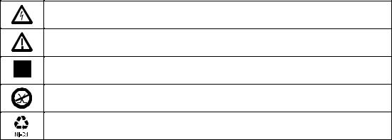
Table 2-1. International Electrical Symbols
Warning: Risk of electric shock.
Warning or Caution: Risk of damage or destruction to equipment or software. See explanations in the manual.
Equipment is protected by double insulation or reinforced insulation to protect the user against electric shock.
Do not connect this terminal to public communications networks, such as telephone systems.
Battery should be recycled. Refer to "Replacing the NiCad Battery Pack" in Chapter 8.
2-1

DSP-100/2000
Users Manual
XWarning
To avoid possible fire or electric shock when charging the battery or powering the test tool with ac power, use only the ac adapter/charger provided with the test tool.
WCaution
Never connect the test tool to telephone lines of any type, including ISDN lines. Doing so can damage the test tool.
∙Always turn on the test tool before connecting it to a cable. Turning the test tool on activates the tool’s input protection circuitry.
∙Except when monitoring network activity, never connect the test tool to an active network. Doing so may disrupt network operation.
∙When using a coaxial T-connector to connect the test tool to a network, never allow the T-connector to touch a conductive surface. Such contact may disrupt network operation.
∙Never attempt to insert any connector other than an RJ45 connector into the RJ45 jack. Inserting other connectors, such as RJ11 (telephone) connectors, can permanently damage the jack.
∙Never attempt to send data from a PC to the test tool while running a cable test. Doing so may cause erroneous test results.
∙Never operate portable transmitting devices during a cable test. Doing so may cause erroneous test results.
∙Never run tests with cables connected to both test connectors. Doing so may cause erroneous test results.
∙To ensure maximum accuracy of test results, perform the self-calibration procedure as described in “Calibrating the Test Tool” in Chapter 6.
2-2

Getting Started 2
Quick Start
Quick Start
This section is for users who want to start using the test tool immediately with minimal instruction. For suggestions on additional reading that may be helpful to you, see “Using this Manual” in Chapter 1.
Powering the Test Tool
Before powering the test tool or smart remote with the NiCad battery pack, charge the battery for about 3 hours. To charge the battery, connect the ac adapter/charger to the test tool or smart remote and to ac line power. You can operate the unit on ac power while the battery charges. A fully-charged battery typically lasts 10-12 hours. See “Battery Status” on page 2-31 for information on battery status messages.
Note
The ac adapter/charger will not power the test tool when the battery pack is removed.
The standard remote unit is powered by a 9V alkaline battery. The test tool monitors the remote unit and alerts you when the battery voltage is low.
Using the Menus
The test tool’s setup configuration, test selections, and test results are presented in a menu system. Table 2-2 shows the keys used to select items and move between screens in the menu system.
Key
U D L R
E
T
e
!@
#$
Table 2-2. Key Functions for the Menu System
Function
Allow up, down, left, and right movement on the display.
Selects the highlighted item.
Starts the highlighted test.
Exits the current screen.
Softkeys select the function displayed on the screen area above the key. Softkey functions depend on the screen displayed.
2-3

DSP-100/2000
Users Manual
Quick Configuration
The settings listed in Table 2-3 affect either the display format or the accuracy of your test results. Following the table are instructions for changing the settings. For a complete list of the test tool’s adjustable settings, refer to the later section “Setup.”
SETUP Setting
Test Standard and
Cable Type
Average Cable
Temperature
Conduit Setting
Remote End
Testing
Length Units
Numeric Format
Display and Report
Language
Power Line Noise
Filter Frequency
Table 2-3. Quick Configuration Settings
Description
Select the test standard and cable type you are using. Your selection determines which test specifications are used and which tests are run during cable testing. Fiber optic cable testing requires a Fluke DSP Fiber Optic Meter.
Select the cable temperature range that includes the average temperature where the cable is installed. Cable temperature is not applicable to all test standards.
The conduit setting is not applicable to all test standards.
Enables execution of the REMOTE tests. Select Disable or Auto Detect when using a standard remote.
Select meters or feet as the unit for length measurements.
Select a format (0.00 or 0,00) for display of decimal fractions.
Select English, German, French, Spanish, or Italian.
Select the frequency of the ac power in your area. The test tool filters out 50 or 60 Hz noise from measurements.
2-4
Getting Started 2
Quick Configuration
To change any of the settings shown in Table 2-3, proceed as follows:
1.Turn the rotary switch to SETUP.
2.If the setting you want to change is not on the first Setup screen, press $Page Down to see additional Setup screens.
3.Use DUto highlight the setting you want to change.
4.Press ! Choice.
5.Use DUto highlight the setting you want.
6.Press Eto store the highlighted setting.
7.Repeat steps 2 through 6 to change additional settings.
2-5

DSP-100/2000
Users Manual
Results within Accuracy Range
An asterisk following a test result value indicates that the value is within the test tool’s range of accuracy, as shown in Figure 2-1. All tests except the wire map test may produce results with an asterisk when the asterisk is required by the selected test standard.
The asterisk appears on displayed and printed test results, but does not appear in comma separated variable (CSV) data uploaded to a PC.
Pass |
|
* Pass Region |
Accuracy |
|
|
Limit |
Range of |
* Fail Region |
Test Tool |
|
|
Fail |
|
|
gc02f.eps |
Figure 2-1. The Asterisk and Test Tool Accuracy
2-6

Getting Started 2
Autotest on Twisted Pair Cable
Autotest on Twisted Pair Cable
Autotest performs all of the tests necessary to determine if the cable you are testing meets the test standards specified for your LAN installation.
The following tests apply to twisted pair cable:
∙Wire Map
∙Resistance
∙Length
∙Propagation Delay
∙Delay Skew
∙Impedance
∙NEXT (Near-end Crosstalk)
∙Attenuation
∙ACR (Attenuation to Crosstalk Ratio)
∙RL (Return Loss)
∙PSNEXT (Power Sum NEXT; Model DSP-2000 only)
Some test standards require a NEXT measurement from both ends of the cable. If you are using another main unit (Model DSP-100 only) or a smart remote as the remote unit, and you enable remote end testing on the main unit, the Autotest runs the REMOTE tests supported by the test tool if those tests apply to the selected test standard.
To Autotest twisted pair cable, refer to Figure 2-2 on the next page and proceed as follows:
Note
Standard remote units do not support remote end testing.
Note
If the calibration message appears after you start the Autotest, refer to “Calibrating the Test Tool” in Chapter 6 for complete calibration instructions.
2-7
DSP-100/2000
Users Manual
Horizontal
Cross Connect Blocks
2 Meters
 DSP-2000 CABLE ANALYZER
|
RJ45 |
|
Jacks |
Test Tool |
Transition |
|
Connector |
1 2 3 4
TEST |
SAVE |
FAULT |
|
INFO |
|
EXIT |
ENTER |
|
WAKE UP |
|
MONITOR |
SINGLE |
SETUP |
TEST |
|
AUTO |
|
TEST |
|
Wall
Outlet
OFF |
SPECIAL |
FUNCTIONS |
SMART
REMOTE
2 Meters 
Smart
Remote
 DSP-2000SR SMART REMOTE
PASS
TESTING
FAIL
LOW BATTERY
ON
OFF
gc03f.eps
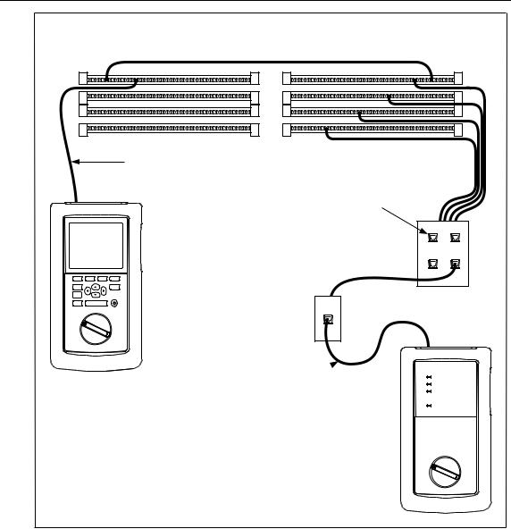
Figure 2-2. Autotest Connections for Twisted Pair Cable (Channel Configuration and Model DSP-2000 Shown)
2-8

Getting Started 2
Autotest on Twisted Pair Cable
1.If you are using a DSP-100 main unit as the remote, turn the remote unit’s rotary switch to SMART REMOTE. If you are using a smart remote unit, turn its rotary switch to ON.
2.Use a 2m patch cable of the correct impedance to connect the remote to the far end of the cable link.
3.On Model DSP-100, remove any cable connected to the test tool’s BNC connector.
4.Turn the rotary switch on the main unit to AUTOTEST.
5.Verify that the settings displayed are correct. You can change these settings in the SETUP mode.
6.Use a 2m patch cable of the correct impedance to connect the test tool to the near end of the cable link. On Model DSP-2000, connect to the CABLE TEST jack.
7.Press T to start the Autotest.
2-9

DSP-100/2000
Users Manual
Autotest on Coaxial Cable
The following tests are run during an Autotest on coaxial cable:
∙Impedance
∙Resistance
∙Length
∙Anomaly detection (Results shown only if anomalies are detected.)
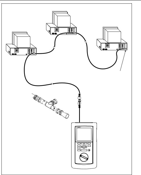
To run an Autotest on coaxial cable, refer to Figure 2-3 and proceed as follows:
1.Turn off any PC nodes connected to the cable you are testing.
2.If you want the Autotest to report cable length, remove the terminator from the far end of the cable.
3.Turn the rotary switch to AUTOTEST.
4.Verify that the test standard and cable type displayed are correct. You can change these settings in the SETUP mode.
5.Remove any cable connected to the test tool’s unused RJ45 connector.
6.Remove the terminator from the near end of the coaxial cable and connect the cable to the BNC connector on the test tool. On Model DSP-2000, use the RJ45 to BNC adapter to connect the cable to the CABLE TEST jack.
7.Press T to start the Autotest.
2-10
Getting Started 2
Autotest on Coaxial Cable
|
|
|
|
|
|
|
PC |
|
|
|
|
|
|
|
|
|
|
|
|
|
|
|
|
|
|
|
|
|
|
|
|
|
|
|
|
|
|
|
|
|
|
PC |
|
|
|
|
|
|
|
PC |
|
|
|
|
|
|
8 |
7 |
6 |
5 |
4 |
3 |
2 |
1 |
|
|
|
|
|
|
|
|
|
|
|
|
|
|
|
|
|
|
|
|
|
|
|
|
|
|
|
|
|
|
|
|
|
|
|
|
|
|
|
|
|
|
|
|
|
|
|
|
|
|
|
|
8 |
7 |
6 |
5 |
4 |
3 |
2 |
1 |
8 |
7 |
6 |
5 |
4 |
3 |
2 |
1 |
|
|
|
|
|
|
|
|
|
|
|
|
|
|
|
|
|
|
|
|
|
|
|
|
|
|
|
|
|
|
|
|
|
|
For Length Test, |
|||||||
|
|
|
|
|
|
|
|
|
|
|
|
|
|
|
|
|
remove far-end |
|||||||
|
|
|
|
|
|
|
|
|
|
|
|
|
|
|
|
|
Terminator |
|
|
|
|
|
||
|
|
|
|
|
|
|
BNC “T” |
|
|
|
|
|
|
|
|
|
|
|
|
|
|
|
|
|
|
|
|
|
|
|
|
Connector |
|
|
|
|
|
|
|
|
|
|
|
|
|
|
|
|
|
|
|
|
|
|
|
|
|
|
|
|
|
|
|
|
DSP-2000 CABLE ANALYZER |
|
|
|
|
|
|
|
||
|
|
|
|
|
|
|
|
|
|
|
|
|
|
1 |
2 |
3 |
4 |
|
|
|
|
|
|
|
|
|
|
|
|
|
|
|
|
|
|
|
|
|
TEST |
|
|
SAVE |
|
|
|
|
|
|
|
|
|
|
|
|
|
|
|
|
|
|
|
|
|
FAULT |
|
|
|
|
|
|
|
|
|
|
|
|
|
|
|
|
|
|
|
|
|
|
|
|
INFO |
|
|
|
|
|
|
|
|
|
|
|
|
|
|
|
|
|
|
|
|
|
|
|
|
EXIT |
|
ENTER |
|
|
|
|
|
|
|
|
|
|
|
|
|
|
|
|
|
|
|
|
|
|
|
|
MONITOR |
|
|
|
|
|
|
|
|
|
|
|
|
|
|
|
|
|
|
|
|
|
|
SINGLE |
|
SETUP |
|
|
|
|
|
|
|
|
|
|
|
|
|
|
|
Test Tool |
|
|
|
|
|
TEST |
|
|
|
|
|
|
|
|
|
||
|
|
|
|
|
|
|
|
|
|
|
|
AUTO |
|
|
|
|
|
|
|
|
|
|||
|
|
|
|
|
|
|
|
|
|
|
|
TEST |
|
|
|
|
|
|
|
|
|
|
||
|
|
|
|
|
|
|
|
|
|
|
|
|
|
|
|
|
|
|
|
|
|
|
||
|
|
|
|
|
|
|
|
|
|
|
|
|
|
OFF |
|
|
SPECIAL |
|
|
|
|
|
|
|
|
|
|
|
|
|
|
|
|
|
|
|
|
|
|
|
FUNCTIONS |
|
|
|
|
|
|
|
|
|
|
|
|
|
|
|
|
|
|
|
|
|
|
|
|
|
SMART |
|
|
|
|
|
|
|
|
|
|
|
|
|
|
|
|
|
|
|
|
|
|
|
|
REMOTE |
|
|
|
|
|
|
|
|
|
|
|
|
|
|
|
|
|
|
|
|
|
|
|
|
|
|
|
|
|
|
|
gc04f.epc |
Figure 2-3. Autotest Connections for Coaxial Cable (Model DSP-2000 Shown)
2-11
DSP-100/2000
Users Manual
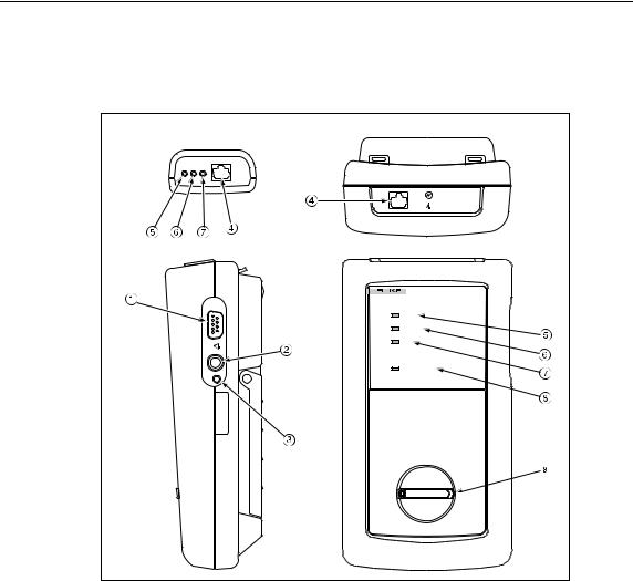
Main Unit Features
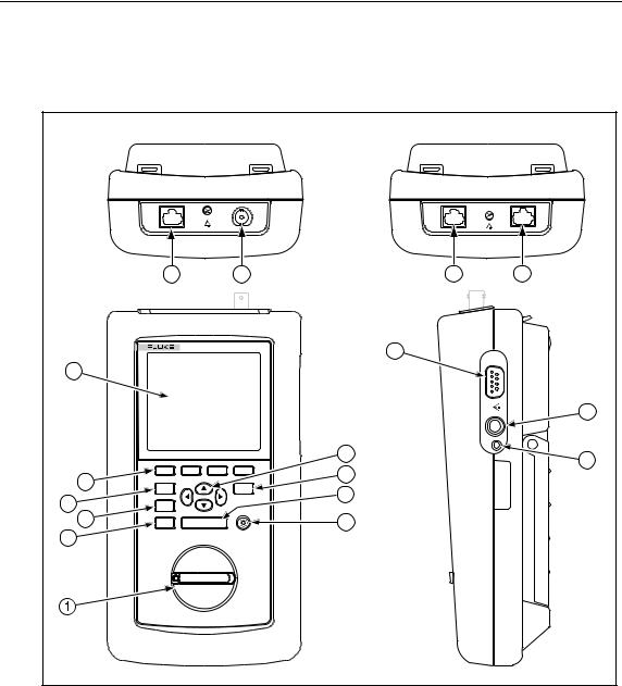
Figure 2-4 shows the features on the main unit and Table 2-4 explains their functions. Features shown in light gray are found on Model DSP-100 only.
|
|
DSP-100 |
|
DSP-2000 |
|
||
|
|
|
|
|
CABLE |
MONITOR |
|
|
|
|
|
|
TEST |
|
|
|
14 |
|
|
15 |
|
14 |
14 |
|
|
DSP-2000 CABLE ANALYZER |
11 |
|
|
||
|
|
|
|
|
|
|
|
6 |
|
|
|
|
|
|
|
|
|
|
|
|
|
|
12 |
|
|
|
|
|
7 |
|
13 |
|
|
|
|
|
8 |
|
|
|
1 |
2 |
3 |
4 |
|
|
|
5 |
|
|
|
|
|
|
|
TEST |
|
|
SAVE |
9 |
|
|
|
|
|
|
|
|
|||
4 |
FAULT |
|
|
|
|
|
|
|
|
|
|
|
|
||
INFO |
|
|
|
|
|
|
|
3 |
EXIT |
|
ENTER |
|
10 |
|
|
2 |
|
|
MONITOR |
WAKE UP |
|
|
|
|
|
|
|
|
|
||
SINGLE |
|
SETUP |
|
|
|
||
|
TEST |
|
|
|
|
|
|
|
AUTO |
|
|
|
|
|
|
|
TEST |
|
|
|
|
|
|
|
OFF |
|
|
SPECIAL |
|
|
|
|
|
|
FUNCTIONS |
|
|
|
|
|
|
|
|
|
|
|
|
|
|
|
|
SMART |
|
|
|
|
|
|
|
REMOTE |
|
|
|
|
|
|
|
|
|
|
gc05f.eps |
Figure 2-4. Main Unit Features
2-12

Getting Started 2
Main Unit Features
Item
1
2
3
4
5
6
7
8
9
0
f
g
h
i
j
Feature
Rotary Switch
e
F
T
! @
#$
Display
L R U D
S
E
C
WAKE UP
RS-232C serial port
AC adapter/ charger jack
AC power indicator
RJ45
connector(s)
BNC connector
Table 2-4. Main Unit Features
Description
Selects the test tool’s modes.
Exits the current screen.
Model DSP-2000 only. Automatically provides more specific information on the cause of an Autotest failure.
Starts the highlighted test or restarts the test last run.
Provide functions related to the concurrent display. Softkey functions are shown in the display area above the keys.
A LCD display with backlight and adjustable contrast.
Allow left, right, up, and down movement on the display. Increase or decrease the numerical values of user-definable parameters.
Saves Autotest results and parameter changes in memory.
Selects the highlighted item from a menu.
Controls the display backlight. Pressing for 1 second allows adjustment of the display contrast. Reactivates the test tool when the tool is in power down mode.
A 9-pin connector for interfacing with a printer or host computer via a standard IBM-AT EIA RS-232C serial cable.
Connection for the ac adapter/charger supplied with the test tool.
LED Style 1: A green LED that turns on when the test tool is powered with the ac adapter/charger.
LED Style 2: A multicolor LED with four states:
Off: AC adapter/charger is not connected, or is connected without the battery pack installed.
Blinking Red: The ac adapter/charger is trickle charging the battery in preparation for fast charging. This mode indicates an extremely low battery voltage. The test tool may not operate.
Steady Red: The ac adapter/charger is fast charging the battery.
Steady Green: Fast charging is complete. The ac adapter/charger continues to trickle charge the battery.
A shielded 8-pin jack for shielded and unshielded twisted pair cable. On Model DSP-2000, this jack is labeled CABLE TEST. Model DSP-2000 has an additional RJ45 jack labeled MONITOR, which is used for 10/100BaseTX traffic and hub tests.
Model DSP-100 only. A connector for coaxial cable.
2-13
DSP-100/2000
Users Manual
Remote Features
Figure 2-5 shows the features on the standard and smart remote units. Table 2-5 explains the functions of these items.
Smart Remote |
Standard Remote |
PASS TEST FAIL |
DSP-2000SR SMART REMOTE |
PASS |
TESTING |
FAIL |
LOW BATTERY |
ON |
OFF |
gc06f.eps
Figure 2-5. Standard and Smart Remote Features
2-14
Loading...