


 Loading...
®
Model 187 & 189
True RMS Multimeter
Users Manual
August 2000, Rev.2, 6/02
© 2000, 2002 Fluke Corporation. All rights reserved. Printed in U.S.A. All product names are trademarks of their respective companies.

Lifetime Limited Warranty
Each Fluke 20, 70, 80, 170 and 180 Series DMM will be free from defects in material and workmanship for its lifetime. As used herein, “lifetime” is defined as seven years after Fluke discontinues manufacturing the product, but the warranty period shall be at least ten years from the date of purchase. This warranty does not cover fuses, disposable batteries, damage from neglect, misuse, contamination, alteration, accident or abnormal conditions of operation or handling, including failures caused by use outside of the product’s specifications, or normal wear and tear of mechanical components. This warranty covers the original purchaser only and is not transferable.
For ten years from the date of purchase, this warranty also covers the LCD. Thereafter, for the lifetime of the DMM, Fluke will replace the LCD for a fee based on then current component acquisition costs.
To establish original ownership and prove date of purchase, please complete and return the registration card accompanying the product, or register your product on http://www.fluke.com. Fluke will, at its option, repair at no charge, replace or refund the purchase price of a defec-
tive product purchased through a Fluke authorized sales outlet and at the applicable international price. Fluke reserves the right to charge for importation costs of repair/replacement parts if the product purchased in one country is sent for repair elsewhere.
If the product is defective, contact your nearest Fluke authorized service center to obtain return authorization information, then send the product to that service center, with a description of the difficulty, postage and insurance prepaid (FOB Destination). Fluke assumes no risk for damage in transit. Fluke will pay return transportation for product repaired or replaced in-warranty. Before making any non-warranty repair, Fluke will estimate cost and obtain authorization, then invoice you for repair and return transportation.
THIS WARRANTY IS YOUR ONLY REMEDY. NO OTHER WARRANTIES, SUCH AS FITNESS FOR A PARTICULAR PURPOSE, ARE EXPRESSED OR IMPLIED. FLUKE SHALL NOT BE LIABLE FOR ANY SPECIAL, INDIRECT, INCIDENTAL OR CONSEQUENTIAL DAMAGES OR LOSSES, INCLUDING LOSS OF DATA, ARISING FROM ANY CAUSE OR THEORY. AUTHORIZED RESELLERS ARE NOT AUTHORIZED TO EXTEND ANY DIFFERENT WARRANTY ON FLUKE’S BEHALF. Since some states do not allow the exclusion or limitation of an implied warranty or of incidental or consequential damages, this limitation of liability may not apply to you. If any provision of this warranty is held invalid or unenforceable by a court or other decision-maker of competent jurisdiction, such holding will not affect the validity or enforceability of any other provision.
Fluke Corporation |
Fluke Europe B.V. |
P.O. Box 9090 |
P.O. Box 1186 |
Everett, WA 98206-9090 |
5602 BD Eindhoven |
U.S.A. |
The Netherlands |
2/02
Table of Contents
Chapter |
Title |
Page |
1 |
Before You Start .......................................................................................................... |
1-1 |
|
Safety Information.......................................................................................................... |
1-1 |
|
Contacting Fluke............................................................................................................ |
1-1 |
|
Symbols ......................................................................................................................... |
1-4 |
2 |
Getting Acquainted...................................................................................................... |
2-1 |
|
Introduction.................................................................................................................... |
2-1 |
|
Turning the Meter On..................................................................................................... |
2-1 |
|
Battery Considerations .................................................................................................. |
2-2 |
|
Automatic Power Off ................................................................................................. |
2-2 |
|
Automatic Backlight Off............................................................................................. |
2-3 |
|
Low Battery Indication............................................................................................... |
2-3 |
|
Rotary Switch................................................................................................................. |
2-4 |
|
Pushbuttons................................................................................................................... |
2-5 |
i

Model 187 & 189
Users Manual
|
Selecting the Range....................................................................................................... |
2-10 |
|
Understanding the Display ............................................................................................. |
2-10 |
|
Primary Display ......................................................................................................... |
2-10 |
|
Secondary Display..................................................................................................... |
2-11 |
|
Bar Graph.................................................................................................................. |
2-11 |
|
Using the Input Terminals .............................................................................................. |
2-17 |
|
Using Display Hold ......................................................................................................... |
2-18 |
|
Using AutoHOLD............................................................................................................ |
2-19 |
|
Using MIN MAX.............................................................................................................. |
2-19 |
|
Using FAST MN MX ....................................................................................................... |
2-21 |
|
Using HOLD with MIN MAX or FAST MN MX............................................................ |
2-22 |
|
Using Relative Mode (REL)............................................................................................ |
2-22 |
3 |
Making Measurements................................................................................................. |
3-1 |
|
Introduction .................................................................................................................... |
3-1 |
|
Measuring Voltage ......................................................................................................... |
3-1 |
|
Measuring AC Voltage............................................................................................... |
3-2 |
|
dB Measurements in AC Volts Functions .................................................................. |
3-3 |
|
Measuring DC Voltage .............................................................................................. |
3-4 |
|
Both AC and DC Voltage Measurements .................................................................. |
3-4 |
|
Measuring Resistance.................................................................................................... |
3-6 |
|
Testing for Continuity ..................................................................................................... |
3-8 |
|
Using Conductance for High Resistance Tests .............................................................. |
3-9 |
|
Measuring Capacitance.................................................................................................. |
3-12 |
|
Testing Diodes ............................................................................................................... |
3-13 |
|
Measuring Temperature ................................................................................................. |
3-15 |
|
Measuring Current ......................................................................................................... |
3-16 |
|
Input Alert™ Feature ................................................................................................. |
3-17 |
ii
|
|
Contents (continued) |
|
Measuring AC Current .............................................................................................. |
3-18 |
|
Measuring DC Current .............................................................................................. |
3-20 |
|
Measuring Frequency .................................................................................................... |
3-22 |
|
Measuring Duty Cycle.................................................................................................... |
3-23 |
|
Measuring Pulse Width.................................................................................................. |
3-25 |
4 |
Using Memory & Communications Features ............................................................ |
4-1 |
|
Introduction.................................................................................................................... |
4-1 |
|
Types of Memory ........................................................................................................... |
4-1 |
|
Saved Readings Memory.......................................................................................... |
4-1 |
|
Logged Readings Memory........................................................................................ |
4-1 |
|
Storing Saved Readings ................................................................................................ |
4-2 |
|
Starting Logging ............................................................................................................ |
4-2 |
|
Stopping Logging........................................................................................................... |
4-2 |
|
Viewing Memory Data.................................................................................................... |
4-3 |
|
Clearing Memory ........................................................................................................... |
4-5 |
|
Using Communications (187 and 189) .......................................................................... |
4-5 |
5 |
Changing the Default Settings ................................................................................... |
5-1 |
|
Introduction.................................................................................................................... |
5-1 |
|
Selecting Setup Options ................................................................................................ |
5-1 |
|
Adjusting the Temperature Offset.................................................................................. |
5-4 |
|
Selecting Display Resolution (3 1/2 or 4 1/2 Digits)...................................................... |
5-6 |
|
Setting the Power Off Timeout....................................................................................... |
5-6 |
|
Setting the 24-Hour Clock.............................................................................................. |
5-7 |
|
Setting the Line (Main) Frequency................................................................................. |
5-7 |
|
Returning to Factory Defaults ........................................................................................ |
5-8 |
|
Saving Setup Options .................................................................................................... |
5-8 |
iii

Model 187 & 189
Users Manual
6 |
Maintenance ................................................................................................................. |
6-1 |
|
Introduction .................................................................................................................... |
6-1 |
|
General Maintenance..................................................................................................... |
6-1 |
|
Testing the Fuses........................................................................................................... |
6-1 |
|
Replacing the Batteries .................................................................................................. |
6-3 |
|
Replacing the Fuses ...................................................................................................... |
6-5 |
|
User-Replaceable Parts ................................................................................................. |
6-5 |
|
In Case of Difficulty ........................................................................................................ |
6-5 |
7 |
Specifications............................................................................................................... |
7-1 |
|
Safety and Compliances ................................................................................................ |
7-1 |
|
Physical Specifications................................................................................................... |
7-2 |
|
Feature Summary........................................................................................................... |
7-3 |
|
Basic Specifications ....................................................................................................... |
7-4 |
|
Detailed Accuracy Specifications ................................................................................... |
7-5 |
|
Frequency Counter Sensitivity ....................................................................................... |
7-11 |
|
Burden Voltage (A, mA, µA)........................................................................................... |
7-11 |
|
Input Characteristics....................................................................................................... |
7-12 |
iv
List of Tables
Table |
|
Title |
Page |
1-1. |
Safety Information................................................................................................................. |
|
1-2 |
1-2. |
International Electrical Symbols............................................................................................ |
|
1-4 |
2-1. |
Rotary Switch Selections ...................................................................................................... |
|
2-6 |
2-2. |
Pushbuttons.......................................................................................................................... |
|
2-8 |
2-3. |
Display Features................................................................................................................... |
|
2-13 |
3-1. |
Current Measurement ........................................................................................................... |
|
3-16 |
4-1. |
View Display ......................................................................................................................... |
|
4-4 |
5-1. Function Specific Setup Selections....................................................................................... |
|
5-2 |
|
5-2. |
Common Setup Selections ................................................................................................... |
|
5-3 |
6-1. |
User-Replaceable Parts........................................................................................................ |
|
6-6 |
v

Model 187 & 189
Users Manual
vi
List of Figures
Figure |
|
Title |
Page |
2-1. |
AC Volts Display ................................................................................................................... |
|
2-2 |
2-2. |
Rotary Switch........................................................................................................................ |
|
2-4 |
2-3. |
Pushbuttons.......................................................................................................................... |
|
2-5 |
2-4. |
Display Features................................................................................................................... |
|
2-12 |
2-5. |
Input Terminals ..................................................................................................................... |
|
2-17 |
2-6. Display Hold and AutoHOLD ................................................................................................ |
|
2-18 |
|
2-7. |
Min Max Avg ......................................................................................................................... |
|
2-21 |
2-8. |
Relative Mode....................................................................................................................... |
|
2-22 |
3-1. |
AC Voltage Measurement..................................................................................................... |
|
3-2 |
3-2. |
dBm Display.......................................................................................................................... |
|
3-3 |
3-3. AC and DC Display ............................................................................................................... |
|
3-5 |
|
3-4. |
DC Voltage Measurement..................................................................................................... |
|
3-6 |
3-5. |
Resistance Measurement ..................................................................................................... |
|
3-7 |
3-6. |
Continuity Test...................................................................................................................... |
|
3-10 |
3-7. |
Conductance Measurement.................................................................................................. |
|
3-11 |
3-8. |
Capacitance Measurement ................................................................................................... |
|
3-13 |
3-9. |
Diode Test ............................................................................................................................ |
|
3-14 |
vii

Model 187 & 189
Users Manual
3-10. |
Temperature Measurement................................................................................................... |
3-15 |
3-11. |
AC Current Measurement...................................................................................................... |
3-19 |
3-12. |
DC Current Measurement ..................................................................................................... |
3-21 |
3-13. |
Functions Allowing Frequency Measurement........................................................................ |
3-22 |
3-14. |
Hz Display ............................................................................................................................. |
3-23 |
3-15. |
Duty Cycle Measurements .................................................................................................... |
3-24 |
3-16. |
Duty Cycle Display ................................................................................................................ |
3-25 |
3-17. |
Pulse Width Measurements................................................................................................... |
3-26 |
3-18. |
Pulse Width Display .............................................................................................................. |
3-27 |
4-1. |
View Display.......................................................................................................................... |
4-4 |
5-1. |
Adjusting Temperature Offset ............................................................................................... |
5-5 |
6-1. |
Testing the Current Fuses..................................................................................................... |
6-2 |
6-2. |
Battery and Fuse Replacement ............................................................................................. |
6-4 |
viii
Safety Information
The Fluke Model 187 and Model 189 True RMS Multimeters (hereafter referred to as the “meter”) comply with:
•EN61010.1:1993
•ANSI/ISA S82.01-1994
•CAN/CSA C22.2 No. 1010.1-92
•1000V Overvoltage Category III, Pollution Degree 2
•600V Overvoltage Category IV, Pollution Degree 2
•UL 3111-1
Use the meter only as specified in this manual. Otherwise, the protection provided by the meter may be impaired. Refer to safety information in Table 1-1.
A Warning identifies conditions and actions that pose hazards to the user. A Caution identifies conditions and actions that may damage the meter or the equipment under test.
Chapter 1
Before You Start
Contacting Fluke
To order accessories, receive assistance, or locate the nearest Fluke distributor or Service Center, call:
USA: 1-888-99-FLUKE (1-888-993-5853) Canada: 1-800-36-FLUKE (1-800-363-5853) Europe: +31 402-678-200
Japan: +81-3-3434-0181
Singapore: +65-738-5655
Anywhere in the world: +1-425-446-5500
Address correspondence to: |
|
Fluke Corporation |
Fluke Europe B.V. |
P.O. Box 9090, |
P.O. Box 1186, |
Everett, WA 98206-9090 |
5602 BD Eindhoven |
USA |
The Netherlands |
Visit us on the World Wide Web at: www.fluke.com
1-1

Model 187 & 189
Users Manual
Table 1-1. Safety Information
WWarning
To avoid possible electric shock or personal injury, follow these guidelines:
•Do not use the meter if it is damaged. Before you use the meter, inspect the case. Look for cracks or missing plastic. Pay particular attention to the insulation surrounding the connectors.
•Inspect the test leads for damaged insulation or exposed metal. Check the test leads for continuity. Replace damaged test leads before you use the meter.
•If this product is used in a manner not specified by the manufacturer, the protection provided by the equipment may be impaired.
•Do not use the meter if it operates abnormally. Protection may be impaired. When in doubt, have the meter serviced.
•Do not operate the meter around explosive gas, vapor, or dust.
•Do not apply more than the rated voltage, as marked on the meter, between terminals or between any terminal and earth ground.
•Before use, verify the meter’s operation by measuring a known voltage.
•When measuring current, turn off circuit power before connecting the meter in the circuit. Remember to place the meter in series with the circuit.
•When servicing the meter, use only specified replacement parts.
•Use caution when working above 30 V ac rms, 42 V peak, or 60 V dc. Such voltages pose a shock hazard.
•Avoid working alone.
1-2

Before You Start |
1 |
Safety Information |
Table 1-1. Safety Information (cont.)
WWarning
•When using the probes, keep your fingers behind the finger guards on the probes.
•Connect the common test lead before you connect the live test lead. When you disconnect test leads, disconnect the live test lead first.
•Remove test leads from the meter before you open the battery door.
•Do not operate the meter with the battery door or portions of the cover removed or loosened.
•To avoid false readings, which could lead to possible electric shock or personal injury, replace the batteries as soon as the low battery indicator (M) appears.
•Use only type AA batteries, properly installed in the meter case, to power the meter.
•To avoid the potential for fire or electrical shock, do not connect the thermocouples to electrically live circuits.
Caution
To avoid possible damage to the meter or to the equipment under test, follow these guidelines:
•Disconnect circuit power and discharge all high-voltage capacitors before testing resistance, continuity, diodes, or capacitance.
•Use the proper terminals, function, and range for your measurements.
•Before measuring current, check the meter’s fuses and turn power OFF to the circuit before connecting the meter to the circuit.
1-3
Model 187 & 189
Users Manual
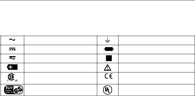
Symbols
Symbols used on the meter and in this manual are explained in Table 1-2.
Table 1-2. International Electrical Symbols
AC (Alternating Current)
DC (Direct Current)
AC and DC
Battery
Complies with relevant Canadian Standards Association directives
Inspected and licensed by TÜ V Product Services.
Earth ground
Fuse
Double insulated
Important information
Complies with European Union directives
Underwriters Laboratories, Inc.
1-4
Introduction
Although this manual describes the operation of both Models 187 and 189, all illustrations and examples assume use of Model 189. Additional capabilities with Model 189 are discussed in Chapter 4. These capabilities include the following:
•An enhanced memory function that features an additional position (VIEW MEM) on the rotary switch.
•Logging
•Save
•Memory
Chapter 2
Getting Acquainted
Turning the Meter On
To turn the meter on, turn the rotary switch from OFF to any switch setting.
The ac volts function (shown in Figure 2-1) is assumed in the following discussion. You do not need connections to the input terminals at this time.
If you want a view of the full display (all segments illuminated), press and hold Q while turning the meter on. Release the button when you are done viewing the full display.
2-1

Model 187 & 189
Users Manual
tc031f.eps
Figure 2-1. AC Volts Display
Battery Considerations
The meter uses four AA alkaline batteries. The following paragraphs describe several techniques used to conserve battery power.
Automatic Power Off
The display blanks and the meter goes into a “sleep” mode if you have not changed the rotary switch position or pressed a button for a set period. While in Sleep mode, pressing any button turns the meter on. The meter then returns to the display for the function selected with the rotary switch; all previously activated button features (HOLD, Hz, etc.) are discarded.
The automatic power off is preset to 15 minutes. From the Setup menu (see Chapter 5), you can specify a maximum period of 23 hours, 59 minutes. If you set the period to 0, the meter remains on until you turn the rotary switch to OFF or the batteries become too weak.
Automatic power off does not occur if the meter is in MIN MAX, FAST MN MX, AutoHOLD, or LOGGING
(Model 189) mode.
2-2

Getting Acquainted |
2 |
Battery Considerations |
Automatic Backlight Off
Press T to select the backlight level (low, high, or off.) In low or high, the backlight turns off automatically after a given period. This period is also preset to 15 minutes and can be set to a maximum of 99 minutes from the setup menu. If the period is set to 0, the backlight is on indefinitely and can only be turned off by pressing T or turning the meter off.
Note
See Chapter 5 for power off and backlight off setup information.
Low Battery Indication
A constant battery icon ( B) in the upper left corner of the display notifies you that the batteries are low and should be replaced.
WWarning
To avoid false readings, which could lead to possible electric shock or personal injury, replace the batteries as soon as the battery icon ( B) appears.
A flashing battery icon means that battery failure is imminent. The backlight cannot be used in this condition. MIN MAX and FAST MN MX features turn off. For Model 189, logging and communications also cease.
2-3
Model 187 & 189
Users Manual
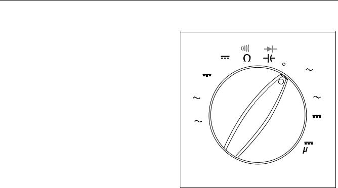
Rotary Switch
Turn the meter on by selecting any measurement function (identified with white letters around the rotary switch). The meter presents a standard display for that function (range, measurement units, modifiers, etc.) The display may also be influenced by some of the choices made in Setup.
Use the blue button to select any rotary switch alternate function (labeled in blue letters). You can also use other buttons to choose modifiers for the selected function.
When you turn the rotary switch from one function to another, a display for the new function appears. Button choices made in one function do not carry over into another function.
With Model 189, a VIEW MEM switch position is available; refer to Chapter 4 for more information.
The rotary switch is shown in Figure 2-2. Each position is described in Table 2-1.
nS
mV
ac+dc
V
ac+dc
mV
dB
V
dB
OFF
 F
F
C
A mA
 A
A
A mA
ac+dc
A
ac+dc
VIEW MEM
CLEAR MEM
tc012f.eps
Figure 2-2. Rotary Switch
2-4
Getting Acquainted
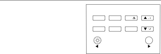
Pushbuttons 2
Pushbuttons
The buttons activate features that augment the function selected with the rotary switch. The buttons are shown in Figure 2-3 and described in Table 2-2.
Use the blue button ( %) to access functions labeled in blue for some of the rotary switch positions. Table 2-1 defines all blue button functions.
AutoHOLD |
FAST MN MX |
LOGGING |
YES |
HOLD |
MIN MAX |
REL |
|
|
CANCEL |
SAVE |
NO |
|
Hz % ms |
RANGE |
|
SETUP |
|
|
|
Use the yellow button ( O) followed by other buttons to access additional features. These features appear in yellow above the appropriate keys. Table 2-2 defines yellow button features. This manual identifies the yellow button feature in parentheses following the button sequence . For example, activating the FAST MN MX mode appears as O M (FAST MN MX).
tc013f.eps
Figure 2-3. Pushbuttons
The following yellow button features are not available on Model 187: (YES), (NO), (LOGGING), and (SAVE).
2-5

Model 187 & 189
Users Manual
|
Table 2-1. Rotary Switch Selections |
|
|
|
|
Position |
Rotary Switch Function |
% Blue Key Function |
\ |
AC voltage measurement from 0 V to 1000.0 V |
dB over AC, AC over dB |
, |
AC millivolt measurement from 0 mV to 3000.0 mV |
dB over AC, AC over dB |
$ |
DC voltage measurement from 0 V to 1000.0 V |
AC over DC (AC in primary display, DC in secondary |
|
||
|
|
display), DC over AC, ac+dc |
|
|
|
m |
DC millivolt measurement from 0 mV to 3000.0 mV |
AC over DC (AC in primary display, DC in secondary |
|
||
|
|
display), DC over AC, ac+dc |
|
|
|
j |
Resistance measurement from 0 Ω to 500.0 MΩ |
Continuity test |
|
Conductance measurement from 0 nS to 50.00 nS |
|
|
|
|
z |
Capacitance measurement from 0.001 nF to 50 mF |
Diode test |
w |
Temperature measurement |
Toggles between ° C and ° F. |
2-6
Getting Acquainted
Pushbuttons 2
Table 2-1. Rotary Switch Positions (cont.)
Position
I
=
K
x
VIEW
MEM
Rotary Switch Function
AC current measurements from 0 mA to 20.000 A
AC current measurements from 0 A to 5000.0 A
DC current measurements from 0 mA to 20.000 A
DC current measurements from 0 A to 5000.0 A
(Model 189 only.) Access data held in the meter’s memory. See Chapter 4 for more information.
% Blue Key Function
none
none
AC over DC (AC in primary display, DC in secondary display), DC over AC, ac+dc
AC over DC (AC in primary display, DC in secondary display), DC over AC, ac+dc
CLEAR MEM. See Chapter 4 for more information.
2-7

Model 187 & 189
Users Manual
|
|
Table 2-2. Pushbuttons |
|
|
|
|
|
|
|
|
|
|
Yellow Button |
|
Button |
Description |
|
Function |
Description |
|
|
|
|
|
Note
Press O to access “Yellow Button Functions.” The O box and the 24-hour clock appear in the lower corners of the display and the primary display freezes, allowing time to press a second button.
T l
Q
M
D
Press to turn backlight on or off. Also, in Setup, use the arrow function (l) to select the previous digit or item in a list.
Press to freeze the displayed value. Press again to release the display.
Press to start retaining min, max, and average values. Press successively to display max, min, and average values. Press O N (CANCEL) to stop.
Press to store the present reading as an offset reference; subsequent readings show only the relative difference from this value. Press again to show the difference as a percentage of the reference.
SETUP
OT
AutoHOLD
O Q
FAST MN MX
O M
LOGGING
O D
Press to access Setup selections. Press to store a Setup selection and proceed to the next selection.
Press to begin AutoHOLD; the last stable reading is displayed.
Press to start FAST MN MX mode, where min and max values for short duration events are stored.
Press to start and stop Logging (Model 189). Press O + N (CANCEL) to stop.
2-8

Getting Acquainted
Pushbuttons 2
Table 2-2. Pushbuttons (cont.)
Button
[
]
R
N
%
s
Description
•In Setup, increment a digit .
•In counter functions, select positive pulse slope.
•In ohms continuity, select beep on open.
•In VIEW MEM, see Chapter 4 (Model 189).
•In Setup, decrement a digit .
•In counter functions, select negative pulse slope.
•In ohms continuity, select beep on short.
•In VIEW MEM, see Chapter 4 (Model 189).
Yellow Button |
|
Function |
Description |
(none)
(none)
Exit AUTO and enter MANUAL ranging. In MANUAL, |
SAVE |
Press to save present reading |
select next input range. Press O N |
O R |
(Model 189) |
(CANCEL) to return to AUTO. |
|
|
Successively press for frequency, duty cycle, and |
CANCEL |
CANCEL any % (blue key) function |
pulse width. |
O N |
and all other button features. |
The blue button. Press to access blue functions on |
(none) |
|
the rotary switch. In Setup, use arrow function ( s) to |
|
|
select the next digit or item in a list. |
|
|
2-9

Model 187 & 189
Users Manual
Selecting the Range
Press R to select either a fixed range or the autorange feature.
Note
You cannot use R in conductance, diode test, and temperature functions or with the REL, MIN MAX, and FAST MN MX features. These selections all use a specific fixed range.
Autoranging (AUTO lighted in the display) always comes on initially when you select a new function. In autorange, the meter selects the lowest input range possible, ensuring that the reading appears with the highest available precision (resolution).
If AUTO is already on, press R to enter MANUAL ranging in the present range. You can then select the next manual range each time you press R. Return to autoranging by pressing O N (CANCEL).
Understanding the Display
Display features are shown in Figure 2-4 and described in Table 2-3. Major display features are described in the following paragraphs.
Note
You can show all display segments (as shown in Figure 2-4) by pressing Q while turning the meter on. Release Q to turn off the full display.
Primary Display
The primary display usually shows the present reading for the rotary switch function. For most of these functions, the primary display can be set to show 4 or 5 digits. See Chapter 5 for more information about display digits.
Other uses for this display are:
•AutoHOLD: most recent held reading.
•MIN MAX: maximum, minimum, or average value.
2-10

Getting Acquainted |
2 |
Understanding the Display |
•dB (in ac volts functions): the dBm or dBV value.
•REL: the difference between the present reading and a stored reference reading.
•Setup: various messages (see Chapter 5).
•Overload conditions: OL displayed.
•Error conditions.
Bar Graph
The bar graph provides an analog indication of the measured input. For most measurement functions, the bar graph updates 40 times per second. Since this response is much faster than the digital display, the bar graph is useful for making peak and null adjustments and for observing rapidly changing inputs. The bar graph is not available in temperature, capacitance, ac over dc, dc over ac, and ac+dc functions.
Secondary Display
The secondary display often shows the present reading when the primary display shows some other feature (MIN MAX, REL ∆ , etc.)
When multiple features are active, the secondary display shows one of the values. For example, Hz could appear in the secondary display while dB appears in the primary display.
2-11

Model 187 & 189
Users Manual
8 |
10 |
12 |
7 |
9 |
11 |
6 |
|
|
5 |
|
13 |
|
|
|
4 |
|
|
3 |
|
|
2 |
|
|
1 |
|
14 |
|
|
|
17 |
16 |
15 |
tc011f.eps
Figure 2-4. Display Features
2-12

|
|
|
|
|
|
|
|
|
|
Getting Acquainted |
2 |
|
|
|
|
|
|
|
|
|
|
Understanding the Display |
|
|
|
|
|
|
|
|
|
|
|
Table 2-3. Display Features |
|
|
|
|
|
|
|
|
|
|
|
|
|
|
Number |
|
|
|
|
Feature |
|
|
Description |
|
|
|
|
~ |
|
|
|
|
|
Continuity test function is selected. |
|
||
|
|
|
|
|
|
|
|
|
|
Bar Graph. |
|
|
|
|
|
|
|
|
|
|
|
In normal operation 0 (zero) is on the left. In Relative %, 0 is in the center, negative |
|
|
|
|
|
|
|
|
|
|
|
|
|
|
|
|
|
|
|
|
|
|
|
values are to the left and positive to the right. |
|
|
|
|
|
|
|
|
|
|
|
The polarity indicator left of the bar graph shows the polarity of the input. Both polarity |
|
|
|
|
|
|
|
|
|
|
|
indicators appear in REL% mode. |
|
|
|
|
|
|
|
|
|
|
|
The arrow right of the bar graph indicates an overload condition. |
|
|
|
< |
|
|
|
> |
Both arrows appear (without bar graph) when you can use T (l) and % (s) to select |
||||
|
|
|
|
|
|
|
|
|
|
||
|
|
|
|
|
|
|
|
|
|
settings in the setup mode. |
|
|
|
p |
|
|
Percent difference in Relative mode is being displayed in the primary display. The |
|
|||||
|
|
|
|
|
|
|
|
|
|
reference value is shown in the secondary display |
|
e
-
Z
B
Relative (REL ∆ ) mode is active. The primary display has been modified by the reference value shown in the secondary display.
Indicates negative readings. In Relative mode, this sign indicates that the present input is less than the stored reference.
>30 V ac and/or dc may be present at the input terminals.
Low battery. If flashing, battery failure is imminent, and logging and backlight are disabled.
WWarning
To avoid false readings, which could lead to possible electric shock or personal injury, replace the battery as soon as the low battery indicator appears.
2-13

Model 187 & 189
Users Manual
Table 2-3. Display Features (cont.)
Number Feature
FAST MIN MAX AVG
;
g
gS
8.8.8.8.8
0L
V, mV
dBm, dBV
Description
FAST MN MX mode is enabled. ( O M)
Minimum reading displayed.
Maximum reading displayed.
Average reading displayed.
Readings are being recorded in memory (Model 189 only.) ( O + D)
The meter is in Hold mode. ( Q)
AutoHOLD is active. ( O + Q)
Primary Display (4-1/2 digit)
Overload input.
Measurement Units
V: Volts. The unit of voltage.
mV: Millivolt. 1 x 10⁻³ or 0.001 volts.
For ac volts functions, reading is shown in decibels of power above or below 1 mW (dBm) or decibels of voltage above or below 1 V (dBV).
2-14

|
|
|
Getting Acquainted |
2 |
|
|
|
Understanding the Display |
|
|
|
|
Table 2-3. Display Features (cont.) |
|
|
|
|
|
|
|
Number |
Feature |
Description |
|
|
|
|
|
|
|
|
AC+DC |
For dc volts and dc amps functions, reading represents the rms total of ac and dc |
|
|
|
|
measurements. |
|
|
|
|
|
|
e, ke Me,
Ω : Ohm. The unit of resistance.
kΩ : Kilohm. 1 x 10³ or 1000 ohms.
MΩ : Megohm. 1 x 10⁶ or 1,000,000 ohms.
nS
nF, F, mF
° C ,° F
A, mA, A
Hz, kHz, MHz
S: Siemens. The unit of conductance.
nS: Nanosiemens. 1 x 10⁻⁹ or 0.000000001 Siemens.
F: Farad. The unit of capacitance.
nF: Nanofarad. 1 x 10⁻⁹ or 0.000000001 farads. µ F: Microfarad. 1 x 10⁻⁶ or 0.000001 farads. mF: Millifarad. 1 X 10 -3or 0.001 farads.
Degrees Celsius (default) or Fahrenheit.
A: Amperes (amps). The unit of current. mA: Milliamp. 1 x 10⁻³ or 0.001 amperes.
µ A: Microamp. 1 x 10⁻⁶ or 0.000001 amperes.
Hz: Hertz. The unit of frequency. kHz: Kilohertz. 1 x 10³ or 1000 hertz.
MHz: Megahertz. 1 x 10⁶ or 1,000,000 hertz.
2-15
Loading...