


Installation
Instructions
BW Seals® Uniseal Series
Cartridge metal bellows single and dual seals
Experience In Motion

Description
The Uniseal metal bellows seal series consists of: Uniseal I - Single seals for standard bore seal chambers
Uniseal I Plus - Single seals for enlarged bore seal chambers Uniseal II - Dual seal for standard bore seal chambers
Uniseal II Plus - Dual seal for enlarged bore seal chambers
1 Equipment Check
1.1Follow plant safety regulations prior to equipment disassembly including, but not limited to, the following:
•Lock out motor and valves.
•Wear designated personal safety equipment.
•Relieve any pressure in the system.
•Consult plant MSDS files for hazardous material regulations.
1.2Disassemble pump in accordance with equipment manufacturer’s instructions and remove sealing arrangement.
1.3Check seal documentation for seal design and materials of construction. Verify that the Uniseal is designed for the equipment being repaired.
1.4Check seal assembly drawing for any modifications required to the equipment before installation and act accordingly.
1.5Check shaft or pump sleeve OD, seal chamber depth, seal chamber
bore, distance to the first obstruction, gland pilot and gland bolting to ensure they are dimensionally within the tolerances shown on the seal assembly drawing. Check gland bolt length to ensure adequate thread engagement for the actual seal gland.
1.6Thoroughly inspect and clean the seal chamber and shaft or pump sleeve. Inspect for corrosion or any defects. Remove all burrs, cuts, dents or defects that might damage gaskets or allow a leak path. Replace worn shaft or pump sleeve. Remove sharp edges from keyways and threads.
1.7Check equipment requirements as described in Figure 1. Any reading greater than what is allowed must be brought within specifications.
1.8Handle the Uniseal with care; it is manufactured to precise tolerances.
The seal faces are of special importance and should be kept perfectly clean at all times.
1.9Tools needed for installation: An open-end wrench and torque wrench sized for the gland bolt nuts; a torque wrench for the set screws. All other tools are provided.
The images of parts shown in these instructions may differ visually from the actual parts due to manufacturing processes that do not affect the part function or quality.
2
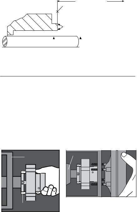
Seal Chamber Requirements |
Figure 1 |
|
|
|
|
To first obstruction
Face of seal housing to be square to the axis of the shaft to within 0.013 mm per millimeter (0.0005 inches) of seal chamber bore FIM and have a √1.6 μm (63 μinch) Ra finish or better
|
|
|
|
|
Gland pilot can be at either of these |
|||||
|
|
|
|
|
register locations, concentric to within |
|||||
|
Seal housing bore to have √3.2 μm |
0.13 mm (0.005 inch) FIM of shaft or sleeve OD |
||||||||
|
|
|
|
|
|
|
||||
|
(125 μinch) Ra finish or better |
|
|
|
|
|
|
|||
|
|
|
|
|
|
|
||||
Sleeve or shaft finish to be |
|
|
|
|
|
|
|
Shaft or sleeve OD |
||
|
|
|
|
|
|
|
+0.000 mm (+0.000 inch) |
|||
0.8 μm (32 μinch) Ra or better |
|
|
|
|
-0.050 mm (-0.002 inch) ANSI |
|||||
|
|
|
|
|
|
|
|
|
||
|
+0.000 mm (+0.000 inch) API 610/682 |
• Bearings must be in good condition |
-0.025 mm (- 0.001 inch) DIN/ISO |
• Maximum lateral or axial movement of shaft (end play) = 0.25 mm (0.010 inch) FIM |
|
• Maximum shaft runout at face of seal housing = 0.05 mm (0.002 inch) FIM |
|
• Maximum dynamic shaft deflection at seal housing = 0.05 mm (0.002 inch) FIM |
|
2 Uniseal Installation
Note: No seal setting measurements are needed to install the seal. Instructions are for end-suction back pull-out pumps. Modification of these procedures may be required for other style pumps. Consult Flowserve for installation support.
2.1Lubricate the shaft or pump sleeve lightly with silicone lubricant unless otherwise specified.
2.2Tighten the setting device cap screws to ensure they are tight before installation.
2.3Slide the Uniseal cartridge onto the shaft or pump sleeve with the setting devices toward the bearing housing. See Figure 2.
2.4Install the seal chamber and bolt it in place on the bearing frame. See Figure 3.
2.5Position the Uniseal with the gland tight against the seal chamber.
Bearing Frame |
Setting Device |
Figure 2
Bearing Housing
Seal
Chamber
Figure 3
3
 Loading...