


INNOMAG® U-MAG™
Horizontal close coupled, fluoropolymer lined, sealless chemical process pumps
PCN= 26999990 10-14 (E). Original instructions.
USER INSTRUCTIONS
Installation
Operation
Maintenance
 These instructions must be read prior to installing, operating, using and maintaining this equipment.

U-MAG ENGLISH 26999990 10-14
TABLE OF CONTENTS |
Page |
|||
1 |
INTRODUCTION AND SAFETY ........................ |
|
4 |
|
|
1.1 |
General ......................................................... |
|
4 |
|
1.2 |
CE marking and approvals ........................... |
|
4 |
|
1.3 |
Disclaimer ..................................................... |
|
4 |
|
1.4 |
Copyright....................................................... |
|
4 |
|
1.5 |
Duty conditions ............................................. |
|
4 |
|
1.6 |
Safety............................................................ |
|
5 |
|
1.7 |
Nameplate and safety labels ........................ |
|
9 |
|
1.8 |
Specific machine performance...................... |
|
9 |
|
1.9 |
Noise level .................................................... |
|
9 |
2 |
TRANSPORT AND STORAGE .......................... |
|
9 |
|
|
2.1 |
Consignment receipt and unpacking ............ |
|
9 |
|
2.2 |
Handling...................................................... |
|
10 |
|
2.3 |
Lifting........................................................... |
|
10 |
|
2.4 |
Storage........................................................ |
|
11 |
|
2.5 |
Recycling and end of product life................ |
|
11 |
3 |
DESCRIPTION ................................................ |
|
11 |
|
|
3.1 |
Configurations............................................. |
|
11 |
|
3.2 |
Nomenclature.............................................. |
|
11 |
|
3.3 |
Nameplate................................................... |
|
11 |
|
3.4 |
Design of major parts.................................. |
|
13 |
|
3.5 |
Performance and operating limits ............... |
|
13 |
4 |
INSTALLATION ................................................ |
|
14 |
|
|
4.1 |
Location ...................................................... |
|
14 |
|
4.2 |
Part Assemblies .......................................... |
|
14 |
|
4.3 |
Foundation .................................................. |
|
15 |
|
4.4 |
Grouting ...................................................... |
|
16 |
|
4.5 |
Piping .......................................................... |
|
17 |
|
4.6 |
Electrical connections ................................. |
|
18 |
|
4.7 |
Protection systems...................................... |
|
18 |
|
4.8 |
Final checks ................................................ |
|
19 |
5 COMMISSIONING, START-UP, OPERATION |
|
|||
|
AND SHUTDOWN ........................................... |
|
19 |
|
|
5.1 |
Direction of rotation..................................... |
|
19 |
|
5.2 |
Priming and auxiliary supplies .................... |
|
20 |
|
5.3 |
Starting the pump........................................ |
|
20 |
|
5.4 |
Running the pump....................................... |
|
20 |
|
5.5 |
Stopping and shutdown .............................. |
|
20 |
|
5.6 |
Hydraulic, mechanical and electrical duty .. |
21 |
|
6 |
MAINTENANCE............................................... |
|
21 |
|
|
6.1 |
General ....................................................... |
|
21 |
|
6.2 |
Maintenance schedule ................................ |
|
22 |
|
6.3 |
Spare parts.................................................. |
|
23 |
|
6.4 |
Tools required ............................................. |
|
23 |
|
6.5 |
Fastener torques......................................... |
|
23 |
|
6.6 |
Disassembly................................................ |
|
24 |
|
6.7 |
Examination of parts ................................... |
|
25 |
|
6.8 |
Casing [1100] Repair .................................. |
|
26 |
|
6.9 |
Containment Shell [3500] Repair ................ |
|
27 |
|
6.10 |
Impeller Repair............................................ |
|
27 |
|
6.11 |
Wet End Assembly...................................... |
|
29 |
Page 2 of 40
|
|
Page |
|
|
6.12 |
Drive End Disassembly .............................. |
29 |
|
6.13 |
Drive End Assembly ................................... |
30 |
|
6.14 |
Wet / Drive End Assembly .......................... |
32 |
|
6.15 |
Gasoline Engine ......................................... |
33 |
7 |
Troubleshooting ............................................... |
34 |
|
|
7.1 |
Faults, causes and remedies ..................... |
34 |
8 |
PARTS LISTS AND DRAWINGS..................... |
37 |
|
|
8.1 |
Sectional drawing ....................................... |
37 |
|
8.2 |
Parts interchangeability .............................. |
38 |
|
8.3 |
General arrangement drawing.................... |
39 |
9 |
CERTIFICATION ............................................. |
39 |
|
10 OTHER RELEVANT DOCUMENTATION AND |
|
||
|
MANUALS ....................................................... |
39 |
|
|
10.1 |
Supplementary User Instruction manuals .. |
39 |
|
10.2 |
Change notes ............................................. |
39 |
|
10.3 |
Additional sources of information ............... |
39 |

U-MAG ENGLISH 26999990 10-14
INDEX |
Page |
Page |
Additional information (10.3)................................. |
39 |
Assembly (6.11.2)................................................. |
29 |
ATEX marking (1.6.4.2) .......................................... |
7 |
CE marking and approvals (1.2) ............................. |
4 |
Certification (9) ...................................................... |
39 |
Change notes (10.2) ............................................. |
39 |
Commissioning and operation (5)......................... |
19 |
Compliance, ATEX (1.6.4.1) ................................... |
7 |
Configurations (3.1) .............................................. |
11 |
Copyright (1.4) ........................................................ |
4 |
Design of major parts (3.4) ................................... |
13 |
Direction of rotation (5.1) ...................................... |
19 |
Disassembly (6.6) ................................................. |
24 |
Disclaimer (1.3)....................................................... |
4 |
Drawings (8) ......................................................... |
37 |
Duty conditions (1.5)............................................... |
4 |
Electrical connections (4.6) .................................. |
18 |
End of product life (2.5) ........................................ |
11 |
Examination of parts (6.7)..................................... |
25 |
Fastener torques (6.5) .......................................... |
23 |
Faults, causes and remedies (7.1) ....................... |
34 |
Final checks (4.8) ................................................. |
19 |
Flange pressure rating (3.5.2) .............................. |
13 |
Foundation (4.3) ................................................... |
15 |
General (1.1)........................................................... |
4 |
General arrangement drawing (8.3) ..................... |
39 |
General assembly drawings (8)............................ |
37 |
Grouting (4.4) ........................................................ |
16 |
Handling (2.2) ....................................................... |
10 |
Hydraulic, mechanical and electrical duty (5.6) .... |
21 |
Inspection (6.7.2) .................................................. |
25 |
Installation (4) ....................................................... |
14 |
Lifting (2.3) ............................................................ |
10 |
Location (4.1)........................................................ |
14 |
Maintenance (6).................................................... |
21 |
Maintenance schedule (6.2) ................................. |
22 |
Name nomenclature (3.2) ..................................... |
11 |
Nameplate (1.7.1 and 3.3) ................................ |
9, 11 |
Page 3 of 40
Noise level (1.9) ...................................................... |
9 |
Nozzle loads (4.5.4) ............................................. |
18 |
Operating limits (3.5.1) ........................................ |
13 |
Ordering spare parts (6.3.1) ................................ |
23 |
Part assemblies (4.2) ........................................... |
14 |
Parts interchangeability (8.2) ............................... |
38 |
Parts lists (8) ........................................................ |
37 |
Performance (3.5) ................................................ |
13 |
Piping (4.5)........................................................... |
17 |
Priming and auxiliary supplies (5.2)..................... |
20 |
Protection systems (4.7) ...................................... |
18 |
Qualification and training (1.6.2)............................. |
5 |
Receipt and unpacking (2.1)................................... |
9 |
Recommended spares (6.3.3) ............................. |
23 |
Recycling (2.5) ..................................................... |
11 |
Replacement parts (6.3) ...................................... |
23 |
Running the pump (5.4) ....................................... |
20 |
Safety (1.6) ............................................................. |
5 |
Safety action (1.6.3)................................................. |
5 |
Safety markings (1.6.1) ............................................ |
5 |
Safety warnings (1) ................................................. |
4 |
Sectional drawing, general (8.1) .......................... |
37 |
Sectional drawings (8) ......................................... |
37 |
Shaft alignment check (4.8) ................................. |
19 |
Sources (10.3) ..................................................... |
39 |
Spare parts (6.3) .................................................. |
23 |
Specific machine performance (1.8) ....................... |
9 |
Starting the pump (5.3) ........................................ |
20 |
Stilt mounted baseplate (4.3.3.1) ......................... |
15 |
Stop/start frequency (5.4.2) ................................. |
20 |
Stopping and shutdown (5.5)............................... |
20 |
Storage (2.4) ........................................................ |
11 |
Storage of spares (6.3.2) ..................................... |
23 |
Supplementary user instructions (10.1) ............... |
39 |
ThermicSense (4.7.1.3) ....................................... |
19 |
Tools required (6.4) .............................................. |
23 |
Transport and storage (2) ....................................... |
9 |
Troubleshooting (7).............................................. |
34 |

1 INTRODUCTION AND SAFETY
1.1 General
 These instructions must always be kept close to the product's operating location or directly with the product.
Flowserve products are designed, developed and manufactured with state-of-the-art technologies in modern facilities. The unit is produced with great care and commitment to continuous quality control, utilizing sophisticated quality techniques and safety requirements.
Flowserve is committed to continuous quality improvement and being at service for any further information about the product in its installation and operation or about its support products, repair and diagnostic services.
These instructions are intended to facilitate familiarization with the product and its permitted use. Operating the product in compliance with these instructions is important to help ensure reliability in service and avoid risks. The instructions may not take into account local regulations; ensure such regulations are observed by all, including those installing the product. Always coordinate repair activity with operations personnel, and follow all plant safety requirements and applicable safety and health laws and regulations.
 These instructions must be read prior to installing, operating, using and maintaining the equipment in any region worldwide. The equipment must not be put into service until all the conditions relating to safety, noted in the instructions, have been met. Failure to follow and apply the present user instructions is considered to be misuse. Personal injury, product damage, delay or failure caused by misuse are not covered by the Flowserve warranty.
1.2 CE marking and approvals
It is a legal requirement that machinery and equipment put into service within certain regions of the world shall conform with the applicable CE Marking Directives covering Machinery and, where applicable, Low Voltage Equipment, Electromagnetic Compatibility (EMC), Pressure Equipment Directive (PED) and Equipment for Potentially Explosive Atmospheres (ATEX).
Where applicable, the Directives and any additional Approvals, cover important safety aspects relating to machinery and equipment and the satisfactory provision
Page 4 of 40
U-MAG ENGLISH 26999990 10-14
of technical documents and safety instructions. Where applicable this document incorporates information relevant to these Directives and Approvals.
To confirm the Approvals applying and if the product is CE marked, check the serial number plate markings and the Certification. (See section 9, Certification.)
1.3 Disclaimer
Information in these User Instructions is believed to be complete and reliable. However, in spite of all of the efforts of Flowserve Corporation to provide comprehensive instructions, good engineering and safety practice should always be used.
Flowserve manufactures products to exacting International Quality Management System Standards as certified and audited by external Quality Assurance organizations. Genuine parts and accessories have been designed, tested and incorporated into the products to help ensure their continued product quality and performance in use. As Flowserve cannot test parts and accessories sourced from other vendors the incorrect incorporation of such parts and accessories may adversely affect the performance and safety features of the products. The failure to properly select, install or use authorized Flowserve parts and accessories is considered to be misuse. Damage or failure caused by misuse is not covered by the Flowserve warranty. In addition, any modification of Flowserve products or removal of original components may impair the safety of these products in their use.
1.4 Copyright
All rights reserved. No part of these instructions may be reproduced, stored in a retrieval system or transmitted in any form or by any means without prior permission of Flowserve.
1.5 Duty conditions
This product has been selected to meet the specifications of your purchase order. The acknowledgement of these conditions has been sent separately to the Purchaser. A copy should be kept with these instructions.
 The product must not be operated beyond the parameters specified for the application.
If there is any doubt as to the suitability of the product for the application intended, contact Flowserve for advice, quoting the serial number.
If the conditions of service on your purchase order are going to be changed (for example liquid pumped, temperature or duty) it is requested that the user seeks the written agreement of Flowserve before start up.
1.6 Safety
1.6.1 Summary of safety markings
These User Instructions contain specific safety markings where non-observance of an instruction would cause hazards. The specific safety markings are:
 This symbol indicates electrical safety instructions where non-compliance will involve a high risk to personal safety or the loss of life.
 This symbol indicates safety instructions where non-compliance would affect personal safety and could result in loss of life.


 This symbol indicates “hazardous and toxic fluid” safety instructions where non-compliance would affect personal safety and could result in loss of life.
 This symbol indicates “Pacemaker” safety instructions where non-compliance would affect personal safety and could result in loss of life.
 This symbol indicates safety instructions where non-compliance will involve some risk to safe operation and personal safety and would damage the equipment or property.
 This symbol indicates explosive atmosphere zone marking according to ATEX. It is used in safety instructions where non-compliance in the hazardous area would cause the risk of an explosion.
 This symbol is used in safety instructions to remind not to rub non-metallic surfaces with a dry cloth; ensure the cloth is damp. It is used in safety instructions where non-compliance in the hazardous area would cause the risk of an explosion.
 This sign is not a safety symbol but indicates an important instruction in the assembly process.
1.6.2Personnel qualification and training
All personnel involved in the operation, installation, inspection and maintenance of the unit must be qualified to carry out the work involved. If the personnel in question do not already possess the necessary knowledge and skill, appropriate training and instruction must be provided. If required, the operator may
Page 5 of 40
U-MAG ENGLISH 26999990 10-14
commission the manufacturer/supplier to provide applicable training.
Always coordinate repair activity with operations and health and safety personnel. Follow all plant safety requirements and applicable safety and health laws and regulations.
1.6.3Safety action
This is a summary of conditions and actions to help prevent injury to personnel and damage to the environment and to equipment. For products used in potentially explosive atmospheres section 1.6.4 also applies.
 U-MAG™ pumps contain extremely strong permanent neodymium magnets which could affect the functioning of pacemakers and implanted heart defibrillators. If you wear these devices keep sufficient distance to magnets.
 Magnets produce a far-reaching, strong magnetic field. They can damage laptops, computer hard drives, credit and ATM cards, data storage media, mechanical watches, hearing aids and speakers. Keep magnets away from devices and objects that could be damaged by strong magnetic fields.
 NEVER DO MAINTENANCE WORK WHEN THE UNIT IS CONNECTED TO POWER
 GUARDS MUST NOT BE REMOVED WHILE THE PUMP IS OPERATIONAL


 DRAIN THE PUMP AND ISOLATE PIPEWORK BEFORE DISMANTLING THE PUMP
The appropriate safety precautions should be taken where the pumped liquids are hazardous.
 NEVER use heat (risk of explosion) to disassemble any portion of the pump.
 HIGH TEMPERATURES may be present. Pump surface temperature is directly related to the temperature of the working fluid. Never operate pump above the rated temperature of 121°C (250°F).

 HANDLING COMPONENTS
Many precision parts have sharp corners and the wearing of appropriate safety gloves and equipment is required when handling these components. To lift heavy pieces above 25 kg (55 lb.) use a crane appropriate for the mass and in accordance with current local regulations.

 Personal Protection Equipment suitable for the conditions and environment must be worn at all times.
 THERMAL SHOCK
Rapid changes in the temperature of the liquid within the pump can cause thermal shock, which can result in damage or breakage of components and should be avoided.
 HOT (and cold) PARTS
If hot or freezing components or auxiliary heating supplies can present a danger to operators and persons entering the immediate area action must be taken to avoid accidental contact. If complete protection is not possible, the machine access must be limited to maintenance staff only, with clear visual warnings and indicators to those entering the immediate area.
If the temperature is greater than 80 ºC (175 ºF) or below -5 ºC (23 ºF) in a restricted zone, or exceeds local regulations, action as above shall be taken.


 HAZARDOUS LIQUIDS
When the pump is handling hazardous liquids care must be taken to avoid exposure to the liquid by appropriate siting of the pump, limiting personnel access and by operator training. If the liquid is flammable and or explosive, strict safety procedures must be applied.
 PREVENT EXCESSIVE EXTERNAL PIPE LOAD. Do not use pump as a support for piping. Do not mount expansion joints, unless allowed by Flowserve in writing, so that their force, due to internal pressure, acts on the pump flange.
 Never loosen flange connection while system is under pressure.
 Always make certain pressure gages, indicating lights and safety devices are working.
 ALWAYS know the EMERGENCY STOP location for the pump.
Page 6 of 40
U-MAG ENGLISH 26999990 10-14
 NEVER RUN THE PUMP DRY. Use diamond-like-coated (DLC) parts for additional protection from dry running. DLC does not guarantee dry run protection.
 Never start this pump without proper prime (casing must be full of liquid).
 START THE PUMP WITH THE DISCHARGE VALVE PARTLY OPENED (Unless otherwise instructed at a specific point in the User Instructions.) This is recommended to minimize the risk of overloading and damaging the pump or motor at full or zero flow. Pumps may be started with the valve further open only on installations where this situation cannot occur. The pump outlet control valve may need to be adjusted to comply with the duty following the runup process. (See section 5, Commissioning start-up, operation and shutdown.)
 SUCTION VALVES TO BE FULLY OPEN WHEN PUMP IS RUNNING
Running the pump at zero flow or below the recommended minimum flow continuously will cause damage to the pump. Never operate this pump with the suction and / or discharge valve closed as this may lead to high surface temperatures.
 The direction of rotation is clockwise when viewed from the motor end. Rotation of the motor must be checked prior to starting the pump according to section 5.1.
 DO NOT RUN THE PUMP AT ABNORMALLY HIGH OR LOW FLOW RATES Operating at a flow rate higher than normal or at a flow rate with no back pressure on the pump may overload the motor and cause cavitation. Low flow rates may cause a reduction in pump/bearing life, overheating of the pump, instability and cavitation/vibration.
 NEVER EXCEED THE MAXIMUM DESIGN PRESSURE (MDP) AT THE TEMPERATURE SHOWN ON THE PUMP NAMEPLATE AND INCLUDED IN SECTION 3.5.2.
 Driver may overload and de-couple if pumpage specific gravity is greater than originally assumed. Prolonged running while de-coupled will damage driver and impeller magnets.
 Decoupling the pump may lead to increased surface temperatures.
 Never change conditions of service without approval of authorized Flowserve distributor.
 Excessive amounts of dust collected on the pump housing may lead to an increase in surface temperature, possibly exceeding temperature limits. May require regular cleaning.
Always have this service manual available during any installation or maintenance.
1.6.4 Products used in potentially explosive atmospheres
 Measures are required to:
Avoid excess temperature
Prevent build up of explosive mixtures
Prevent the generation of sparks
Prevent leakages
Maintain the pump to avoid hazard
The following instructions for pumps and pump units when installed in potentially explosive atmospheres must be followed to help ensure explosion protection. For ATEX, both electrical and non-electrical equipment must meet the requirements of European Directive 2014/34/EU (previously 94/9/EC which remains valid until April 20th 2016 during the transition). Always observe the regional legal Ex requirements eg Ex electrical items outside the EU may be required certified to other than ATEX eg IECEx, UL.
1.6.4.1Scope of compliance
 Use equipment only in the zone for which it is appropriate. Always check that the driver and pump equipment are suitably rated and/or certified for the classification of the specific atmosphere in which they are to be installed.
Where Flowserve has supplied only the bare shaft pump, the Ex rating applies only to the pump. The party responsible for assembling the ATEX pump set shall select the coupling, driver and any additional equipment, with the necessary CE Certificate/ Declaration of Conformity establishing it is suitable for the area in which it is to be installed.
The output from a variable frequency drive (VFD) can cause additional heating effects in the motor and so, for pumps sets with a VFD, the ATEX Certification for the motor must state that it is covers the situation where electrical supply is from the VFD. This particular requirement still applies even if the VFD is in a safe area.
Page 7 of 40
U-MAG ENGLISH 26999990 10-14
1.6.4.2Marking
An example of ATEX equipment marking is shown below. The actual classification of the pump will be engraved on the nameplate.
II 2 GD c IIC 135 ºC (T4)
Equipment Group
I = Mining
II = Non-mining
Category
2 or M2 = high level protection
3 = normal level of protection
Gas and/or dust
G = Gas
D = Dust
c = Constructional safety
(in accordance with EN13463-5)
Gas Group
IIA – Propane (typical)
IIB – Ethylene (typical)
IIC – Hydrogen (typical)
Maximum surface temperature (Temperature Class) (see section 1.6.4.3.)
1.6.4.3 Avoiding excessive surface temperatures
 ENSURE THE EQUIPMENT TEMPERATURE CLASS IS SUITABLE FOR THE HAZARD ZONE
Pumps have a temperature class as stated in the ATEX Ex rating on the nameplate. These are based on a maximum ambient of 40 ºC (104 ºF); refer to Flowserve for higher ambient temperatures.
The surface temperature on the pump is influenced by the temperature of the liquid handled. The maximum permissible liquid temperature depends on the ATEX temperature class and must not exceed the values in the table that follows.
Maximum permitted liquid temperature for pumps
Temperature class |
Maximum surface |
Temperature limit of |
to EN13463-1 |
temperature permitted |
liquid handled |
|
|
|
T6 |
85 °C (185 °F) |
65 °C (149 °F) * |
T5 |
100 °C (212 °F) |
80 °C (176 °F) * |
T4 |
135 °C (275 °F) |
115 °C (239 °F) * |
T3 |
200 °C (392 °F) |
180 °C (356 °F) * |
T2 |
300 °C (572 °F) |
275 °C (527 °F) * |
T1 |
450 °C (842 °F) |
400 °C (752 °F) * |
* The table only takes the ATEX temperature class into consideration. Pump design or material, as well as component design or material, may further limit the maximum working temperature of the liquid.

The temperature rise at the bearings and due to the minimum permitted flow rate is taken into account in the temperatures stated.
The operator is responsible to ensure that the specified maximum liquid temperature is not exceeded.
Temperature classification “Tx” is used when the liquid temperature varies and when the pump is required to be used in differently classified potentially explosive atmospheres. In this case the user is responsible for ensuring that the pump surface temperature does not exceed that permitted in its actual installed location.
Avoid mechanical, hydraulic or electrical overload by using motor overload trips, temperature monitors and/or a power monitor and make routine vibration monitoring checks.
In dirty or dusty environments, make regular checks and remove dirt from areas around close clearances, bearing housings and motors.
Where there is any risk of the pump being run against a closed valve generating high liquid and casing external surface temperatures fit an external surface temperature protection device.
1.6.4.4 Preventing the build-up of explosive mixtures
 ENSURE THE PUMP IS PROPERLY FILLED AND DOES NOT RUN DRY
Ensure the pump and relevant suction and discharge pipeline system is totally filled with liquid at all times during the pump operation, so that an explosive atmosphere is prevented.
If the operation of the system cannot avoid this condition, fit an appropriate dry run protection device (for example liquid detection or a power monitor).
To avoid potential hazards from fugitive emissions of vapor or gas to atmosphere the surrounding area must be well ventilated.
1.6.4.5Preventing sparks
 To avoid the potential hazard from random induced current generating a spark, the baseplate must be properly grounded.
Page 8 of 40
U-MAG ENGLISH 26999990 10-14
 Avoid electrostatic charge: do not rub non-metallic surfaces with a dry cloth; ensure cloth is damp.
Additional requirement for metallic pumps on non-metallic baseplates
When metallic components are fitted on a nonmetallic baseplate they must be individually earthed.
If so equipped, to prevent a potential hazard from mechanical contact, the coupling guard must be nonsparking. For ATEX the coupling must be selected to comply with European Directive 2014/34/EU (previously 94/9/EC which remains valid until April 20th 2016 during the transition). Correct coupling alignment must be maintained.
1.6.4.6Preventing leakage
 The pump must only be used to handle liquids for which it has been approved to have the correct corrosion resistance.
Avoid entrapment of liquid in the pump and associated piping due to closing of suction and discharge valves, which could cause dangerous excessive pressures to occur if there is heat input to the liquid. This can occur if the pump is stationary or running.
Bursting of liquid containing parts due to freezing must be avoided by draining or protecting the pump and ancillary systems.
If leakage of liquid to atmosphere can result in a hazard, install a liquid detection device or secondary containment.
1.6.4.7Maintenance to avoid the hazard
 CORRECT MAINTENANCE IS REQUIRED TO AVOID POTENTIAL HAZARDS WHICH GIVE A RISK OF EXPLOSION
The responsibility for compliance with maintenance instructions is with the plant operator.
To avoid potential explosion hazards during maintenance, the tools, cleaning and painting materials used must not give rise to sparking or adversely affect the ambient conditions. Where there is a risk from such tools or materials, maintenance must be conducted in a safe area.
It is recommended that a maintenance plan and schedule is adopted. (See section 6, Maintenance.)

1.7 Nameplate and safety labels
1.7.1Nameplate
For details of nameplate, see the Declaration of Conformity, or separate documentation included with these User Instructions.
1.7.2Safety labels
1.8 Specific machine performance
For performance parameters see section 1.5, Duty conditions. Where performance data has been supplied separately to the purchaser these should be obtained and retained with these User Instructions.
1.9 Noise level
Attention must be given to the exposure of personnel to the noise, and local legislation will define when guidance to personnel on noise limitation is required, and when noise exposure reduction is mandatory. This is typically 80 to 85 dBA. The usual approach is
Page 9 of 40
U-MAG ENGLISH 26999990 10-14
to control the exposure time to the noise or to enclose the machine to reduce emitted sound.
You may have already specified a limiting noise level when the equipment was ordered, however if no noise requirements were defined, then attention is drawn to the following table to give an indication of equipment noise level so that you can take the appropriate action in your plant.
Pump noise level is dependent on a number of operational factors, flow rate, pipework design and acoustic characteristics of the building, and so the values given are subject to a 3 dBA tolerance and cannot be guaranteed.
Similarly the motor noise provided in the table below is
“pump and motor” noise that is typically expected from standard and high efficiency motors when on load directly driving the pump. Note that a motor driven by an inverter may show an increased noise at some speeds.
If a pump unit only has been purchased for fitting with your own driver, then the noise levels in the table should be adjusted for the driver level obtained from the supplier. Consult Flowserve or a noise specialist if assistance is required in adjusting the values.
It is recommended that where exposure approaches the prescribed limit, then site noise measurements should be made. The values are in sound pressure level LpA at 1 m (3.3 ft) from the machine, for “free field conditions over a reflecting plane”.
Typical sound pressure level (Pump and Motor) LpA at 1 m (3.3 ft.) reference 20 μPa, dBA
Pump |
3550 |
2900 |
1750 |
1450 |
Series |
rpm |
rpm |
rpm |
rpm |
|
|
|
|
|
U-MAG™ |
75 |
69 |
65 |
60 |
|
|
|
|
|
Notes: (1.) values are for the maximum usable motor size (2.) for 1180 and 960 rpm reduce 1450 rpm values by 2 dBA. For 880 and 720 rpm reduce 1450 rpm values by 3 dBA. (3.) Choosing a fancooled motor will increase noise levels. (4.) Placing valves, orifices, or flow meters near a pump will increase noise levels inside the pump.
For estimating sound power level LWA (re 1 pW) then add 14 dBA to the sound pressure value.
2 TRANSPORT AND STORAGE
2.1 Consignment receipt and unpacking
Immediately after receipt of the equipment it must be checked against the delivery/shipping documents for
its completeness and that there has been no damage in transportation. Any shortage and/or damage must be reported immediately to Flowserve and must be received in writing within one month of receipt of the equipment. Later claims cannot be accepted.
Check any crate, boxes or wrappings for any accessories or spare parts that may be packed separately with the equipment or attached to side walls of the box or equipment.
Each pump/wet end has a unique serial number. Check that this number corresponds with that advised. Always use this number in correspondence and when ordering spare parts or further accessories.
2.2 Handling
Boxes, crates, pallets or cartons may be unloaded using fork lift vehicles or slings dependent on their size and construction.
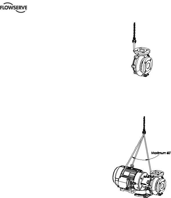
2.3 Lifting
U-MAG ENGLISH 26999990 10-14
Figure 2-1
2.3.2Lifting pump and motor assembly
For pump and motor, sling around the pump discharge nozzle, and around the outboard end of the motor frame using choker hitches pulled tight. The sling should be positioned so the weight is not carried through the motor fan housing. (Figure 2-2)
Figure 2-2
 A crane must be used for all pump sets or components in excess of 25 kg (55 lb.). Fully trained personnel must carry out lifting, in accordance with local regulations. Slings, ropes and other lifting gear should be positioned where they cannot slip and where a balanced lift is obtained. The angle between sling or ropes used for lifting must not exceed 60°.
 To avoid distortion, the pump unit should be lifted as shown.
 Pumps and motors often have integral lifting lugs or eye bolts. These are intended for use in only lifting the individual piece of equipment.
 Do not use eye bolts or cast-in lifting lugs to lift pump, motor and baseplate assemblies.
 Care must be taken to lift components or assemblies above the center of gravity to prevent the unit from flipping.
2.3.1Lifting Wet-End
The wet end should be lifted by sling around the pump discharge nozzle using a choker hitch pulled tight as shown in Figure 2-1.
Page 10 of 40
2.3.3 Lifting pump, motor and baseplate assembly
If the baseplate has lifting holes cut in the sides at the end (Type D, Type E bases and Type A when provided) insert lifting S hooks at the four corners and use slings or chains to connect to the lifting eye. Do not use slings through the lifting holes.
For other baseplates, sling around the pump discharge nozzle, and around the outboard end of the motor frame using choker hitches pulled tight. The sling should be positioned so the weight is not carried through the motor fan housing. (Figure 2-3)
U-MAG ENGLISH 26999990 10-14
Figure 2-3 |
2.5 Recycling and end of product life |
 Assembled units and their components are heavy. Failure to properly lift and support this equipment can result in serious physical injury and/or equipment damage. Lift equipment only at the specifically identified lifting points. Lifting devices such as eyebolts, slings, and spreaders must be rated, selected, and used for the entire load being lifted.
 Crush hazard. The unit and the components can be heavy. Use proper lifting methods and wear steeltoed shoes at all times.
 Do not attach sling ropes to shaft ends.
 Make sure that the unit cannot roll or fall over and injure people or damage property.
These pumps use carbon or ceramic silicon carbide components. Do not drop the pump or subject it to shock loads as this can damage the internal ceramic components.
2.4 Storage
 Store the pump in a clean, dry location away from vibration. Leave piping connection covers in place to keep dirt and other foreign material out of pump casing.
The pump may be stored as above for up to 6 months. Consult Flowserve for preservative actions when a longer storage period is needed.
Page 11 of 40
At the end of the service life of the product or its parts, the relevant materials and parts should be recycled or disposed of using an environmentally acceptable method and local requirements. If the product contains substances that are harmful to the environment, these should be removed and disposed of in accordance with current regulations.


 Make sure that hazardous substances are disposed of safely and that the correct personal protective equipment is used. The safety specifications must be in accordance with the current regulations at all times.
3 DESCRIPTION
3.1 Configurations
The U-MAG™ chemical process pumps are fluoropolymer lined, magnetically coupled, single stage, centrifugal pumps.
3.2 Nomenclature
The pump size will be etched on the nameplate as in this example: U012511100-UB0. See Figure 3-1 for pump identification codes.
3.3 Nameplate
Every U-MAGTM pump unit has a nameplate to provide information on your pump. The nameplates are located on the adapter with a second tag containing just the pump serial number affixed to the casing discharge flange. It is recommended that the purchaser record the serial number and use it for reference when requesting information, service, or parts from your supplier.
Permanent records for this pump are kept by the serial number and it, therefore, must be used with all correspondence and spare parts orders. Tag includes the following:
Pump Model Number: Example – U0
Pump Code: Example – U013711100-UB0
Serial Number: Example – 44001
Impeller Diameter / Max Impeller Diameter (mm or in.)
Duty Point (Flow/TDH)( m3/hr / m or US gpm / ft.)
Process Liquid Specific Gravity and Temperature (°C or °F)
Pump RPM / Pump power (kW or hp) @ Duty Point
Design Pressure (barg or psig) @ 38°C (100 °F)
Customer Pump Tag #
Process Liquid Being Pumped
Figure 3-1
U-MAG ENGLISH 26999990 10-14
The typical nomenclature above is the general guide to the U-MAG™ configuration description. Identify the actual pump size and serial number from the pump nameplate. Check that this agrees with the applicable certification provided.
U-MAGTM PUMP IDENTIFICATION CODE
|
|
|
|
Wet End |
|
|
|
|
|
|
|
|
U0 |
137 |
1 1 1 0 0 - |
||
|
|
|
|
|
|
|||
Models |
(Suction x Discharge x Nominal Impeller Diameter) |
|
|
|
||||
|
|
Size |
Min. |
Max. |
|
|
|
|
U0 |
- |
(1.5 x 1 x 5") |
3.25" |
6.13" |
|
|
|
|
|
|
(40 x 25 x 127mm) |
83 |
156 mm |
|
|
|
|
UL/UM/UN (1.5 x 1 x 5LF") |
3.25" |
6.13" |
|
|
|
|
||
|
|
(40 x 25 x 127mm) |
83 |
156 mm |
|
|
|
|
U1 |
- |
(2 x 1.5 x 6") |
3.25" |
6.13" |
|
|
|
|
|
|
(50 x 40 x 152mm) |
83 |
156 mm |
|
|
|
|
U3 |
- |
(3 x 2.5 x 6") |
4.50" |
6.13" |
|
|
|
|
|
|
(80 x 65 x 152mm) |
114 |
156 mm |
|
|
|
|
U4 |
- |
(2.5 x 2 x 6") |
3.50" |
6.13" |
|
|
|
|
|
|
(65 x 50 x 152mm) |
89 |
156 mm |
|
|
|
|
|
|
|
|
|
|
|
||
Impeller Diameter |
|
|
|
|
|
|
||
† 137 |
|
mm, divide by 25.4 for inches |
ex.137/25.4= |
5.39 in |
|
|||
† Impeller trim for U-MAGTM models must be specified in mm.
Bearing System |
|
|
|
|
|||
|
|
|
Bushing |
Shaft, Pump |
|
|
|
S |
0 |
- |
Carbon Graphite |
SiC |
|
|
|
$ |
1 |
- |
SiC |
SiC |
|
|
|
C$ |
2 |
- |
SiC + DLC |
SiC |
|
|
|
C$ |
4 |
- |
SiC - Spiral Groove |
SiC |
|
|
|
C$ |
6 |
- |
SiC - Grooved + DLC |
SiC |
|
|
|
|
|
|
|
|
|||
Wear Ring/Thrust Collar |
|
|
|
|
|||
|
|
|
Impeller |
Casing |
Containment Shell |
|
|
S |
0 |
- |
CF-PTFE |
SiC |
CF-PTFE |
|
|
$ |
1 |
- |
SiC |
SiC |
SiC |
|
|
|
|
|
|||||
Gasket |
(All Gaskets are 0.210" square cross section, equivalent to standard -363 O-Rings) |
|
|||||
S |
1 |
- |
FEP/FKM (Fluorocarbon) |
|
|
|
|
|
2 |
- |
FKM (Fluorocarbon) |
|
|
|
|
|
3 |
- |
EPDM (Ethylene Propylene) |
|
|
|
|
Flanges
S0 - ANSI/ISO/JIS (Universally Slotted)
1 - ANSI (Class 150)
2 - ISO (PN16)
3 - JIS (10kg/cm2) - JIS B2210 - 1989
Construction
|
|
Impeller |
Casing |
Retaining |
Casing |
Containment Shell |
|
|
Body |
Casting/Lining |
Rings |
Drain |
Lining/Composite |
S 0 |
- |
CF-ETFE |
D.I./ETFE |
CF-ETFE |
No |
CF-ETFE/Aramid |
1 |
- |
CF-ETFE |
D.I./ETFE |
CF-ETFE |
Yes |
CF-ETFE/Aramid |
C$$ 2 |
- |
PFA |
D.I./PFA |
PFA |
No |
PFA/Aramid |
U |
B |
0 |
Drive End |
|
|
|
|
|
|
|
|
Drive Torque Option |
||
|
|
0 |
- |
Standard Torque |
|
|
1 |
- |
High Torque |
|
|
|
|
|
|
|
Motor Frame |
||
|
NEMA C-Face |
|||
|
|
A |
- |
56C |
|
|
B |
- |
143/5 TC |
|
|
C |
- |
182/4 TC |
|
$t |
D |
- |
213/5 TC |
|
$t |
E |
- |
254/6 TC |
|
$Gt |
X |
- |
For 1" Shaft |
|
$Ht |
2 |
- |
For 1.25" hydraulic motor |
|
IEC B5 |
|
|
|
|
|
M |
- |
80 |
|
|
N |
- |
90S/L |
|
|
P |
- |
100L/112M |
|
$t |
R |
- |
132 |
Product Group
U - U-MAGTM
Notes:
Material Guide:
CF - Carbon Fiber
D.I. - Ductile Iron
ETFE - Ethylenetetrafluoroethylene
PTFE - Polytetrafluoroethylene
PFA - Perfluoroalkoxy
SiC - Silicon Carbide (Ceramic)
S Standard Material/Options
C Consult Factory for Availability t High Torque Option
$ Price Adder
GGas Engine Motor
HHydraulic Motor (SAE)
Rev. Date 4/17/2014
Not an exhaustive list. Available options subject to change without notice. Consult factory for availability and pricing.
Page 12 of 40
 Loading...