


Installation
Instructions
Durametallic® P-200
Cartridge dual pusher seal for standard and big bore ANSI pumps
Experience In Motion
Description
This P-200 seal is a dual, cartridge mounted, end face mechanical seal, designed for ease of installation. No seal setting dimensions are required. Removable setting devices provide proper alignment.
Installation according to the following steps will ensure a long trouble-free life of the P-200 seal.
1 Equipment Check
1.1Follow plant safety regulations prior to equipment disassembly:
•Lock out motor and valves.
•Wear designated personal safety equipment.
•Relieve any pressure in the system.
•Consult plant MSDS files for hazardous material regulations.
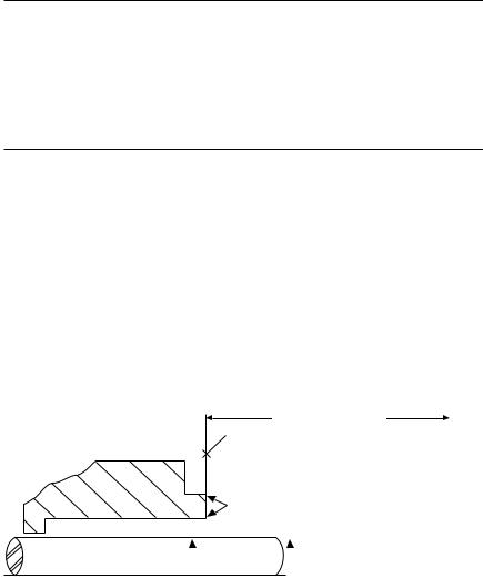
Seal Chamber Requirements |
Figure 1 |
To first obstruction
Face of seal housing to be square to the axis of the shaft to within 0.0005 mm/mm (0.0005 inch/inch) of seal chamber bore TIR
and have a 1.6 μm (63 μinch) Ra finish or better
|
|
|
|
|
|
Gland pilot can be at either of these |
|
|||||
|
|
|
|
|
|
register locations, concentric to within |
|
|||||
|
|
|
|
|
|
0.125 mm (0.005 inch) of shaft or |
|
|||||
|
|
Seal housing bore to have 3.2 μm |
sleeve OD TIR |
|
||||||||
|
|
(125 μinch) Ra finish or better |
|
|
|
|
|
|
|
|||
|
Sleeve or shaft finish to be |
|
|
|
|
|
|
|
Shaft or sleeve OD |
|
||
|
|
|
|
|
|
|
|
+0.000 mm (+0.000 inch) |
ANSI |
|||
|
0.8 μm (32 μinch) Ra or better |
|
|
|
|
-0.050 mm (-0.002 inch) |
||||||
|
|
|
|
|
|
|
|
|
|
|
||
|
|
|
|
|
|
|
|
|
|
+0.000 mm (+0.000 inch) |
API 610/682 |
|
• Bearings must be in good condition |
|
|
|
|
-0.025 mm (-0.001 inch) |
DIN/ISO |
||||||
• Maximum lateral or axial movement of shaft (end play) = 0.25 mm (0.010 inch) TIR |
|
|||||||||||
• Maximum shaft runout at face of seal housing = 0.05 mm (0.002 inch) TIR |
|
|||||||||||
• Maximum dynamic shaft deflection at seal housing = 0.05 mm (0.002 inch) TIR |
|
|||||||||||
|
The images of parts shown in these instructions may differ visually from the actual |
2 |
parts due to manufacturing processes that do not affect the part function or quality. |
|
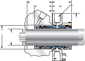
P-200 Dimensional Data |
|
|
|
|
|
|
|
Figure 2 |
||||||||||||
|
|
|
C |
|
|
|
|
|
|
|
|
|
E |
|
2 G NPT for |
|||||
|
|
|
|
|
|
|
|
|
|
|
||||||||||
|
|
|
|
|
D |
|
|
|
|
|
|
|
|
|
F |
|
|
|
|
|
|
|
|
|
|
|
|
|
|
|
|
|
|
|
|
|
|||||
|
|
|
|
|
|
|
|
|
|
|
|
|
|
|
|
|
sealing fluid inlet |
|||
|
|
|
|
|
|
|
|
|
|
|
|
|
|
|
.03 |
|
|
|
and outlet. |
|
|
|
|
|
|
|
|
|
|
|
|
|
|
|
|
||||||
K |
ø |
B A
Shaft & Seal
Size
G NPT marked "Flush" should be 


 plugged when not used for flushing
Dimensional Data for P-200 Seal, inch
4 H ø studs equally spaced on J BC
A |
B |
B |
C |
D |
E |
F |
G |
H |
J |
K |
Shaft & |
Box Bore |
Box Depth |
Seal |
Seal |
Gland |
NPT |
Bolt Dia. |
Bolt Circle |
Gland OD |
|
Seal Size |
(Min) |
(Max) |
(Min) |
Depth |
Extension Thickness |
|
(Max) |
(Max) |
(Min) |
|
|
|
|
|
|
|
|
|
|
|
|
1.000 |
1.750 |
1.875 |
1.78 |
1.69 |
2.00 |
1.02 |
0.375 |
0.375 |
2.75 |
3.75 |
1.125 |
1.750 |
2.000 |
1.78 |
1.69 |
2.00 |
1.02 |
0.375 |
0.500 |
3.00 |
3.88 |
1.250 |
2.000 |
2.125 |
1.97 |
1.88 |
2.00 |
1.02 |
0.375 |
0.500 |
3.12 |
4.25 |
1.375 |
2.000 |
2.250 |
1.97 |
1.88 |
2.00 |
1.02 |
0.375 |
0.375 |
3.25 |
4.25 |
1.500 |
2.250 |
2.500 |
1.97 |
1.88 |
2.00 |
1.02 |
0.375 |
0.375 |
3.75 |
4.75 |
1.625 |
2.375 |
2.625 |
1.97 |
1.88 |
2.00 |
1.02 |
0.375 |
0.500 |
3.75 |
4.75 |
1.750 |
2.500 |
2.750 |
1.97 |
1.88 |
2.00 |
1.02 |
0.375 |
0.500 |
3.75 |
5.00 |
1.875 |
2.625 |
2.875 |
1.97 |
1.88 |
2.00 |
1.02 |
0.375 |
0.500 |
3.88 |
5.00 |
2.000 |
2.750 |
3.000 |
1.97 |
1.88 |
2.00 |
1.02 |
0.375 |
0.625 |
4.12 |
5.12 |
2.125 |
2.875 |
3.250 |
1.97 |
1.88 |
2.00 |
1.02 |
0.375 |
0.625 |
4.38 |
6.00 |
2.250 |
3.000 |
3.375 |
1.97 |
1.88 |
2.00 |
1.02 |
0.375 |
0.625 |
4.62 |
6.50 |
2.375 |
3.250 |
3.625 |
2.16 |
2.06 |
2.09 |
1.11 |
0.375 |
0.625 |
5.00 |
6.38 |
2.500 |
3.375 |
3.750 |
2.16 |
2.06 |
2.09 |
1.11 |
0.375 |
0.625 |
5.00 |
6.62 |
2.625 |
3.500 |
3.875 |
2.16 |
2.06 |
2.09 |
1.11 |
0.375 |
0.750 |
5.75 |
7.25 |
2.750 |
3.750 |
4.062 |
2.16 |
2.06 |
2.62 |
1.58 |
0.500 |
|
|
|
2.875 |
3.875 |
4.187 |
2.16 |
2.06 |
2.62 |
1.58 |
0.500 |
The bolt diameter, bolt |
||
3.000 |
4.000 |
4.312 |
2.16 |
2.06 |
2.62 |
1.58 |
0.500 |
|||
3.125 |
4.250 |
4.562 |
2.16 |
2.06 |
2.62 |
1.58 |
0.500 |
circle and gland OD for |
||
shaft and seal sizes |
||||||||||
3.250 |
4.375 |
4.687 |
2.28 |
2.19 |
2.75 |
1.71 |
0.500 |
2.750 inches through |
||
3.375 |
4.500 |
4.812 |
2.28 |
2.19 |
2.75 |
1.71 |
0.500 |
3.875 inches will be |
||
determined by equipment |
||||||||||
3.500 |
4.625 |
4.937 |
2.28 |
2.19 |
2.75 |
1.71 |
0.500 |
requirements. |
|
|
3.625 |
4.750 |
5.062 |
2.28 |
2.19 |
2.75 |
1.71 |
0.500 |
|
|
|
3.750 |
4.875 |
5.187 |
2.28 |
2.19 |
2.75 |
1.71 |
0.500 |
|
|
|
3.875 |
5.000 |
5.312 |
2.28 |
2.19 |
2.75 |
1.71 |
0.500 |
|
|
|
* This seal size uses the N-CBR inner seal rotary unit.
† Preferred design for these shaft sizes. Use whenever possible.
3
1.2Disassemble equipment in accordance with equipment manufacturer’s instructions to allow access to seal installation area.
1.3Remove existing mechanical seal and gland or compression packing and packing gland (follower flange).
1.4Make sure the shaft or sleeve is free of burrs, cuts, dents or corrosion that might cause leakage past the sleeve gasket, as shown on the assembly drawing. Replace worn shaft or sleeve.
Remove sharp edges from keyways and threads.
1.5Make sure the seal housing face is clean and free of burrs, cuts, dents or corrosion that might cause leakage at the gland gasket or misalign the seal gland.
1.6Check equipment dimensions to ensure they are within the dimensions shown in Figures 1 and 2. Critical dimensions include shaft or sleeve OD (A), chamber depth (C), minimum and maximum seal housing bore (B), and the minimum distance to the first obstruction (E) plus 3.175 mm (0.125 inch).
1.7Check gland bolting to ensure that bolt diameter (H) and bolt circle (J) conform to the dimensions shown in Figure 2.
1.8Handle the P-200 seal with care, it is manufactured to precise tolerances. The sealing faces of the rotating face and stationary face are of special importance. They are lapped flat to within three light bands (34.8 millionths of an inch). Keep the seal faces perfectly clean at all times.
4
 Loading...