


L120-85
Experience In Motion
USER INSTRUCTIONS
Installation
Operation
Maintenance
Limitorque L120-85 Actuator
FCD LMENIM1202-00 – 11/05

L120-85 Actuator
Installation and Maintenance Manual
©2005 Copyright Flowserve Corporation. All rights reserved.
Printed in the United States of America.
Disclaimer
No part of this book shall be reproduced, stored in a retrieval system, or transmitted by any means, electronic, mechanical, photocopying,
recording, or otherwise without the written permission from Flowserve. While every precaution has been taken in the preparation of the
book, the publisher assumes no responsibility for errors or omissions. Neither is any liability assumed for damages resulting from the use of
the information contained herein.
This document is proprietary information of Flowserve furnished for customer use ONLY. No other uses are authorized without written
permission of Flowserve.
Flowserve reserves the right to make changes, without notice, to this document and the products it describes. Flowserve shall not be liable
for technical or editorial errors or omissions made herein; nor for incidental or consequential damages resulting from the furnishing, perfor-
mance or use of this document.
This manual contains information that is correct to the best of Flowserve’s knowledge. It is intended to be a guide and should not be consid-
ered as a sole source of technical instruction, replacing good technical judgment, since all possible situations cannot be anticipated. If there
is any doubt as to exact installation, configuration, and/or use, please contact Flowserve at 1-800-225-6989.
The choice of system components is the responsibility of the buyer, and how they are used cannot be the liability of Flowserve Corporation.
However, Flowserve’s sales team and application engineers are always available to assist you in making your decision.
Belden
®
is a registered trademark of Belden, a division of Cooper Industries, Inc.
Limitorque L120-85 Installation, Operation and Maintenance FCD LMENIM1202-00 – 11/05
2

1.1 Purpose 5
1.2 User Safety
5
2.1 Product Identification
7
2.2 Product Description
8
2.3 Product Features
8
4.1 Safety 1
1
4.2 Initial Actuator Preparation 1
1
4.2.1 Inspection and Recording 1
1
4.2.2 Short-Term Storage (less than one year) 1
1
4.3 Actuator Mounting 1
2
4.3.1 Torque Only Applications (Drive 1) 1
2
4.3.2 Torque and Thrust Applications
(Drive 2) 12
4.3.3 Mounting Bolts 1
3
4.3.4 Stem Cover for Rising Stem Applications 1
3
4.4 Verifying Motor Rotation Direction 1
4
4.4.1 Initial Electrical Connections 1
4
4.4.2 Motor rotation (phasing)
and OPEN/CLOSE pushbutton operation. 15
4.4.3 Three-Phase Motor 1
5
4.4.4 DC Motor 1
5
4.5 Limit Switch Settings 1
5
4.5.1 Basic Theory of Operation 1
6
4.5.2 Adjustment—General 1
7
4.5.3 Setting the OPEN Limit Switch 1
7
4.5.4 Setting the CLOSE Limit Switch 1
8
4.6 Torque Switch Setting and Wiring 1
9
4.6.1 Basic Theory of Operation 1
9
4.6.2 Setting the Torque Switch 1
9
4.6.3 Balancing the Torque Switch 1
9
4.6.4 Rewiring the Torque Switch
for Non-Standard Drive Sleeve Rotation 20
4.7 Position Indication 2
0
4.7.1 Local Position Indication 2
0
4.7.2 Remote Position Indication 2
1
4.7.3 Setting the Potentiometer 2
2
5.1 Description of Motor Operation 2
3
5.2 Description of Manual Operation 2
3
6.1 Lubrication 2
5
6.1.1 Initial Inspection 2
5
6.1.2 Frequency 2
5
6.1.3 Routine Inspection 2
5
6.1.4 Factory Lubricants 2
5
6.1.5 Minimum Lubricant Qualities Required 2
6
8.1 Handwheel Shaft Assembly and Shimming 3
1
8.2 Verifying Handwheel Operation 3
3
8.3 Thrust Base Assembly and Shimming 3
3
9.1 Typical Wiring Diagram 3
7
Three-phase with Control Package 3
7
10.1 L120-85 Illustrated Parts Breakdown 4
0
10.2 L120-85 Parts List 4
5
Contents
3
Limitorque L120-85 Installation, Operation and Maintenance FCD LMENIM1202-00 – 11/05
flowserve.com

Figures
Figure 1: Limitorque L120-85 Actuator 8
Figure 2: L120-85 Torque Drive Nut and Retaining Ring Details 1
2
Figure 3: Thrust Base removal from an L120-85 1
2
Figure 4: L120-85 Torque Drive Nut orientation (Drive 1) 1
3
Figure 5: L120-85 Thrust Base Assembly orientation (Drive 2) 1
4
Figure 6: Electrical Compartment and Conduit Pipe Plug openings 1
4
Figure 7: Grounding Lug location 1
5
Figure 8: Limit Switch Rotor development 1
6
Figure 9: L120-85 Limit Switch Components 1
7
Figure 10: Limit Switch OPEN/CLOSED Rotor Cam orientation 1
8
Figure 11: Torque Switch Components 1
9
Figure 12: Reversing Torque Switch wiring 2
0
Figure 13: Aligning MDPI Pointer for Fully CLOSED Position 2
0
Figure 14: Remote Position Indicator Calibration Configuration 2
1
Figure 15: Potentiometer Calibration configuration 2
2
Figure 16: Loosening Potentiometer Assembly 2
2
Figure 17: Removing Clutch Pinion Assembly 2
9
Figure 18: Key components affected by Handwheel shimming 3
1
Figure 19: Cut-away view of L120-85 actuator
with Clutch Latch positioned on face of Clutch Bearing 3
2
Figure 20: Gap between Housing face and Handwheel Bushing
shown as dimension “A” 3
2
Figure 21: Shimming parts and their order of assembly 3
3
Figure 22: Shim location for gap “B” dimension/ 3
3
Figure 23 Three-phase with Control Package 3
7
Figure 24: Electrical Compartment 4
0
Figure 25: Motor and Motor Drive Components 4
1
Figure 26: Handwheel Shaft and Associated Components 4
2
Figure 27: Drive Sleeve Group 4
3
Figure 28: Thrust Base Group 4
4
Tables
Table 1: L120-85 Approximate Weight Chart 9
Table 2: Torque Drive Nut: Maximum Allowable
Bore and Key Sizes 1
2
Table 3: L120-85 Actuator/Mounting Base Tap Size 1
3
Table 4: Gap “A” shim thickness selection chart 3
2
Table 5: Gap “B” shim thickness selection chart 3
3
Limitorque L120-85 Installation, Operation and Maintenance FCD LMENIM1202-00 – 11/05
4

1.1 Purpose
This Installation and Maintenance Manual explains how to install and
maintain the L120-85 actuator. Information is provided for installa-
tion, disassembly, reassembly, lubrication, and parts selection.
c
WARNING: Read this installation and maintenance man-
ual carefully and completely before storing, installing,
operating or troubleshooting your Flowserve Limitroque
actuator. Be aware of electrical hazards within the actua-
tor and high-pressure hazards at the attached valve or
other device when installing or performing maintenance
on your L120-85 actuator.
1.2 User Safety
Safety notices in this manual detail precautions the user must take
to reduce the risk of personal injury and damage to the equipment.
The user must read and be familiar with these instructions before
attempting installation, operation, or maintenance. Failure to observe
these precautions could result in serious bodily injury, damage to the
equipment, voiding of the warranty, or operational difficulty.
Safety notices are presented in this manual in three forms:
c
WARNING: Refers to personal safety. Alerts the user to
potential danger. Failure to follow warning notices could
result in personal injury or death.
a
CAUTION: Directs the user’s attention to general precautions
that, if not followed, could result in personal injury and/or
equipment damage.
NOTE:
Highlights information critical to the user’s understanding of
the actuator’s installation and operation.
1
Introduction
5
Limitorque L120-85 Installation, Operation and Maintenance FCD LMENIM1202-00 – 11/05
flowserve.com

Limitorque L120-85 Installation, Operation and Maintenance FCD LMENIM1202-00 – 11/05
6

2.1 Product Identification
The actuator unit nameplate is located on the back of the unit,
opposite the limit switch compartment. The nameplate contains the
following information:
• Product name
• Point of Manufacture
• Unit Size
• Order Number
• Serial Number
• Customer Tagging
• Certification Information
The motor nameplate is located on the motor. The nameplate con-
tains the following information:
• ID Number
• Run Torque
• RPM
• Full Load Amps
• Insulation Class
• Horsepower
• Number of Phases
• Motor Code
• Connection Diagram
• Start Torque
• Enclosure Type
• Volts
• Locked Rotor Amps
• Duty Rating
• Service Factor
• Frequency
• Ambient Temperature
2
Product Capabilities and Features
7
Limitorque L120-85 Installation, Operation and Maintenance FCD LMENIM1202-00 – 11/05
flowserve.com
2.2 Product Description
Your L120-85 actuator controls the opening and closing travel of
valves or other actuated devices. OPEN and CLOSED limits are
protected by Limit Switches and output torque is measured and
protected by the Torque Switches. As a result, all valves and other
actuated devices are protected from potential damage from overload,
improper seating and foreign obstructions.
Limitorque actuators may be mounted on any appropriately sized
valve in almost any position or location.
Microprocessor-based controls and monitoring devices are also
available for installation on your actuator. Contact your local Limi-
torque distributor or Limitorque sales office for further information.
2.3 Product Features
• Up to 850 ft-lb/1156 Nm torque capacity.
• Up to 45,000 lb./20250 kg thrust capacity.
• Up to 3.25"/76 mm threaded stem capacity.
• Up to 2.75"/70 mm bore capacity.
• Torque Only (Drive 1) or Torque and Thrust (Drive 2) actuators,
with removable ductile iron thrust base assembly.
• Torque unit can be removed from thrust base while valve position
is maintained.
• Standard cast iron gear case.
• All power gearing supported on anti-friction bearings.
• All gearing is alloy, heat-treated steel or bronze.
• Speed range of 24-192 RPM (60 Hz), 20-160 RPM (50 Hz).
• Declutch force independent of load on valve stem.
• Self-locking gearing available.
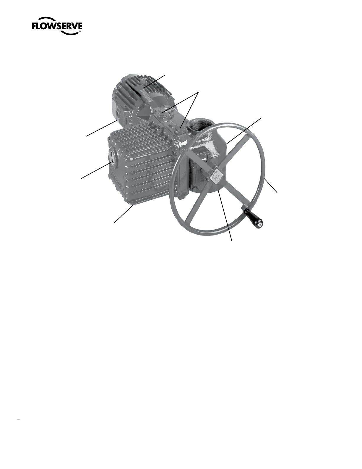
Figure 1: Limitorque L120-85 Actuator
Thrust
Base
Handwheel
Electrical
Compartment
Cover
Conduit
Openings
(plugged; two additional openings
are supplied on the bottom of the
Electrical Compartment)
Housing
Declutch
Lever
Motor
Position
Indication
Window
Limitorque L120-85 Installation, Operation and Maintenance FCD LMENIM1202-00 – 11/05
8

The following table is an L120-85 representative weight chart. It
provides the weight of several components that may be incorporated
into a typical package. Use the chart as a guideline to estimate the
weight of your particular actuator package.
Table 1: L120-85 Approximate Weight Chart
Components lb. kg
L120-85 with 40 ft-lb 1700 RPM Motor 253 558
18" Handwheel 7 15
Handwheel Adapter 5 11
Minimum Integral Control
Package and Compartment
34 75
Thrust Base Assembly (Drive 2) 67 148
Total Weight 366 lb. 807 kg
3
Unit Weight
9
Limitorque L120-85 Installation, Operation and Maintenance FCD LMENIM1202-00 – 11/05
flowserve.com

Limitorque L120-85 Installation, Operation and Maintenance FCD LMENIM1202-00 – 11/05
10

4.1 Safety
c
WARNING: Read this Installation and Maintenance
Manual carefully and completely before attempting to
store, install, operate or troubleshoot your Limitorque
valve actuator. Be aware of electrical hazards within the
actuator and high pressure hazards of the attached valve
or other actuated device when installing or performing
maintenance on your L120-85 actuator.
4.2 Initial Actuator Preparation
4.2.1 Inspection and Recording
Upon receipt of the actuator, several steps should be initially fol-
lowed to ensure condition of equipment and to establish proper
record keeping.
1. Carefully remove actuator from shipping carton or skid.
Thoroughly examine for any physical damage which may have
occurred during shipment. If you note any damage, immediately
report the damage to the transport company.
2. A nameplate with important information is attached to each
actuator. Record this information for future reference.
4.2.2 Short-Term Storage
(less than one year)
Units are not weatherproof until properly installed on the valve or
prepared for storage.
Store units in a clean, dry, protected warehouse away from excessive
vibration and rapid temperature changes. If the units must be stored
outside, they must be stored off the ground, high enough to prevent
them from being immersed in water or buried by snow.
1. Position the actuator in storage with motor and switch compart
-
ment horizontal.
2. Connect the internal heaters (if supplied) or place desiccant in
the switch compartment.
3. Replace all plastic caps or plugs with taped or doped pipe plugs
and ensure that all covers are tight.
4. If the actuator is mounted on a valve and the stem protrudes
from the unit, a suitable stem cover must be provided.
4
Initial Preparation and Installation
11
Limitorque L120-85 Installation, Operation and Maintenance FCD LMENIM1202-00 – 11/05
flowserve.com
NOTE: If your unit incorporates a rising stem application, it may be
shipped with a plastic cap over the Drive Sleeve Housing. If so, in
order to store without possible corrosion occurring, install a pipe
plug or protective stem cover to protect the Drive Sleeve Housing.
NOTE: Failure to comply with recommended storage procedures
could cause the warranty to be voided. For long-term storage proce-
dures, consult the Limitorque Customer Service Department.
4.3 Actuator Mounting
Your L120-85 is designed to perform actuation for torque only
applications (drive 1) or for torque and thrust applications (drive
2). If you are using a torque only configuration, before installing on
the valve or other actuated device, you will need to verify that the
Torque Drive Nut (piece 95) is properly bored and keyed to fit your
valve stem. If you are using a torque and thrust configuration, you
will need to verify that the Thrust Base Drive Sleeve (piece 101) is
properly threaded to fit your threaded valve stem. Use the following
procedures to check for proper fit of the Torque Drive Nut or the
Thrust Base Drive Sleeve.
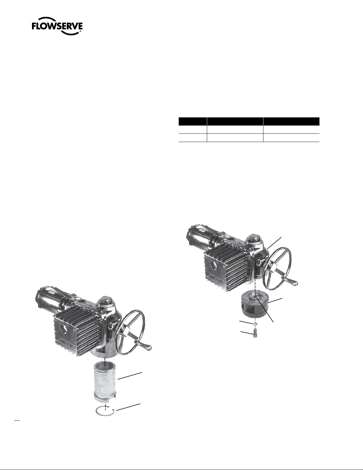
4.3.1 Torque Only Applications (Drive 1)
(Refer to Figure 27)
Remove the Torque Nut Retaining Ring (piece 98) and Torque Drive
Nut (piece 95) from actuator.
Figure 2: L120-85 Torque Drive Nut and Retaining Ring Details
#95 Torque
Drive Nut
#98 Torque Nut
Retaining Ring
A) If Torque Drive Nut has been bored and keywayed by supplier,
verify dimensions of keyway for proper compatibility with the
valve stem.
B) If Torque Drive Nut has not been bored and keywayed by sup
-
plier, it is provided solid (blank) to allow customer to custom
bore and key up to the maximum permissible sizes as listed:
Table 2: Torque Drive Nut: Maximum Allowable Bore and Key Sizes
Key Type Maximum Bore in. (mm) Maximum Key in. (mm)
Rectangle 2.750 (69.85) .625 x .4375 (20 x 12)
Square 2.625 (66.67) .625 x .625 (20 x 20)
4.3.2 Torque and Thrust Applications
(Drive 2) (Refer to Figure 28)
Remove Socket Head Cap Screw (piece 110) and Lockwasher (piece
111) that holds the Thrust Base Housing Assembly to the actuator
Housing (piece 1).
Figure 3: Thrust Base removal from an L120-85
#111 Lockwasher
#110 Socket Head
Cap Screw
#100 Thrust Base
Housing
#1 Housing
#101 Thrust Base
Drive Sleeve
A) If the Thrust Base Drive Sleeve (piece 101) has been threaded by
supplier, verify thread compatibility with the threaded Valve Stem
by screwing Drive Sleeve onto the valve stem.
B) If Thrust Base Drive Sleeve (piece 101) has not been threaded by
supplier, it is provided solid (blank) to allow customer to custom
thread. Maximum threaded stem diameter is 3.25" (82.5 mm).
NOTE: If Thrust Base disassembly is required in order to thread
blank Thrust Base Drive Sleeve, remove Quad Rings (piece 107)
before removing Thrust Washer (piece 104) and Thrust Bearing
Limitorque L120-85 Installation, Operation and Maintenance FCD LMENIM1202-00 – 11/05
12
(piece 103). This will prevent damaging the Quad Rings (piece 107).
For details refer to Section 10.1, Figure 28.
4.3.3 Mounting Bolts
Mount the L120-85 actuator on the Actuator Mounting Adapter
(Drive 1) or on the Thrust Base Assembly (Drive 2). High-strength
(minimum hex head SAE-Grade 5 or ISO Metric Class socket head
cap screws) 8.8 hex head or socket head cap screws with lockwash-
ers are recommended. The quantity and thread size of the actuator
mounting taps are as follows:
Table 3: L120-85 Actuator/Mounting Base Tap Size
Unit Type Quantity Tap Size
Drive 1 and 2
English 4 ¾–10 Tap x 1.0 in. Deep*
Metric 4 M20 x 2.5 mm x 10 mm Deep*
*Complies with F16 IOS mounting flange criteria
NOTE: Limitorque has supplied four taps for the L120-85 English
and metric units. All four securing bolts are required to retain torque
and/or thrust reaction on these units.
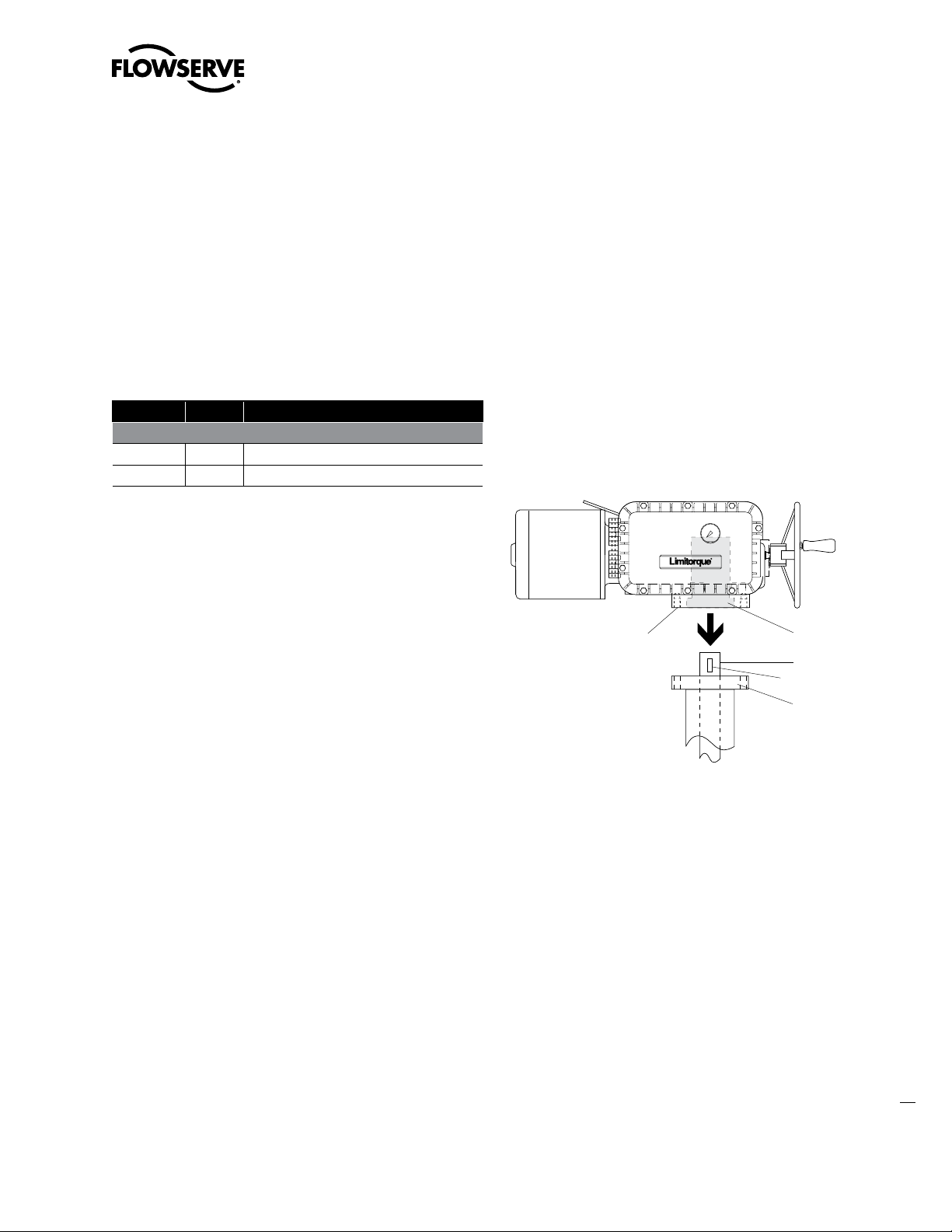
4.3.4 Stem Cover for Rising Stem
Applications
a
CAUTION: Selection and installation of a stem cover which is
too short will result in damage to the valve and/or actuator.
a
CAUTION: Be sure to complete each step of the installation
overview before electrically operating your actuator. If your
actuator is already mounted to a valve or other actuated
device from the manufacturer, verify that the actuator is
mounted according to the following overview. Failure to
follow the installation procedures could result in personal
injury or may allow the actuator to operate improperly and
could cause damage to your equipment.
a
CAUTION: Ensure Retaining Ring (piece 98) is properly
engaged in the Drive Sleeve (piece 25) to secure the Torque
Drive Nut (piece 95) in place. If the Torque Drive Nut is not
properly secured, it may fall from the bottom of the actuator
when removed from customer mounting adapters.
Before putting your actuator into operational service, check the
height of your valve stem at the full OPEN position and mount a
suitable stem cover to protect the valve stems and to prevent water
entry into the actuator.
Installation Overview
1. Applications
A. Torque Only Applications (Drive 1)
Mount Torque Drive Nut (piece 95) in the actuator with the
Torque Drive Nut axially aligned on the Drive Sleeve (piece
25) so that the bottom of the nut is positioned inside the
actuator Mounting Base. Secure Torque Drive Nut inside
Drive Sleeve (piece 25) with Retaining Ring (piece 98). Refer
to Figure 27.
B. Torque and Thrust Applications (Drive 2)
Screw the Thrust Base Assembly onto the Threaded Valve
Stem and secure the Thrust Base Assembly to the Actuator
Mounting Base using Socket Head Cap Screws (piece 110)
and Lockwashers (piece 111).
Figure 4: L120-85 Torque Drive Nut orientation (Drive 1)
Drive 1
Actuator
Mounting
Base
Actuator
Mounting
Adapter
Valve
Stem
#95 Torque
Drive Nut
Key
Note: Key is shown for reference.
It may be in one of several other
orientations in reference to the
actuator.
13
Limitorque L120-85 Installation, Operation and Maintenance FCD LMENIM1202-00 – 11/05
flowserve.com
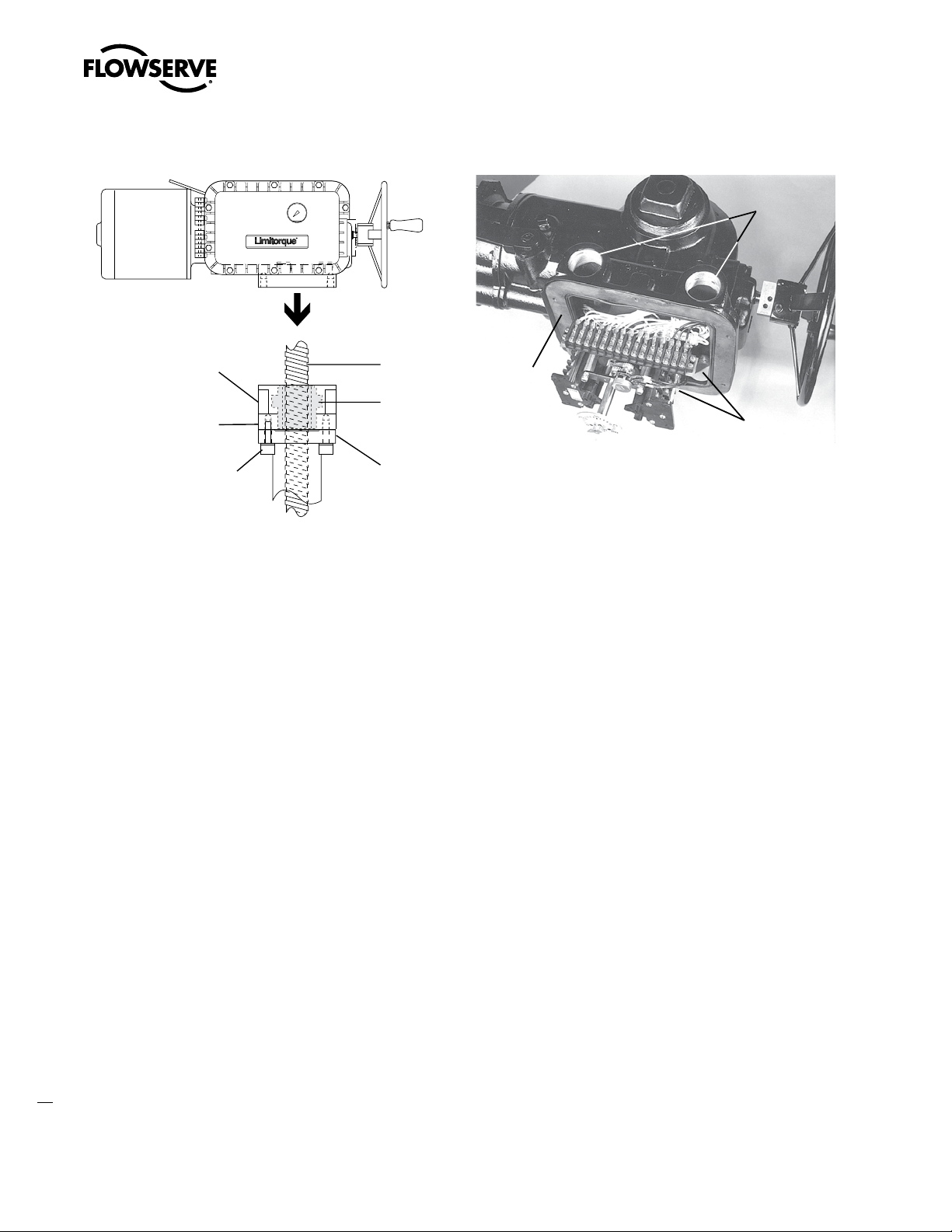
Figure 5: L120-85 Thrust Base Assembly orientation (Drive 2)
Drive 2 Actuator
Mounting Base
Actuator
Mounting
Adapter
Threaded
Valve Stem
#101 Thrust Base
(Drive Sleeve)
Thrust Base
Assembly
#110 Socket Head
Cap Screws
#111 Lockwashers
4.4 Verifying Motor Rotation
Direction
4.4.1 Initial Electrical Connections
c
WARNING: Hazardous Voltage. No electrical power should
be connected until all wiring and Limit Switch adjust-
ments have been completed. Once power is supplied to
unit, exercise caution if cover is not installed.
1. Open the Electrical Compartment Cover (piece 200-1) and
remove the Conduit Pipe Plugs from the opening(s) most conve-
niently located for your power leads and other cabling.
Figure 6: Electrical Compartment and Conduit Pipe Plug openings
Conduit Pipe
Plug Locations
Conduit Pipe
Plug Locations
Electrical
Compartment
2. Adjust the Limit Switches, MDPI (Mechanical Dial Position
Indicator) and Potentiometer following the procedures outlined
in Sections 4.5 and 4.7.
3. Ensure Torque Switch is set properly for your application. In
most cases, adjustments are not needed, but if changes are
required, see Section 4.6, “Torque Switch Settings and Wiring”.
4. Connect wiring to Terminal Strips provided on the actuator.
Refer to the wiring diagram supplied with your specific actuator.
“Fork-type” terminal connections are recommended.
5. Be sure any unused conduit entrances are plugged with metal
Conduit Pipe Plugs.
Notes:
a) Explosion-proof actuators require approved “sealing fittings”
installed in accordance with the National Electric Code.
b) Submersible actuators require approved “sealing fittings” in
order to prevent water entering the actuator.
6. Attach grounding wire to Grounding Lug (piece 14).
Limitorque L120-85 Installation, Operation and Maintenance FCD LMENIM1202-00 – 11/05
14

Figure 7: Grounding Lug location
Grounding Lug
7. Inspect actuator for proper lubrication. Refer to “Lubrication”
Section 6.1 for lubrication instructions.
8. Verify that Motor rotation is operating in the proper direction; the
Motor rotation will have a direct impact on the Limit Switch and
Torque Switch functions. Follow the procedure “Verifying Motor
Rotation Direction” in Sections 4.4.2, 4.4.3 and 4.4.4).
9. Close Electrical Compartment Cover (piece 200-1).
10. Unit is now ready for electrical operation. Continue to “Electrical
Start-up Procedure” in Section 5.3.
4.4.2 Motor rotation (phasing) and OPEN/
CLOSE pushbutton operation.
It is very important to check for correct motor rotation to ensure that
serious damage to your valve or other equipment does not occur.
If the actuator motor rotates in the wrong direction, damage could
occur by over-torquing equipment into a seated position.
Prior to being shipped from the factory, each actuator is inspected to
verify proper operation of the Torque and position Limit Switch and
to ensure that they function correctly (i.e. closes when the CLOSE
pushbutton is depressed, opens with the OPEN pushbutton, etc.).
These inspections are made with a properly phased power source
connected as described in the actuator manual.
a
CAUTION: To ensure proper operation and to prevent your
actuator or other actuated equipment from damage, verify
that your unit is properly connected to its power source.
NOTE: Your application may vary from the following standard wiring
configurations for Three-phase, Single-phase and DC motors. Refer
to your actuator wiring diagram for user-specific wiring configuration.
4.4.3 Three-Phase Motor
1. Using the Handwheel, move the valve to a midtravel position
(midtravel position allows electrical operation in the valve “safe”
area and keeps the OPEN and CLOSED Limit Switches from trip-
ping while testing motor direction).
2. Be prepared to immediately remove power should the actuator
run the wrong way.
3. Test motor direction by momentarily pressing the OPEN push
-
button:
A) If the actuator moves toward CLOSED, immediately turn all
power OFF and reverse the motor leads T1 and T3.
NOTE: Refer to your actuator wiring diagram for user-spe-
cific wiring configuration.
B) If the actuator moves toward OPEN, the motor is wired
properly for the application.
4.4.4 DC Motor
1. Using the Handwheel, move the valve to a midtravel position
(midtravel position allows electrical operation in the valve “safe”
area and keeps the OPEN and CLOSED limit switches from trip-
ping while testing motor direction).
2. Test motor direction by momentarily pressing the OPEN push
-
button:
A) If the actuator moves toward CLOSED, immediately turn all
power OFF and reverse the motor leads A1 and A2.
NOTE: Refer to your actuator wiring diagram for user spe-
cific wiring configuration.
B) If the actuator moves toward OPEN, the motor is wired
properly for the application.
4.5 Limit Switch Settings
The standard L120-85 Limit Switch has 16 contacts. The OPEN/
CLOSE Limit Switch (first eight contacts) has two Rotor Sets, one
for the OPEN position and one for the CLOSED position. Each Rotor
Set has four electrical contacts which can be arranged in any com-
bination of normally OPEN and normally CLOSED. The SPARE Limit
Switch (second eight contacts) has two additional Rotor Sets with
four contacts each that can be set to operate anywhere between the
OPEN and CLOSE positions. These can be used to stop the valve in
mid-travel or to interlock with other equipment such as pumps, fans,
mixers, etc. Refer to Figure 8.
15
Limitorque L120-85 Installation, Operation and Maintenance FCD LMENIM1202-00 – 11/05
flowserve.com
 Loading...