


Repair
Instructions
ISC2
Single pusher seal
Experience In Motion
1 \ Nomenclature
|
|
Part |
Sizes |
ISC2-PX |
marking |
≤ 2.750 inch |
316 SS |
sample |
|
1.875 |
|
(70 mm) |
|
|
1 18 11 13.1 13 16 24 111 103 57 40 |
||||||||||
19 |
5 |
183 |
76 |
15 |
14 |
100 |
5 |
13 |
57.1 |
58 |
Sizes |
|
\ |
|
|
|
|
|
|
|
|
> 2.750 inch |
|
|
|
|
|
|
|
|
||
(70 mm) |
|
|
|
|
|
|
|
|
|
|
|
|
|
|
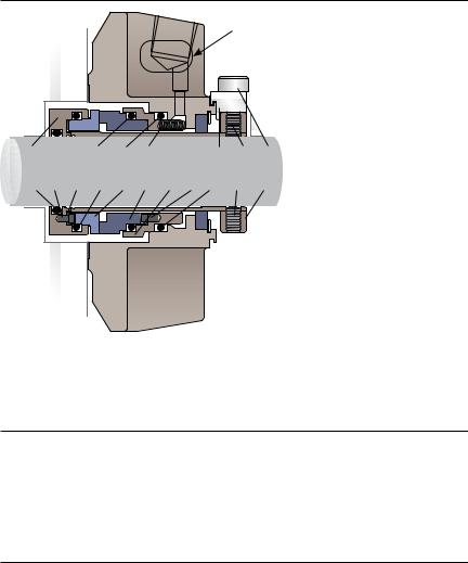
Figure 1 |
|
|
|
|
||
\ Part |
Description |
\Ref.
\1 Sleeve Assembly
\5 Square-headed Pin
\ 11 |
Gland |
\13 Seat Gasket O-ring
\13.1 Seat Gasket O-ring
\14 Stationary Face
\15 Rotating Face
\ 16 |
Springs |
\18 Gland Gasket
\19 Sleeve Gasket O-ring
\24 Gland Bushing
\40 Cap Screw
\57 Cup-point Set Screw
\57.1 Quarter-dog Set Screw
\58 Drive Collar
\76 Rotating Face Gasket O-ring
\100 Stationary Face Support
\103 Setting Device
\111 Snap Ring\
\183 Vibration Dampener
Part references in this document are denoted in square parenthesis, e.g. [15] Primary seal O-rings [13], [13.1] and [76] are the same size and cross-section. \
2\ Disassembly
When disassembling the seal, inspect for conditions which may have caused the seal to be removed from service. If seal was removed due to premature failure, determine what conditions caused that failure and correct any problems prior to returning the repaired seal to service. For assistance with seal failure analysis, please contact your Flowserve representative.
3 Repair or Replace Guide
Seal parts that are always replaced |
\ |
|
• |
Stationary face [14] |
\ |
• |
Rotating face [15] |
\ |
•Springs [16]
•Square-headed pin [5]
•Stationary face support [100]
•All gaskets (O-rings) [13], [13.1], [19] and [76]
• |
Gland gasket [18] |
\ |
• |
Vibration dampener [183] |
\ |
• Setting devices [103] and cap screws [40] |
\ |
|
•Cup-point [57] and quarter-dog set screws [57.1]
•Gland bushing [24] and snap ring [111]
2
\Seal parts that are reconditionable
\ |
• |
Gland assembly [11] |
\ |
|
• |
Sleeve assembly [1] |
\ |
|
• |
Sleeve collar [58] |
|
4\ Inspection and Reconditioning
There are certain critical areas of each part where special attention should be paid to the condition. If any of the listed areas show signs of wear, corrosion, or other defects that cannot be removed without affecting the dimensional size of the surfaces by more than 0.001 - 0.002 inch (0.025 - 0.05 mm), then the
respective part should be replaced. If grit blasting is performed, polish the O-ring surfaces to achieve the required surface finish (see critical area listings for finish requirements). If any parts require machining to correct damage, please contact
your Flowserve representative for dimensional requirements, or for any other |
|
|
questions regarding repair. |
C |
|
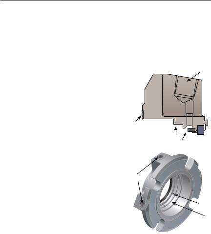
4.1\ Gland assembly [11] see Figures 2 and 3. |
||
|
||
\ A\ Dynamic O-ring surface - Inspect for wear, |
|
|
fretting, nicks, scratches or corrosion. |
|
|
Required surface finish: 32 RMS |
|
\B\ Gasket surface - Remove the old gasket and clean the gasket surface. Inspect for nicks, scratches or corrosion.
\C\ Pipe taps and lifting holes - Inspect for damaged threads or corrosion. Re-tap as necessary.
\D \Anti-rotation pins - Inspect for wear or corrosion. Replace as necessary.
4.2\ Sleeve assembly [1] see Figures 4 and 5.
\A\ O-ring surfaces - Inspect for wear, nicks, scratches, or corrosion. Required surface finish: 63 RMS.
\B \Drive flats or drive pin - Inspect for wear or corrosion. Replace pin as necessary.
\C\ Drive end roundness - No greater than
0.001 inch (0.025 mm) TIR (Total Indicated Reading) under the bushing.
\D\ Inspect ID of sleeve at weld point for corrosion.
B
Figure 2 |
A D |
|
C
 B
B
D
A
Figure 3
3
 Loading...