


|
USER INSTRUCTIONS |
Limitorque HBC Series |
Installation |
FCD LMENIM3501-02-AQ (10/14) |
Operation |
|
Maintenance |
|
|
Experience In Motion

Limitorque HBC Series FCD LMENIM3501-02-AQ – 10/14
Contents
1 |
Introduction |
3 |
|
|
1.1 |
Purpose |
3 |
|
1.2 |
User Safety |
3 |
2 |
Inspection, Installation, and Mounting Procedures |
4 |
|
|
2.1 |
Initial Inspection and Storage Instructions |
5 |
|
2.2 |
Inspection and Recording |
5 |
|
2.3 |
Storage Procedure |
5 |
|
2.4 |
General Mounting Instructions |
6 |
|
2.5 |
Setting Position Limit Stops for HBC-0 through -3 |
6 |
|
2.6 |
Setting Position Limit Stops for HBC-4 through -7 |
7 |
|
2.7 |
HBC Angular Displacement Tolerances |
8 |
3 |
Lubrication |
9 |
|
4 |
Dissassembly and Reassembly Instructions |
11 |
|
|
4.1 |
Safety Precautions |
11 |
|
4.2 |
Safety Practices |
12 |
|
4.3 |
HBC-0 through -3 |
12 |
|
4.4 |
HBC-4 through -7 |
13 |
|
4.5 |
Spur Gear Attachments |
15 |
5 |
Setting Instructions for AWWA Input Shaft Stop |
18 |
|
6 |
How to Order Parts |
23 |
|
Figures
|
Figure 2.1 – HBC-0 through -3 exploded view |
4 |
||
|
Figure 2.2 – HBC nameplate |
5 |
||
|
Figure 2.3 – Hex nut type stop (HBC-0 through -3) |
7 |
||
|
Figure 2.4 – Top of drive sleeve showing available rotation |
8 |
||
|
Figure 4.1 – HBC-0 through -3 assembly |
12 |
||
|
Figure 4.2 |
– HBC-4 through -7 assembly |
14 |
|
|
Figure 4.3 |
– Spur gear attachments |
16–17 |
|
|
Figure 5.1 |
– AWWA input shaft stop (back view) |
20 |
|
|
Figure 5.2 |
– AWWA input shaft stop (complete view) |
21 |
|
|
Tables |
|
||
|
Table 2.1 – HBC angular displacement tolerance |
8 |
||
|
Table 3.1 – Lubricant weights |
10 |
||
2 |
Table 4.1 |
– HBC-0 through -3 parts list |
13 |
|
Table 4.2 |
– HBC-4 through -7 parts list |
14 |
||
|
Table 4.3 |
– HBC-1 through -7 spur gear attachments parts list |
17 |
|
|
Table 5.1 |
– AWWA input shaft stop parts list |
22 |
|

Limitorque HBC Series FCD LMENIM3501-02-AQ – 10/14
1 Introduction
1.1 Purpose
This installation, operation and maintenance manual (IOM) explains how to install and maintain the Flowserve Limitorque HBC gearbox. Information on installation, disassembly, reassembly, lubrication, and spare parts is provided.
1.2 User Safety
Safety notices in this manual detail precautions the user must take to reduce the risk of personal injury and damage to the equipment. The user must read and be familiar with these instructions before attempting installation, operation, or maintenance. Failure to observe these precautions could result in serious bodily injury, damage to the equipment, voiding of the warranty, or operational difficulty.
Safety notices are presented in this manual in three forms:
c |
WARNING: Refers to personal safety. Alerts the user to potential danger. Failure to follow warning notices could |
|
result in personal injury or death. |
aCAUTION: Directs the user’s attention to general precautions that, if not followed, could result in personal injury and/or equipment damage.
NOTE: Highlights information critical to the user’s understanding of the HBC gearbox’s installation and operation.
3
flowserve.com
Limitorque HBC Series FCD LMENIM3501-02-AQ – 10/14
2 |
Inspection, Installation, |
|
|
|
and Mounting Procedures |
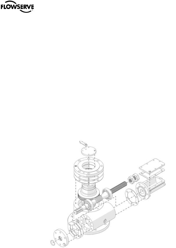
Figure 2.1 – HBC-0 through -3 exploded view
4 |
c |
WARNING: Do not manually operate the HBC gearbox with devices other than the installed handwheel or wrench |
|
|
nut. Using additive force devices (cheater bars, wheel wrenches, pipe wrenches, or other devices of this nature) on |
the gearbox handwheel or wrench nut may cause serious personal injury and/or damage to the gearbox or valve.

Limitorque HBC Series FCD LMENIM3501-02-AQ – 10/14
2.1 Initial Inspection and Storage Instructions
c WARNING: Read this installation, operation and maintenance manual completely before attempting to store the gearbox. If an electric actuator is attached to the HBC gearbox, be aware of the electrical hazards. Consult the actuator installation, operation and maintenance manual for guidance.
2.2 Inspection and Recording
Upon receipt of the gearbox, inspect the condition of the equipment, and record nameplate information.
1.Carefully remove the gearbox from shipping carton or skid. Thoroughly examine the equipment for any physical damage that may have occurred during shipment. If damaged, immediately report the damage to the transport company.
2.A nameplate is attached to each gearbox with the following information:
•Gearbox size
•Order number
•Customer tagging
•Gearbox serial number
•Lubricant type
Record this information for future reference, i.e., ordering parts, or obtaining further information.
Figure 2.2 – HBC nameplate
2.3 Storage Procedure
NOTE: The following is the recommended storage procedure to retain maximum product integrity during storage. Failure to comply with recommended procedure will void the warranty.
Storage (Less Than One Year)
Store gearboxes on wooden skids to protect the machined mounting flange. Place the wooden skids containing the |
|
gearboxes in a clean, dry, protected warehouse. If the gearboxes must be stored outside, they must be covered in |
|
polyethylene protection with silica gel crystals to absorb moisture. If an electric actuator is attached to the HBC, refer |
|
to the storage procedures in its respective manual for appropriate storage procedures. Rotate input shafts every |
5 |
three months to mix the lubricant. |
flowserve.com

Limitorque HBC Series FCD LMENIM3501-02-AQ – 10/14
2.4 General Mounting Instructions
aCAUTION: To avoid disengaging the worm gear segment, ensure that the index mark on the drive sleeve (centerline of gear segment) is oriented to the midpoint of the 90° valve travel. Full stroke rotation of this index mark should not move past the corresponding travel limit index marks on the housing cover. Should the housing cover index marks not be visible, the two housing cover bolts (“C” and “D”) can be used for this alignment. Refer to Figure 2.3.
1.Place the valve in full closed position.
2.Press the splined adapter on valve shaft and insert key (should be a press fit to avoid splined adapter movement in HBC drive sleeve), or utilize a set screw to eliminate movement of splined adapter on the valve shaft.
3.Remove the pointer cap from HBC gearbox.
4.Turn the HBC gearbox input shaft to full closed position. The stops are preset for 90° travel. Be certain of correct direction of rotation.
5.Mount the gearbox on the valve and bolt securely. Be sure of gearbox stop alignment before engaging splines. (See angular displacement tolerances in Table 2.1.)
6.For standard stop setting instructions, see Section 2.5, Setting Position Limit Stops for HBC-0 through -3.
7.For gearboxes with AWWA input shaft stop, see Section 5, Setting Instructions for AWWA Input Shaft Stop.
2.5 Setting Position Limit Stops for HBC-0 through -3
Refer to Figure 2.3.
1.With the valve in full closed position, remove limit stop cover plate.
2.You will note two traveling hex nuts, “A” and “B.”
a.If hex nut “B” is near the position shown, run the hex nut hand-tight against the housing so that one of the flats of the hex nut is on top, facing the cover plate. (If hex nut “A” is near the opposite end of the limit stop housing, proceed with Step 4 first.)
b.If hex nut “A” or “B” hits the housing before the valve was tightly closed, back off the hex nut until the valve is tight and proceed as in Step 2a.
3.Replace the limit stop cover plate and turn the input shaft of the HBC gearbox to fully open the valve.
4.Remove the limit stop cover plate and check the position of hex nut “A.” This nut should be turned until it is flush up against the end of the limit stop housing and one of the flats of the nut is on top facing the limit stop housing cover plate.
5.Bolt the limit stop cover plate into position.
6
Limitorque HBC Series FCD LMENIM3501-02-AQ – 10/14
Figure 2.3 – Hex nut type stop (HBC-0 through -3)
Limit stop housing
Hex nut “A”
Index mark |
|
Two index marks appear |
on drive sleeve |
on housing cover |
|
|
|
|
M |
|
|
l |
|
a |
||
|
|
|
e |
|
ax |
Tr |
v |
|
|
||
Bolt “C” |
Bolt “D” |
Cover plate |
Hex nut “B” |
2.6 Setting Position Limit Stops for HBC-4 through -7
Refer to Figure 4.2.
1.With the valve in the full closed position, remove Stop Screw Cover (piece #16).
2.Remove the Lock Screw (piece #17).
3.Adjust the appropriate Stop Screw (piece #17) based on rotation of the drive sleeve — inward if valve is closed and stop has not yet been reached, or outward if stop has been reached and valve is not yet fully closed.
4.Once the Stop Screw is set, lock securely with Lock Screw.
5.Operate the valve to fully open position and set open stop in the same manner.
7
flowserve.com
Limitorque HBC Series FCD LMENIM3501-02-AQ – 10/14
2.7 HBC Angular Displacement Tolerances
Table 2.1 – HBC angular displacement tolerance
|
|
Angular Displacement |
Splined Tooth |
|
Gearbox Size |
Stop |
|
Gear |
Space in Degrees |
|
|
|
|
|
HBC-0 |
105°1 |
|
170° Gear Segment |
9.00° |
HBC-1 |
114°1 |
|
170° Gear Segment |
6.42° |
HBC-2 |
114°1 |
|
170° Gear Segment |
4.50° |
HBC-3 |
114°1 |
|
170° Gear Segment3 |
3.46° |
HBC-4 |
±7°2 |
|
±7° |
3.00° |
HBC-5 |
±6.75°2 |
|
±6.75° |
2.14° |
HBC-6 |
±9°2 |
|
±9° |
1.80° |
HBC-7 |
±9°2 |
|
±9 |
N/A |
Note 1: Stops used on HBC-0 through HBC-3 incorporate standard hex nuts. The tolerance listed is ±0.31 from basic size on the thickness. The data shown above is based on maximum thickness of both nuts.
Note 2: Displacement is based on 45° travel on either side of gear centerline.
Note 3: Gearboxes with serial numbers less than S/N 365365 have 110° gear segments.
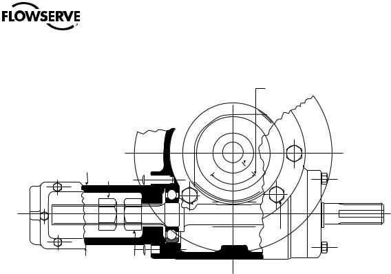
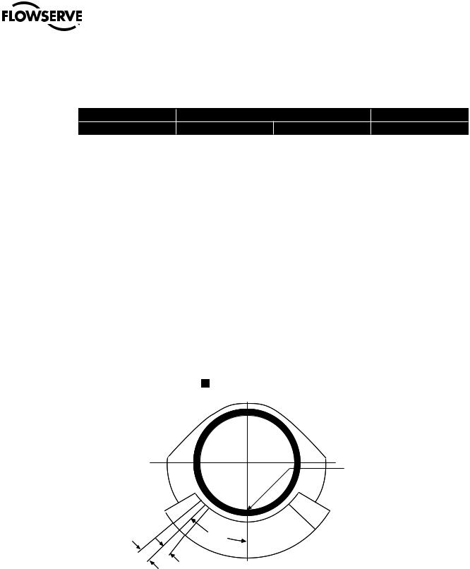
Figure 2.4 – Top of drive sleeve showing available rotation

 Top of drive sleeve with pointer cap removed
Worm gear
Index mark at midpoint of available rotation
Plus |
|
tolerance |
45ϒ |
Minus tolerance
8
 Loading...