


|
USER INSTRUCTIONS |
Limitorque® B320 Series |
Installation |
FCD LMENIM3201-02 – 01/15 |
Operation |
|
Maintenance |
|
|
Experience In Motion

Limitorque B320 Series FCD LMENIM3201-02 – 01/15
This page is left intentionally blank.
2

Limitorque B320 Series FCD LMENIM3201-02 – 01/15
Contents
1 |
Introduction |
|
5 |
|
|
|
|
|
|
|
1.1 |
Purpose |
5 |
|
|
|
|
|
|
|
1.2 |
User Safety |
5 |
|
|
|
|||
2 Product Capabilities and Features |
6 |
|||
|
|
|
|
|
|
2.1 |
Initial Inspection and Storage Instructions |
6 |
|
|
|
|
|
|
|
2.2 |
Product Identification |
7 |
|
|
|
|
|
|
|
2.3 |
Inspection and Recording |
7 |
|
|
|
|
|
|
|
2.4 |
Storage Procedure |
8 |
|
|
|
|
||
3 |
Operator Weights |
9 |
||
|
|
|
||
4 |
Installation Instructions |
10 |
||
|
|
|
|
|
|
4.1 |
Safety Precautions |
10 |
|
|
|
|
|
|
|
4.2 |
Safety Practices |
11 |
|
|
|
|
|
|
|
4.3 |
Installation |
11 |
|
|
|
|
|
|
|
|
4.3.1 |
Installing an Operator with a Threaded Stem Nut |
11 |
|
|
|
|
|
|
|
4.3.2 |
Installing an Operator with a Blank Stem Nut (B320-10 through -90, one-piece) |
11 |
|
|
|
|
|
|
|
4.3.3 |
Installing an Operator with a Blank Stem Nut (B320-90, two-piece) |
12 |
|
|
|
|
|
5 |
Lubrication |
|
13 |
|
|
|
|
|
|
|
5.1 |
Lubrication Inspection |
13 |
|
|
|
|
|
|
|
5.2 |
Factory Lubricant |
13 |
|
|
|
|
|
|
|
5.3 |
Minimum Lubricant Qualities Required |
14 |
|
|
|
|
||
6 |
Disassembly and Reassembly |
15 |
||
|
|
|
||
|
6.1 Disassembly and Reassembly of B320-10 through -80 |
16 |
||
|
|
|
|
|
|
|
6.1.1 |
Disassembly |
16 |
|
|
|
|
|
|
|
6.1.2 |
Reassembly |
16 |
|
|
|
|
|
|
6.2 |
Disassembly and Reassembly of B320-90 |
20 |
|
|
|
|
|
|
|
|
6.2.1 |
Disassembly |
20 |
|
|
|
|
|
|
|
6.2.2 |
Reassembly |
20 |
|
|
|
|
|
|
6.3 |
Disassembly and Reassembly of Spur Gear Attachments |
21 |
|
|
|
|
|
|
|
|
6.3.1 |
Disassembly of 3:1 Spur Gear Attachment for B320-10 through -40 |
21 |
|
|
|
|
|
|
|
6.3.2 |
Reassembly of 3:1 Spur Gear Attachment for B320-10 through -40 |
22 |
|
|
|
|
|
|
|
6.3.3 |
Disassembly of 6.3:1, 10.3:1, and 10.8:1 |
|
|
|
|
Spur Gear Attachments for B320-50, -70, and -80 |
23 |
|
|
|
|
|
|
|
6.3.4 |
Reassembly of 6.3:1, 10.3:1, and 10.8:1 |
|
|
|
|
Spur Gear Attachments for B320-50, -70, and -80 |
23 |
|
|
|
|
|
|
|
6.3.5 |
Disassembly of 5:1 Spur Gear Attachment for B320-90 |
25 |
|
|
|
|
|
|
|
6.3.6 |
Reassembly of 5:1 Spur Gear Attachment for B320-90 |
25 |
|
|
|
|
|
|
|
6.3.7 |
Disassembly of 17.5:1 Spur Gear Attachment for B320-90 |
27 |
|
|
|
|
|
|
|
6.3.8 |
Reassembly of 17.5:1 Spur Gear Attachment for B320-90 |
27 |
|
|
|||
7 How to Order Parts |
30 |
|||
|
|
|
|
|
3
flowserve.com

Limitorque B320 Series FCD LMENIM3201-02 – 01/15
Figures
Figure 2.1 – |
B320 Bevel Gear Operator |
7 |
|
|
|
|
|
Figure 2.2 – |
B320 Nameplate |
8 |
|
|
|
|
|
Figure 6.1 – |
B320-10 and 20 Parts Diagram |
17 |
|
|
|
|
|
Figure 6.2 – |
B320-30 and -40 Parts Diagram |
17 |
|
|
|
|
|
Figure 6.3 – |
B320-50 and -70 Parts Diagram |
18 |
|
|
|
|
|
Figure 6.4 – |
B320-80 Parts Diagram |
18 |
|
|
|
|
|
Figure 6.5 – |
B320-90 Parts Diagram |
20 |
|
|
|
|
|
Figure 6.6 |
– |
3:1 SGA Parts Diagram for B320-10 through -40 |
22 |
|
|
|
|
Figure 6.7 |
– |
6.3:1, 10.3:1, and 10.8:1 SGA Parts Diagram for B320-50 through 80 |
24 |
|
|
|
|
Figure 6.8 |
– 5:1 SGA Parts Diagram for B320-90 |
26 |
|
|
|
|
|
Figure 6.9 |
– 17.5:1 SGA Parts Diagram for B320-90 |
28 |
|
|
|
|
|
Tables
Table 3.1 – Operator Weights |
9 |
|
|
|
|
Table 5.1 – Lubricant Quantities |
14 |
|
|
|
|
Table 6.1 – Quantity of Ball Bearings |
15 |
|
Table 6.2– Common Parts List |
19 |
|
|
|
|
Table 6.3 – B320-90 Parts List |
21 |
|
|
|
|
Table 6.4 |
– 3:1 SGA Parts List for B320-10 through -40 |
23 |
Table 6.5 |
– 6.3:1 , 10.3:1, and 10.8:1 SGA Parts List for B320-50 through 80 |
24 |
|
|
|
Table 6.6 |
– 5:1 SGA Parts List for B320-90 |
26 |
|
|
|
Table 6.7 |
– 17.5:1 SGA Parts List for B320-90 |
29 |
4

Limitorque B320 Series FCD LMENIM3201-02 – 01/15
1 Introduction
1.1 Purpose
This Installation, Operation and Maintenance Manual (IOM) explains how to install and maintain the B320 bevel gear operator. Information on installation, disassembly, lubrication, and spare parts is provided.
1.2 User Safety
Safety notices in this manual detail precautions the user must take to reduce the risk of personal injury and damage to the equipment. The user must read and be familiar with these instructions before attempting installation, operation, or maintenance. Failure to observe these precautions could result in serious bodily injury, damage to the equipment, void of the warranty, or operational difficulty.
Safety notices are presented in this manual in three forms:
cc WARNING: Refers to personal safety. Alerts the user to potential danger. Failure to follow warning notices could result in personal injury or death.
aa CAUTION: Directs the user’s attention to general precautions that, if not followed, could result in personal injury and/or equipment damage.
NOTE: Highlights information critical to the user’s understanding of the gear operator’s installation and operation.
5
flowserve.com

Limitorque B320 Series FCD LMENIM3201-02 – 01/15
2 Productand FeaturesCapabilities
Designed to make operation of multi-turn valves easier The B320 gear operator makes it easier to both manually operate multi-turn valves and convert to a motorized service.
Built for reliable valve control— whether manual or motorized The B320 offers torque ranges up to 8,000 ft-lb (10,856 N m) and thrust capacities to 325,000 lb (1,445 kN) for any application demanding superior strength and accuracy.
Easily adaptable for other applications The B320 is designed to be configured to each customer’s needs:
•Optional handwheel available for manual actuation
•Add a spur gear attachment for greater mechanical advantage
•Couple with an electric actuator from Limitorque for an economical, motorized, multi-turn package
2.1 Initial Inspection and Storage Instructions
cc WARNING: Read this Installation, Operation and Maintenance Manual carefully and completely before attempting to store the gear operator.
6
Limitorque B320 Series FCD LMENIM3201-02 – 01/15
2.2 Product Identification
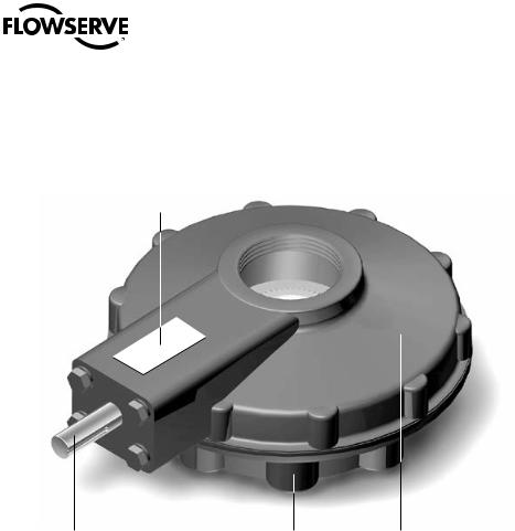
Figure 2.1 – B320 Bevel Gear Operator
Nameplate
Input Shaft |
Mounting Base |
Housing |
2.3 Inspection and Recording
Upon receipt of the gear operator, inspect the condition of the equipment and record nameplate information.
1.Carefully remove gear operator from shipping carton or skid. Thoroughly examine the equipment for any physical damage that may have occurred during shipment. If damaged, immediately report the damage to the transport company.
2.A nameplate is attached to each gear operator with the following information:
•Operator Size
•Limitorque Order Number
•Ratio
•Serial Number
Record this information for future reference, for ordering parts or obtaining further information.
7
flowserve.com

Limitorque B320 Series FCD LMENIM3201-02 – 01/15
Figure 2.2 – B320 Nameplate
2.4 Storage Procedure
NOTE: The following is the recommended storage procedure to retain maximum product integrity during storage. Failure to comply with recommended procedure will void the warranty.
Storage (Less Than One Year)
Operators should be stored in a clean, dry, protected warehouse and should be stored on wooden skids to protect the machined mounting flange. If the operators must be stored outside, they must be covered in polyethylene protection with silica gel crystals to absorb moisture. Input shafts should be rotated every three months to mix lubricant.
8

Limitorque B320 Series FCD LMENIM3201-02 – 01/15
3 Operator Weights
The approximate weights of the gear operators, with and without spur gear attachments, are provided below:
Table 3.1 – Operator Weights
Operator |
|
Without SGA |
|
|
With SGA |
||
|
lb |
|
kg |
|
lb |
|
kg |
B320-10 |
|
|
21 |
|
75 |
|
34 |
45 |
|
|
|
||||
|
|
|
|
|
|
|
|
B320-20 |
51 |
|
23 |
|
80 |
|
36 |
|
|
|
|
|
|
|
|
B320-30 |
57 |
|
26 |
|
86 |
|
39 |
|
|
|
|
|
|
|
|
B320-40 |
68 |
|
31 |
|
97 |
|
44 |
|
|
|
|
|
|
|
|
B320-50 |
143 |
|
65 |
|
198 |
|
90 |
|
|
|
|
|
|
|
|
B320-70 |
254 |
|
115 |
|
309 |
|
140 |
|
|
|
|
|
|
|
|
B320-80 |
418 |
|
190 |
|
474 |
|
215 |
|
|
|
|
|
|
|
|
B320-90 |
745 |
|
339 |
|
875 |
|
398 |
|
|
|
|
|
|
|
|
9
flowserve.com

Limitorque B320 Series FCD LMENIM3201-02 – 01/15
4 Installation Instructions
4.1 Safety Precautions
cc |
WARNING: Read this Installation, Operation and Maintenance Manual carefully and completely |
|
before attempting to install, operate, or troubleshoot the Limitorque operator. |
cc |
WARNING: Potential HIGH PRESSURE vessel — be aware of high-pressure hazards associated |
|
with the attached valve or other actuated device when installing or performing maintenance |
|
on the operator. Do not remove the operator mounting bolts from the valve or actuated device |
|
unless the valve or device stem is secured or there is no pressure in the line. |
cc |
WARNING: For maintenance and/or disassembly of the operator while installed on the valve, |
|
ensure that the operator is not under thrust or torque load. If the valve must be left in service, the |
|
valve stem must be locked in such a way as to prevent any movement of the valve stem. |
cc |
WARNING: Do not manually operate the operator with devices other than the installed hand- |
|
wheel. Using force beyond the ratings of the operator and/or using additive force devices such as |
|
cheater bars, wheel wrenches, pipe wrenches, or other devices on the operator handwheel may |
|
cause serious personal injury and/or damage to the operator and valve. |
cc |
WARNING: Do not exceed any design limitations or make modifications to this equipment |
|
without first consulting Limitorque. |
cc |
WARNING: Use of the product must be suspended any time it fails to operate properly. |
aa |
CAUTION: If a motor actuator is driving the manual operator, do not operate the valve under |
|
motor operation without first checking and setting the limit switch setting and checking for |
|
correct motor rotation. |
aa |
CAUTION: Do not use replacement parts that are not genuine Flowserve Limitorque parts, as |
10 |
serious personal injury and/or damage to the operator and valve may result. |
 Loading...