


Logix Series 1000 Digital Positioner
Installation, Operation and Maintenance Instructions
Flowserve Corporation |
1350 N. Mountain Springs Parkway |
1978 Foreman Dr. |
Flow Control Division |
Springville, Utah 84663-3004 |
Cookville, TN 38501 |
www.flowserve.com |
Phone: 801 489 2233 |
Phone: 931 432 4021 |
Automax Logix Series 1000 Digital Positioner
GENERAL INFORMATION
The following instructions are designed to assist in unpacking, installing and performing maintenance as required on Logix™ Series 1000 Digital Positioners. Series 1000 is the term used for all the positioners contained herein; however, specific numbers indicate features specific to a model (i.e., Logix 1200 indicates that the positioner uses HART® protocol). Product users and maintenance personnel should thoroughly review this bulletin prior to installing, operating, or performing any maintenance on the positioner. For quick calibration instructions, see page 11.
To avoid possible injury to personnel or damage to valve parts, users must strictly adhere to WARNING and CAUTION notes. Modifying this product, substituting non-factory or inferior parts, or using maintenance procedures other than outlined could drastically affect performance and be hazardous to personnel and equipment, and may void existing warranties.
WARNING: Standard industry safety practices must be adhered to when working on this or any other process control product. Specifically, personal protective and lifting devices must be used as warranted.
Logix 1200 Positioner Overview
The Logix 1200 positioner is a two-wire, 4-20 mA input, digital valve positioner which utilizes the HART protocol to allow two-way remote communications with the positioner. The positioner can control both double and single-acting actuators and operates with a signal as low as 3.2 mA. Below 3.2 mA, the operation and communication are suspended (3.2 mA is required
to restart the positioner).
Since the positioner is insensitive to supply pressure changes and can handle supply pressures from 35 to 150 psig, a supply regulator is usually not required; however, an air filter is required due to the close clearances in the spool assembly.
NOTE: The air supply should conform to ISA Standard S7.3 (a dew point at least 18 degrees Fahrenheit (7° C) below ambient temperature, particle size below five microns, and oil content not to exceed one part per million).
Positioner Operation
The Logix 1000 positioner is an electric feedback instrument. Positioning is based on a balance of two signals: one proportional to the command input signal and the other proportional to the valve stem position.
The supply pressure for the positioner pressure modulator is tapped off the main supply and is filtered as it passes through a field-replaceable, coalescing filter element in the module. Next it passes through an internal pressure regulator that regulates it to approximately
22 psig. The air then passes through an orifice that restricts the flow and air consumption.
The pressure modulator further controls the air to 6-12 psig, using a spring-diaphragm flapper that is
attracted by an electromagnet to a nozzle. A temperature compensated hall effect sensor mounted on a circuit board senses the spool valve position. The hall effect sensor and circuitry create an inner feedback loop, which determines how much current to send to the electromagnet for a desired spool valve position. The electromagnet in the feedback loop varies the nozzleflapper spacing, which regulates the output pressure to 6-12 psig, proportional to the digital position algorithm.
When the command and stem position signals are equal, the system will be in equilibrium and the valve stem will be in the position called for by the command signal.
If these opposing signals are not equal, the spool valve will move up (or down) and, by means of the pressure modulator, change the output pressures and flow rate.
This causes the actuator pistons to move until the signal of the position sensor equalizes with the command signal.
FCD AXAIM0064-00 |
(AUTO-64) |
08/04 |
Page: 1 of 16 |
© 2004, Flowserve Corporation, Printed in U.S.A. |
|
||

Logix Series 1000 Digital Positioner
Installation, Operation and Maintenance Instructions
Flowserve Corporation |
1350 N. Mountain Springs Parkway |
1978 Foreman Dr. |
Flow Control Division |
Springville, Utah 84663-3004 |
Cookville, TN 38501 |
www.flowserve.com |
Phone: 801 489 2233 |
Phone: 931 432 4021 |
Table of Contents |
|
General Information ........................................................ |
1 |
Logix 1200 Positioner Overview ...................................... |
1 |
Logix Series Digital Positioner Schematic ...................... |
2 |
Detailed Sequence of Positioner Operations .................... |
3 |
Mounting the Positioner ................................................ |
3 |
Tubing Positioner to Actuator .......................................... |
4 |
Wiring and Grounding Guidelines .................................... |
4 |
Input Cable Shielding................................................ |
4 |
Grounding Screw...................................................... |
4 |
Compliance Voltage .................................................. |
4 |
Cable Requirements ........................................................ |
5 |
Driver Module Assembly.................................................. |
6 |
Spool Valve Cover............................................................ |
7 |
Regulator ........................................................................ |
8 |
Internal Coalescing Filter ................................................ |
8 |
Main PCB Assembly ........................................................ |
9 |
Collector Board .............................................................. |
10 |
Replacing Collector Board ............................................ |
10 |
Field Termination Board ................................................ |
10 |
Stem Position Sensor .................................................... |
10 |
LED Indicators .............................................................. |
11 |
Quick-Cal Button ............................................................ |
11 |
Checking or Setting Internal Regulator Pressure .......... |
13 |
Checking or Setting the Driver Module |
|
Minimum Pressure ................................................ |
13 |
Exploded View of Positioner .......................................... |
14 |
Troubleshooting ............................................................ |
15 |
Spare Parts Kits ............................................................ |
16 |
|
|
|
|
|
Digital Position |
|
|
|
Collector Board |
Algorithm |
|
|
|
|
|
||
|
|
|
Pressure Sensor |
|
|
|
|
Flame Arrestors |
|
|
|
|
Air-to-Open |
|
|
Air Supply |
|
Configuration |
Spool Valve |
|
|
|
|
|
|
Exhaust |
|
|
LED |
|
|
|
|
Display |
|
|
|
|
|
|
|
|
|
OUTOUT 1 |
|
|
|
|
|
OUTOUT 2 |
|
|
Main PCB Tray |
|
|
|
|
|
Ribbon Cable |
|
|
|
|
|
Flame Arrestor |
|
|
Exhaust |
|
|
Filter |
|
|
|
|
|
|
|
|
|
|
|
Regulator |
Steam Position |
|
|
Orifice |
|
|
Sensor |
|
Hall Effect Sensor |
|
|
|
|
|
|
|
||
|
|
Electromagnetic Coil |
Flame |
Flapper |
|
|
|
Nozzle |
Arrestor |
|
|
|
|
|
|
|
|
|
|
Figure 1: Logix 1000 Digital Positioner Schematic |
|
||
FCD AXAIM0064-00 |
(AUTO-64) |
08/04 |
|
|
Page: 2 of 16 |
© 2004, Flowserve Corporation, Printed in U.S.A.

Logix Series 1000 Digital Positioner
Installation, Operation and Maintenance Instructions
Flowserve Corporation |
1350 N. Mountain Springs Parkway |
1978 Foreman Dr. |
Flow Control Division |
Springville, Utah 84663-3004 |
Cookville, TN 38501 |
www.flowserve.com |
Phone: 801 489 2233 |
Phone: 931 432 4021 |
Detailed Sequence of Positioner Operations
An increase in the command signal causes the modulator pressure to increase, pushing the spool assembly upward from its equilibrium position. This opens the spool valve ports, supplying air to Output 1 and exhausting air from Output 2 (Figure 1). This causes the actuator shaft to rotate.
The shaft rotation is transmitted back to the positioner through the stem position feedback linkage, changing proportionally to the valve stem position. The actuator shaft continues to rotate until the stem position signal of the sensor increases sufficiently to counter the signal being sent to the control algorithm. At this point, the spool is at its equilibrium position as the pressures in the cylinder stabilize and the air flow to the actuator decreases. The computer will then make small null adjustments to fine-tune the desired position and compensate for changes in dynamic loading. A decrease in the command signal reverses the described actions.
Mounting the Positioner
CAUTION: Positioner shaft is spring-loaded and features mechanical stops at each end of stroke. Failure to follow these procedures carefully may result in severe damage to positioner. Read through entire procedure before starting.
1.Attach positioner mounting bracket to actuator using fasteners supplied with bracket (Figure 2). Tighten bolts finger-tight only at this time.
2.Install coupler (if required – coupler is not required for NAMUR mounting) on actuator shaft, making sure it is centered.
Figure 3: Actuator Shaft
3.Stroke the actuator to determine direction of rotation as shown in Figure 3. Pay specific attention to the slot that will engage positioner shaft.
4.Carefully grasp positioner shaft with pliers as shown in Figure 4. Turn shaft to determine direction of rotation.
Figure 4: Turn Positioner Shaft
5. Making sure positioner shaft rotation matches actuator shaft rotation, place positioner on mounting bracket (Figure 5). Make sure shafts engage. Do not insert fasteners into positioner at this time.
6. Double-check actuator and positioner rotation. Hold positioner against bracket with fingertips as shown in Figure 6.
Figure 2: Positioner Mounting Bracket
FCD AXAIM0064-00 |
(AUTO-64) |
08/04 |
Page: 3 of 16 |
© 2004, Flowserve Corporation, Printed in U.S.A. |
|
||

Logix Series 1000 Digital Positioner
Installation, Operation and Maintenance Instructions
Flowserve Corporation |
1350 N. Mountain Springs Parkway |
1978 Foreman Dr. |
Flow Control Division |
Springville, Utah 84663-3004 |
Cookville, TN 38501 |
www.flowserve.com |
Phone: 801 489 2233 |
Phone: 931 432 4021 |
WARNING: Keep away from positioner sides, as positioner will suddenly rotate on bracket if not properly aligned and cause injury.
Slowly rotate the actuator. If the positioner shaft is properly aligned, the shaft will rotate freely. If not, the mechanical stops will grab, causing the positioner body to rotate on bracket.
Figure 5: Positioner on Mounting Bracket
7.If the shaft is not properly aligned, repeat steps 3-6. Otherwise, attach positioner to bracket with fasteners included with bracket. Tighten bolts finger-tight only at this time.
8.Stroke actuator/positioner several times to align shafts. Tighten all fasteners.
Tubing Positioner to Actuator
Proper tubing orientation is critical for the positioner to function correctly and have the proper failure mode. Referring to Figure 1, note that for air-to-open valves, the Output 1 port of the positioner manifold, is tubed to the ‘open’ side of the actuator. The Output 2 port of the positioner manifold is tubed to the ‘closed’ side of the actuator. For air-to-close valves the above configuration is reversed.
Wiring and Grounding Guidelines
Input Cable Shielding (Figure 8)
The input loop current signal to the Logix 1200 positioner should be in shielded cable. The shields must be tied to a ground at only one end of the cable to provide a place for environmental electrical noise to be removed from the cable.
In general, shield wire should be connected at the source.
Grounding Screw
The green grounding screw that is located inside the termination cap should be used to provide the unit with an adequate and reliable earth ground reference. This ground should be tied to the same ground as the electrical conduit. Additionally, the electrical conduit should be earth grounded at both ends of its run.
NOTE: The green grounding screw must not be used to terminate signal shield wires.
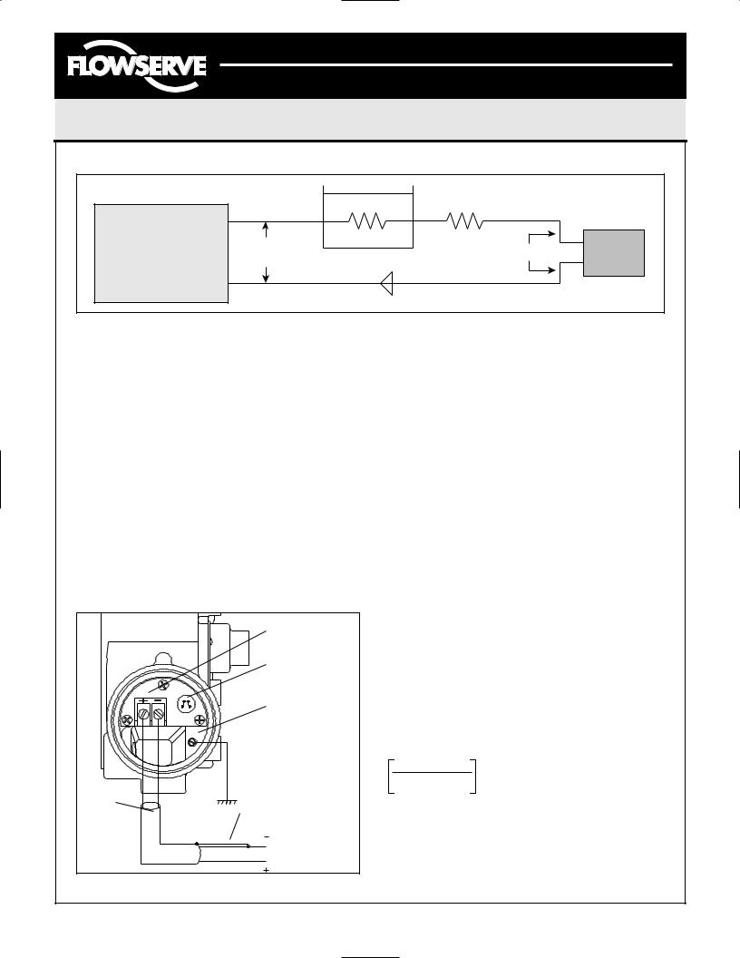
Compliance Voltage (Figure 7)
Output compliance voltage refers to the voltage limit that can be provided by the current source. A current loop system consists of the current source, wiring resistance, barrier resistance (if present), and the Logix Series 1200 impedance. The Logix 1200 positioner requires that the current loop system allow for a 12 VDC drop across the positioner at maximum loop current. The 12 VDC drop across the Logix 1200 positioner terminals is generated by the positioner from the 4-20 mA loop current input.
CAUTION: Never connect a voltage source directly across the positioner terminals. This could cause permanent circuit board damage.
Figure 6: Check Positioner Shaft Alignment
FCD AXAIM0064-00 |
(AUTO-64) |
08/04 |
Page: 4 of 16 |
© 2004, Flowserve Corporation, Printed in U.S.A. |
|
||
Logix Series 1000 Digital Positioner
Installation, Operation and Maintenance Instructions
Flowserve Corporation |
1350 N. Mountain Springs Parkway |
1978 Foreman Dr. |
Flow Control Division |
Springville, Utah 84663-3004 |
Cookville, TN 38501 |
www.flowserve.com |
Phone: 801 489 2233 |
Phone: 931 432 4021 |
|
|
|
|
|
|
|
|
|
R |
R |
|
|
|
Current |
|
|
|
|
|
Logix |
|
|
|
|
|||
Source |
|
|
|
|
1200 |
|
|
|
|
|
|||
|
|
|
|
|
Figure 7: Compliance Voltage
Cable Requirements
The Logix 1200 positioner utilizes the HART Communication protocol. This communication signal is superimposed on the DC 4-20 mA current signal. The two frequencies used by the HART protocol are 1200 Hz and 2200 Hz. In order to prevent distortion of the HART communication, cable capacitance and cable length restrictions must be calculated. The cable length must be limited if the capacitance is too high. Selecting a cable with lower capacitance/foot rating will allow longer cable runs. In addition to the cable capacitance, the network resistance also affects the allowable cable length.
In order to determine if the loop will support the Logix 1200 positioner, perform the following calculation.
Voltage =
Compliance Voltage (@CurrentMAX)
- CurrentMAX*(Rbarrier+Rwire)
Field Terminations
HART Connection
Terminals
Housing EARTH
Terminal
Shielded
Cable Connect Shield at Source
Ground
4-20 mA Current Source
The calculated voltage must be greater than 12 VDC in order to support the Logix 1200 positioner.
Example: DCS Compliance Voltage = 19 VDC
Rbarrier = 300 Ω
Rwire = 25 Ω CURRENTMAX = 20 mA
Voltage = 19 VDC - 0.020 A*(300 Ω + 25 Ω) = 12.5 VDC
The voltage 12.5 VDC is greater than the required 12 VDC; therefore, this system will support the Logix
1200 positioner. The Logix 1200 positioner has an input resistance equivalent to 600 Ω at a 20 mA input current. In order to calculate the maximum network capacitance, use the formula shown in the next column. (NOTE: To control cable resistance, No. 24 AWG cable should be used for runs less than 5000 feet. For cable runs longer than 5000 feet, No. 20 AWG cable should be used.)
Cnetwork (uF) ≤ |
|
|
|
|
|
65 |
|
|
|
- 0.0032 |
||
|
|
|
|
|
|
|
|
|||||
|
|
|
(Rbarrier + Rwire + 390) |
|
|
|
||||||
|
|
|
|
|
|
|
|
|
||||
|
|
|
|
|
|
|
|
|
|
|
||
|
|
|
|
|
|
|
|
|
|
|||
Example: Rbarrier = 300 Ω |
|
|
|
|
|
|
|
|||||
Rwire = 50 Ω |
|
|
|
|
|
|
|
|
||||
Ccable = |
|
|
22 pF |
= |
0.000022 uF |
|
|
|||||
|
|
foot |
|
foot |
|
|
||||||
65
(300 + 50 + 390) - 0.0032 = 0.08 uF= Cnetwork(uF)(Max.)
Max. Cable Length = |
Cnetwork (uF) |
|
|
|
|
Ccable |
|
||
|
|
|
||
Max. Cable Length = |
|
0.08 uF |
= 3636 ft. |
|
|
0.000022 uF/foot |
|||
Figure 8: Field Termination
FCD AXAIM0064-00 |
(AUTO-64) |
08/04 |
Page: 5 of 16 |
© 2004, Flowserve Corporation, Printed in U.S.A. |
|
||
 Loading...