


Installation Instructions
NZ, AU Installation Information
BI452 series |
BI602 series |
|
Built-In Compact |
Built-In Oven |
|
|
Oven |
|
|
|
|
|
|
|
|
|
|
BI602CTE series
Built-In Oven/Cooktop combination
|
|
|
|
|
|
|
|
|
|
|
|
|
|
|
|
|
|
|
|
|
|
|
|
|
|
|
|
|
|
BI602ED series |
BI602XC series |
||||
Built-In Double |
Built-In Oven/ |
||||
|
Oven |
|
Microwave |
||
|
|
|
|
combination |
|
541768C 10.2004 NZ
Warnings and Safety information
 WARNING!
Cut Hazard
Take care - panel edges are sharp.
Failure to use caution could result in minor injury or cuts.
 CAUTION!
In order to avoid hazard these products must be installed according to these instructions.
Please follow installation information carefully. If in doubt consult your local building authority by-laws.
Failure to install the product correctly could invalidate any warranty or liability claims.
The product is to be installed only by an authorised person.
IMPORTANT!
Please make this information available to the person responsible for installing the product as it could reduce your installation costs.
The cavity must be a completely sealed box with no gaps. This will ensure the cooling air flows under the product and through the oven frame to give the correct venting and cooling for the oven and cabinet surround. Failure to seal cavity box may cause distortion of surrounding cabinetry.
Read these instructions carefully before installing or using this product.
Before you start
Ensure a suitable disconnection switch is incorporated in the permanent wiring, mounted and positioned to comply with the local wiring rules and regulations. A means of disconnection with at least a
3mm air gap contact separation in all poles must be incorporated into the fixed wiring in accordance with the wiring rules, unless the local wiring rules allow for the following variation. A means of disconnection from the supply having an air gap separation
in all active (phase) conductors must be incorporated in to the fixed wiring.
Ensure that the location of the oven connection socket is outside the installation space if the product is flush to the rear wall.
Ensure the benchtop and the oven cavity are square and level.
Ensure the electrician provides sufficient free length of mains cable to reach from the
bottom rear of the cavity to at least 1.5 metres in front of the bottom edge of the opening. The cable may enter the cavity from the side, top or bottom, but top entry must be at the rear of the cavity.
Use easy to clean finishes for the wall surfaces surrounding the oven and cooktop to aid
in removal of any cooking fume staining resulting from the use of the oven and cooktop.
Check the height from the floor suits the user.
Ensure that drawers and doors will be clear of obstruction when fully opened.
1
Installation Instructions
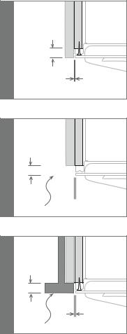
Installation instructions |
Flush fitting installation options |
1 Check that the oven cavity is square and within the limits in the installation dimensions.
2 Remove the mains wiring access cover.
3 Connect the mains wiring and replace the access cover.
4 Remove the oven door and accessories, lift and slide oven into place. When installing the oven it is essential to centre the product in the cavity giving a spacing of 2.5mm from the door edge to the joinery
5 Secure oven in cavity using the four ‘wood screws’ and washers supplied through the enamelled frame at either side of the oven as shown in the flush fitting installation options.
6 Test then refit the door and accessories, check that the oven is firmly secured in the kitchen unit.
a
20 mm
2.5 mm
b
20 mm


 2.5 mm
CUPBOARD FRONT
Installing a cooktop above an oven
If installing a cooktop above the oven ensure adequate clearance is provided for the cooktop as per the Cooktop Manufacturers Instructions.
c
20 mm
2.5 mm
DRAWER FRONT
2
 Loading...