


Fisher & Paykel BGCV21248, BGRV21236, BGRV23030HC, BGCV21230, BGCV21236 Installation manual
...INSTALLATION INSTRUCTIONS
Backguard for Professional Ranges
BGRV2 models
US CA
www.dcsappliances.com
591091A 04.16
1SAFETY AND WARNINGS
!WARNING!
Cut Hazard
Take care - panel edges are sharp.
Failure to use caution could result in injury or cuts.
IMPORTANT SAFETY INSTRUCTIONS!
●Save these instructions for the local inspectors use.
●To avoid hazard, follow these instructions carefully before installing or using this product.
●Please make this information available to the person installing the product - doing so could reduce your installation costs.
●If the installation requires alterations to the domestic electrical system, call a qualified electrician. The electrician should also check that the socket cable section is suitable for the electricity drawn by the range.
●
●
●
●
●
●
●
●
Service should only be done by authorized technicians. Technicians must disconnect the power supply before servicing this appliance.
Installation must comply with your local building and electricity regulations.
Improper installation, adjustment alteration, service or maintenance can cause property damage, injury or death. Read the installation, operating and maintenance instructions thoroughly.
DO NOT obstruct the flow of combustion or ventilation air to the accompanying appliance. Be sure a fresh air supply is available.
California Proposition 65 - The burning of gas cooking fuel generates some by-products which are known by the State of California to cause cancer or reproductive harm. California law requires businesses to warn customers of potential exposure to such substances. To minimize exposure to these substances, always operate this unit according to the manufacturer’s instructions and provide good ventilation to the room when cooking with gas.
Check local building codes for the proper method of installation. Local codes vary. Installation, electrical connections, and grounding must comply with all applicable codes. In the absence of local codes, the range should be installed in accordance with the latest edition of National Fuel Gas Code ANSI Z223.1 and National Electrical Code ANSI / NFPA 70.
Do not place items of interest to children on racks or appliance. Children could be seriously injured if they should climb onto or into the appliance to reach these items.
Do not place combustible material (paper, cloth, plastic, etc.) on the rack.
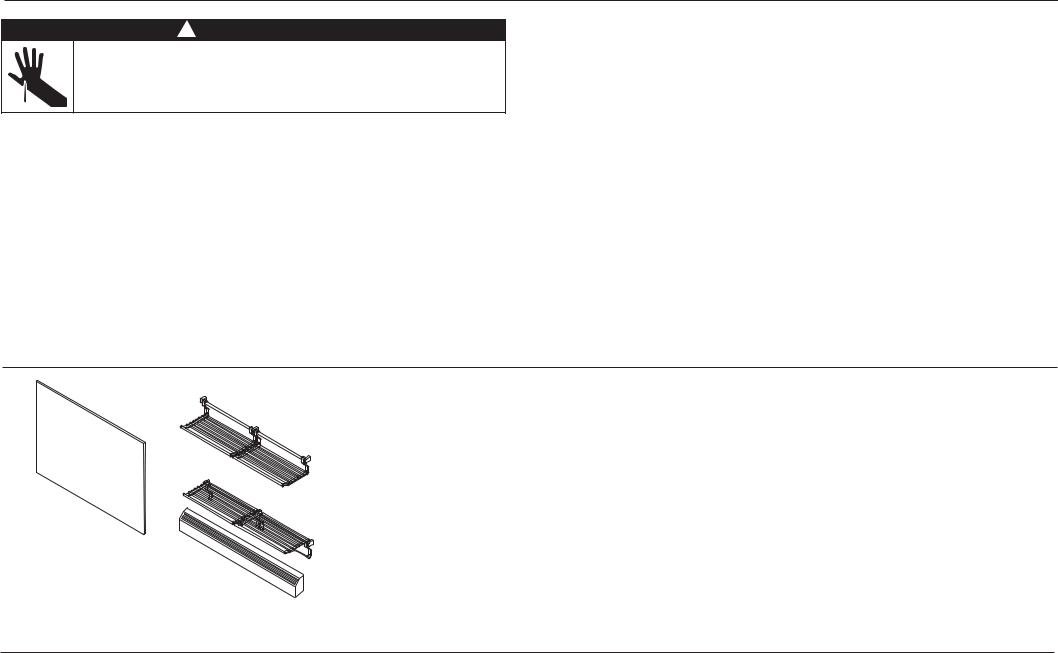
2UNPACKING AND PARTS SUPPLIED
WALL MOUNT HIGH BACKGUARD
LOW SHELF Models
Low Shelf Rack & Handle Kit
30” & 36” Models (x2 Racks)
48” Models (x3 Racks)
Range Backguard |
WALL MOUNT HIGH BACKGUARD |
|
(model specific) (1) |
||
HIGH SHELF Models |
||
|
||
|
High Shelf Rack & Handle Kit |
|
|
30” & 36” Models (x2 Racks) |
|
|
48” Models (x3 Racks) |
|
|
Angled Trim |
●
●
●
Unpacking and handling
Inspect the backguard and racks to verify that there is no shipping damage. If any damage is detected, call the shipper and initiate a damage claim. DCS by Fisher & Paykel is not responsible for shipping damage.
DO NOT discard any packing material (box, pallet, straps) until the unit has been inspected.
Remove the outer carton and any packing material and dispose responsibly.
IMPORTANT!
SAVE THESE INSTRUCTIONS
The models shown in this installation guide may not be available in all markets and are subject to change at any time. For current details about model and specification availability in your country, please go to our website www.dcsappliances.com or contact your local DCS by Fisher & Paykel dealer.
2

3MODEL IDENTIFICATION
RANGE MOUNT LOW BACKGUARD
BGRV2-1230 |
BGRV2-1236 |
BGRV2-1248 |
WALL MOUNT HIGH BACKGUARD LOW SHELF
BGRV2-3030 |
BGRV2-3036 |
BGRV2-3048 |
WALL MOUNT HIGH BACKGUARD HIGH SHELF AND ANGLED VENT TRIM
BGRV2-3030H |
BGRV2-3036H |
BGRV2-3048H |
3
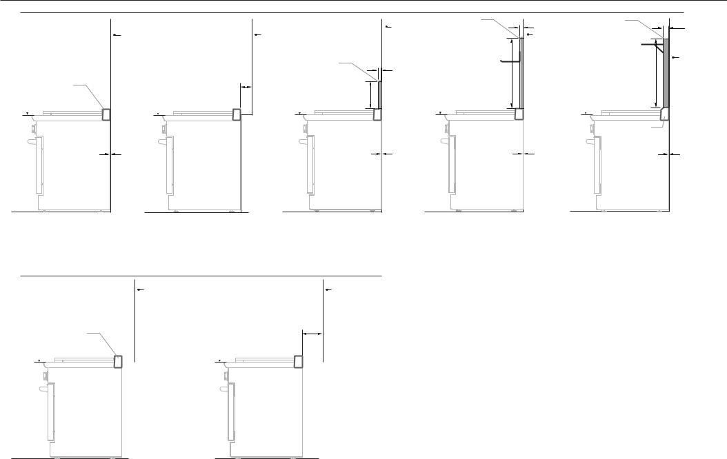
4INSTALLATION SCENARIOS AND USE OF BACKGUARDS
WALL INSTALLATION
Vent Trim |
cooking |
surface |
0” Clearance |
Non-combustible |
surface* |
(required) |
Min. 6” (152mm) |
Clearance |
cooking |
surface |
Combustible |
Surface |
Range Mount |
Low Backguard |
10 3/8” |
(263mm) |
cooking |
surface |
0” Clearance |
Non-combustible |
Wall Mount |
High Backguard |
|
surface* |
Low Shelf |
(required) |
|
1/2” |
|
(13mm) |
28 3/8” |
|
|
|
(720mm) |
cooking |
|
surface |
|
|
0” Clearance |
1/2” |
Wall Mount |
1 5/16” |
|
(13mm) |
(33mm) |
||
High Backguard |
|||
|
|
||
Non-combustible |
High Shelf |
|
|
surface* |
|
|
|
(required) |
|
|
|
|
|
Non-combustible |
|
|
|
surface* |
|
|
26 1/2” |
or |
|
|
Combustible |
||
|
(673mm) |
||
|
surface |
||
|
|
||
cooking |
|
|
|
surface |
|
|
|
|
Angled Vent Trim |
|
|
|
(required) |
|
|
|
0” Clearance |
|
scenario 1 scenario 2 scenario 3 scenario 4 scenario 5
NO BACKGUARD USED |
NO BACKGUARD USED |
RANGE MOUNT LOW BACKGUARD |
WALL MOUNT HIGH BACKGUARD LOW SHELF |
WALL MOUNT HIGH BACKGUARD |
Integral Flat Vent Trim or |
Integral Flat Vent Trim or |
(purchased separately) |
(purchased separately) |
HIGH SHELF AND ANGLED VENT TRIM KIT |
Angled Flat Vent Trim (RGCV2-305 models only) |
Angled Flat Vent Trim (RGCV2-305 models only) |
|
|
(purchased separately) |
(supplied with range) |
(supplied with range) |
|
|
|
ISLAND INSTALLATION
Non-Combustible |
Combustible |
Surface* |
Surface |
|
Min. 6” (152mm) |
|
Clearance |
Vent Trim |
|
cooking |
cooking |
surface |
surface |
scenario 6
NO BACKGUARD USED
Integral Flat Vent Trim or Angled Flat Vent Trim (RGCV2-305 models only)
scenario 7
NO BACKGUARD USED
Integral Flat Vent Trim or Angled Flat Vent Trim (RGCV2-305 models only)
4 |
(supplied with range) |
(supplied with range) |

4INSTALLATION SCENARIOS AND USE OF BACKGUARDS
Important notes
●All ranges come fitted standard with with either an Integral Flat Vent Trim or an Angled Vent Trim (RGCV2-305 models only)
●There are three different backguards available for purchase:
●Range Mount Low Backguard
●Wall Mount High Backguard with Low Shelf
●Wall Mount High Backguard with High Shelf, also supplied with an Angled Vent Trim.
●For installations against non-combustible* surfaces only, you may install the range without a backguard or choose any of the three backguards.
●For installations close to combustible surfaces (above the cooking surface), without a backguard, there must be a minimum 6” (152mm) clearance (see Scenario 2 or 7 opposite)
●For installations immediately against combustible surfaces (above the cooking surface), you must purchase and fit the Wall Mount High Backguard High Shelf and Angled Vent Trim (see Scenario 5 opposite)
●The cooking surface must sit flush or above the adjacent countertop level.
* Non-combustible surfaces:
as defined in ‘National Fuel Gas Code’ (ANSI Z223.1, Current Edition). Clearances from non-combustible materials are not part of the ANSI Z21.1 scope and are not certified by UL. Clearances of less than 6” (152mm) must be approved by the local codes and/or by the local authority having jurisdiction.
BACKGUARD MODEL NUMBERS
|
|
RANGE |
|
WALL |
|
WALL |
|
|
|
|
|
MOUNT HIGH |
|
MOUNT HIGH |
|
BACKGUARD |
|
RANGE |
|
MOUNT LOW |
|
|
|
|||
|
|
BACKGUARD |
|
BACKGUARD |
|
WIDTH |
||
|
|
BACKGUARD |
|
|
|
|||
|
|
|
LOW SHELF |
|
HIGH SHELF |
|
|
|
|
|
|
|
|
|
|
||
30” models |
|
BGRV2-1230 BGRV2-3030 |
|
BGRV2-3030H |
|
29 7/8” (759mm) |
||
|
|
|
|
|
|
|
|
|
36” models |
|
BGRV2-1236 BGRV2-3036 |
|
BGRV2-3036H |
|
35 7/8” (911mm) |
||
|
|
|
|
|
|
|
|
|
48” models |
|
BGRV2-1248 BGRV2-3048 |
|
BGRV2-3048H |
|
47 7/8” (1216mm) |
||
|
|
|
|
|
|
|
|
|
Note: For more information on Backguard installation, refer to the separate instructions provided with your backguard. Backguard Installation Instructions can also be downloaded from our website, www.dcsappliances.com
5
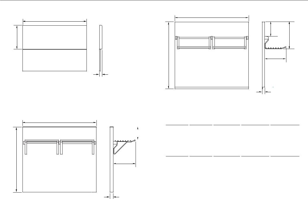
5PRODUCT DIMENSIONS
RANGE MOUNT LOW BACKGUARD |
WALL MOUNT HIGH BACKGUARD LOW SHELF |
|
WIDTH |
WIDTH |
|
|
||
|
5 7/8” |
|
|
(150mm) |
|
10 3/8” |
10 15/16” |
|
(278mm) |
||
(263mm) |
||
|
29 1/8” (740mm)
8 13/16”
(224mm)
1/2”
(13mm)
FRONT
PROFILE |
1/2” |
|
|
|
(13mm) |
FRONT
PROFILE
WALL MOUNT HIGH BACKGUARD HIGH SHELF
WIDTH
|
|
|
|
|
|
RANGE |
|
WALL |
|
WALL |
|
|
|
|
5 3/8” |
|
|
|
|
||||||
|
|
|
|
|
|
|
|
|||||
|
|
SUITABLE |
|
|
MOUNT HIGH |
|
MOUNT HIGH |
|
BACKGUARD |
|||
|
|
|
MOUNT LOW |
|
|
|
||||||
|
|
(136mm) |
RANGE |
|
|
BACKGUARD |
|
BACKGUARD |
|
WIDTH |
||
|
|
|
BACKGUARD |
|
|
|
||||||
|
|
|
|
|
|
|
LOW SHELF |
|
HIGH SHELF |
|
|
|
|
|
|
|
|
|
|
|
|
|
|
|
|
|
|
|
|
|
|
|
|
|
|
|
|
|
|
|
|
|
30” models |
|
BGRV2-1230 BGRV2-3030 |
|
BGRV2-3030H |
|
29 7/8” (759mm) |
||
|
|
|
|
|
|
|
|
|
|
|
|
|
|
|
|
|
36” models |
|
BGRV2-1236 BGRV2-3036 |
|
BGRV2-3036H |
|
35 7/8” (911mm) |
||
|
|
|
|
|
|
|
|
|
|
|
|
|
|
|
|
|
48” models |
|
BGRV2-1248 BGRV2-3048 |
|
BGRV2-3048H |
|
47 7/8” (1216mm) |
||
26 1/2” (673mm)
9 1/16” (230mm)
1 5/16”
(33mm)
FRONT
PROFILE
6
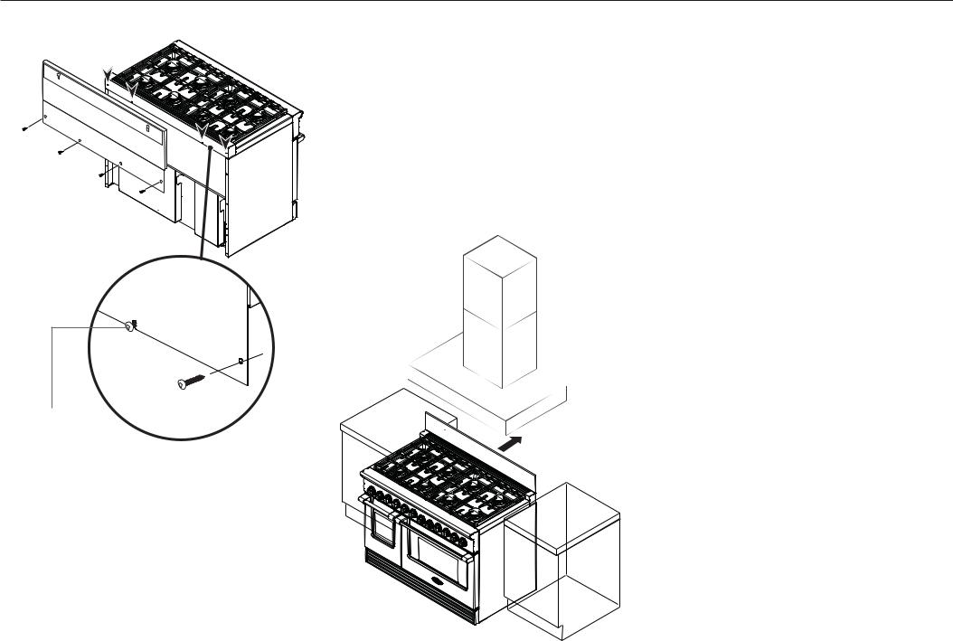
6-A RANGE MOUNT LOW BACKGUARD - ASSEMBLY
1
2
Center screw |
|
These screws |
|
come pre-attached to |
3 |
rear of range |
Attach low backguard to the rear of the range
1Align the backguard with the range, so that it rests on the vent trim.
2Fasten the bottom of the backguard to the rear of the range using all the screws provided, as shown.
The two center screws come already attached to the range for your convenience.
Finally position range
3Push the range into position.
Follow the rest of the instructions shown in the range installation instructions.
7
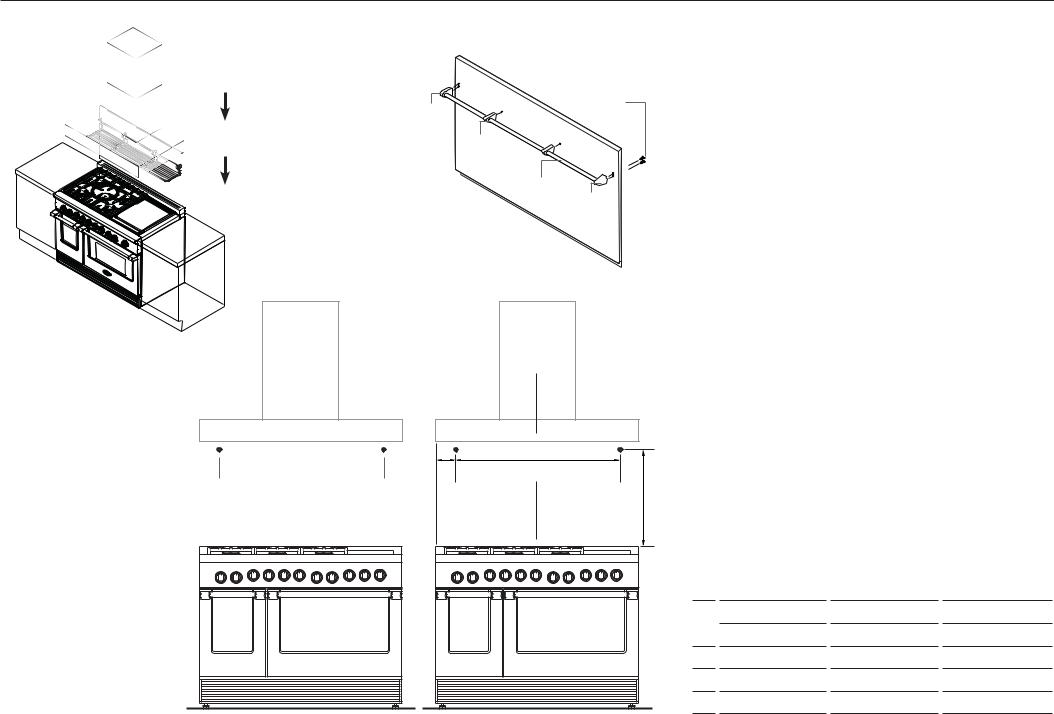
6-B WALL MOUNT HIGH BACKGUARD WITH LOW SHELF - ASSEMBLY
1 |
VENT HOOD |
|
|
#10 machine |
|
|
|
|
|
|
|
End |
|
screws |
|
|
|
|
|
|
|
cap |
|
|
|
BACKGUARD |
|
|
Center |
|
|
|
|
stanchion |
|
|
|
|
Rod |
|
RANGE |
|
3 |
End |
|
|
cap |
||
|
|
|
|
2
1Recommended installation order:
1] VENT HOOD 2] BACKGUARD 3] RANGE
Locate and Mark the two mounting screw locations
2Use the diagram below depending on your particular model.
Attach rod etc
3Attach rod, end caps and center stanchion to backguard with #10 machine screws supplied.
continued over...
|
|
A |
B |
|
|
|
Mounting |
Mounting |
|
|
|
|
|
|
|
|
|
|
||
Hole |
Hole |
|
C |
|
|
|
location |
location |
|
|
|
|
|
|
|
|
Top of Vent Trim |
|
|
|
|
|
|
Mounting screw locations |
|
|
|
|
|
|
|
30” MODELS |
36” MODELS |
48” MODELS |
|
|
|
|
inches (mm) |
inches (mm) |
inches (mm) |
|
|
|
A |
6 15/16” (176) |
1 15/16” (50) |
7 15/16” (202) |
|
|
|
B |
16” (406) |
32” (813) |
32” (813) |
|
|
|
C |
26 9/16” (675) |
26 9/16” (675) |
26 9/16” (675) |
8
 Loading...