


MR850 RESPIRATORY
HUMIDIFIER
Technical Manual
REVISION J
Copyright ©2005 Fisher & Paykel Healthcare Ltd.
Auckland, New Zealand
Fisher & Paykel Healthcare Head |
France/Benelux: |
Office: |
Parc Silic-Bal F, |
PO Box 14-348, Panmure, |
10 Avenue de Quebec, |
Auckland 1134 |
Silic 512 Villebon, 91946, |
New Zealand |
Courtaboeuf, Cedex, France. |
Email: info@fphcare.com |
Tel: +33–(0)1-6446-5201 |
Web Site: www.fphcare.com |
Fax: +33–(0)1-6446-5221 |
Tel: +64-(0)9-574-0100 |
|
Fax: +64-(0)9-574-0158 |
|
Australia: |
USA: |
36-40 New Street, |
Suite 101 22982 Alcalde Drive, |
Ringwood, Victoria 3134, |
Laguna Hills, California 92653, USA |
Australia, |
Tel: +1-(949)-470-3900 |
Tel: +61-(0)3-9879-5022 |
Fax: +1-(949)-470-3933 |
Fax: +61-(0)3-9879-5232 |
Toll Free: (800)-446-3908 |
Germany: |
UK and Ireland(European Authorised Representative): |
Hundsbergerstrasse 45 |
Unit 16, Cordwallis Park |
73642 Welzheim |
Clivemont Road, Maidenhead, SL6 7BU, |
Germany |
United Kingdom |
Tel: +49-(0)7182-93777-0 |
Tel: +44-(0)1628626 136 |
Fax: +49-(0)7182-93777-99 |
Fax: +44-(0)1628626 146 |
2 MR850 Technical Manual * Revision J * Issued November 2005 * Ref. 185041340 (185041713 internal)
TABLE OF CONTENTS
1 |
INTRODUCTION ................................................................................................................................. |
7 |
1.1 |
ABOUT THIS MANUAL.............................................................................................................................. |
7 |
1.2 |
GLOSSARY ............................................................................................................................................ |
7 |
1.3 |
DEFINITIONS .......................................................................................................................................... |
8 |
1.4 |
PRODUCT APPLICATION.......................................................................................................................... |
8 |
2 |
HUMIDIFIER SYMBOLS..................................................................................................................... |
9 |
|
3 |
SPECIFICATIONS............................................................................................................................. |
10 |
|
3.1 |
MECHANICAL ....................................................................................................................................... |
10 |
|
3.2 |
ELECTRICAL......................................................................................................................................... |
10 |
|
3.3 |
TEMPERATURE RANGE ......................................................................................................................... |
10 |
|
|
3.3.1 |
Heater Wire Mode.................................................................................................................. |
10 |
|
3.3.2 Non Heater Wire Mode.......................................................................................................... |
10 |
|
|
3.3.3 |
Alarm Parameters.................................................................................................................. |
10 |
3.4 |
PERFORMANCE .................................................................................................................................... |
11 |
|
3.5 |
TRANSPORT AND STORAGE ENVIRONMENTAL CONDITIONS .................................................................... |
11 |
|
3.6 |
STANDARDS AND APPROVALS............................................................................................................... |
11 |
|
4 |
OPERATING MODES AND CONTROLS......................................................................................... |
12 |
|
4.1 |
HUMIDIFIER OPERATION ....................................................................................................................... |
12 |
|
|
4.1.1 |
Heater wire operation ............................................................................................................ |
12 |
|
4.1.2 |
Non-Heater Wire Operation................................................................................................... |
13 |
|
4.1.3 |
Stand-by Operation................................................................................................................ |
13 |
|
4.1.4 |
Power Up Sequence.............................................................................................................. |
14 |
|
4.1.5 Humidity Compensation (HC) mode...................................................................................... |
14 |
|
|
4.1.6 |
Breathing Circuit Recognition ................................................................................................ |
15 |
4.2 |
HUMIDIFIER CONTROLS ........................................................................................................................ |
16 |
|
|
4.2.1 |
Power Button ......................................................................................................................... |
16 |
|
4.2.2 |
Mode Button .......................................................................................................................... |
16 |
|
4.2.3 |
Mute Button ........................................................................................................................... |
17 |
4.3 |
TEMPERATURE DISPLAY ....................................................................................................................... |
17 |
|
|
4.3.1 Showing Chamber and Airway Temperature ........................................................................ |
17 |
|
4.4 |
SETUP INDICATORS .............................................................................................................................. |
17 |
|
|
4.4.1 |
Heater wire connector ........................................................................................................... |
17 |
|
4.4.2 Temperature / Flow Probe Connector ................................................................................... |
18 |
|
|
4.4.3 Chamber Probe & Airway Probe ........................................................................................... |
18 |
|
|
4.4.4 Chamber or Airway Probe Alarm with Probe connector alarm.............................................. |
18 |
|
|
4.4.5 |
Water Out Indicator................................................................................................................ |
19 |
4.5 |
OPERATIONAL ALARMS......................................................................................................................... |
19 |
|
|
4.5.1 |
Temperature Indicator ........................................................................................................... |
19 |
|
4.5.2 |
Non-Heater Wire Operation................................................................................................... |
20 |
|
4.5.3 |
See Manual Indicator............................................................................................................. |
20 |
5 |
MAINTENANCE PROCEDURES...................................................................................................... |
21 |
|
5.1 |
MAINTENANCE SCHEDULE .................................................................................................................... |
21 |
|
|
5.1.1 |
MR850 Humidifier .................................................................................................................. |
21 |
|
5.1.2 |
MR850 Temperature Probe................................................................................................... |
21 |
5.2 |
SAFETY CHECK.................................................................................................................................... |
22 |
|
5.3 |
CLEANING INSTRUCTIONS..................................................................................................................... |
23 |
|
|
5.3.1 |
MR850 Humidifiers ................................................................................................................ |
23 |
|
5.3.2 |
Temperature Flow Probe....................................................................................................... |
23 |
|
MR850 Technical Manual * Revision J * Issued November 2005 * Ref. 185041340 (185041713 internal) |
3 |
|
6 |
TROUBLESHOOTING ..................................................................................................................... |
24 |
6.1 |
OPERATIONAL PROBLEMS.................................................................................................................... |
24 |
6.2 |
TECHNICAL PROBLEMS ........................................................................................................................ |
26 |
6.3 |
“SEE MANUAL” ERROR CODES............................................................................................................. |
27 |
6.4 |
DIAGNOSTIC MENU.............................................................................................................................. |
29 |
|
6.4.1 Diagnostic Menu for Software Versions 5.45, 5.70............................................................... |
29 |
|
6.4.2 Diagnostic Menu for Software Version 6.00 ......................................................................... |
30 |
|
6.4.3 Diagnostic Menu for Software Version 7.00 & 7.21 .............................................................. |
31 |
|
6.4.4 Diagnostic Menu for Software Version 7.14 & 7.22 .............................................................. |
32 |
|
6.4.5 Diagnostic Menu for Software Version 7.23 ......................................................................... |
34 |
7 |
SERVICING PROCEDURES............................................................................................................ |
35 |
|
7.1 |
GENERAL CONSIDERATIONS ................................................................................................................ |
35 |
|
7.2 |
DISASSEMBLY ..................................................................................................................................... |
35 |
|
|
7.2.1 |
Opening the case.................................................................................................................. |
35 |
|
7.2.2 |
Replacing Fuses ................................................................................................................... |
36 |
|
7.2.3 Replacement of Printed Circuit Boards (PCBs) .................................................................... |
37 |
|
|
7.2.4 |
Replacement of Transformer ................................................................................................ |
38 |
|
7.2.5 Servicing the Heater Plate .................................................................................................... |
38 |
|
|
7.2.6 |
Installing New Software......................................................................................................... |
42 |
|
7.2.7 Replacing the Mains Cable ................................................................................................... |
43 |
|
|
7.2.8 |
Closing the case.................................................................................................................... |
43 |
8 |
PERFORMANCE TESTING ............................................................................................................. |
44 |
|
8.1 |
HUMIDIFIER PERFORMANCE TESTING ................................................................................................... |
44 |
|
|
8.1.1 Entering the Service Menu.................................................................................................... |
44 |
|
|
8.1.2 |
Humidifier Calibration Check ................................................................................................ |
44 |
|
8.1.3 |
Humidifier Display Test ......................................................................................................... |
45 |
|
8.1.4 Humidifier Voltage Calibration Check ................................................................................... |
46 |
|
|
8.1.5 Humidifier Warm-up and Control Check ............................................................................... |
46 |
|
8.2 |
PROBE ACCURACY CHECK................................................................................................................... |
47 |
|
|
8.2.1 Probe Temperature Accuracy Test ....................................................................................... |
47 |
|
|
8.2.2 Probe Flow Accuracy Test .................................................................................................... |
47 |
|
9 |
RECOMMENDED MAINTENANCE CHECKLIST............................................................................ |
49 |
9.1 |
HUMIDIFIER CHECK (ANNUALLY) .......................................................................................................... |
49 |
9.2 |
PROBE CHECK (EVERY SIX MONTHS).................................................................................................... |
49 |
10 |
SPARE PARTS................................................................................................................................. |
51 |
11 |
CALIBRATION PROBE ................................................................................................................... |
55 |
12 |
SERIAL PORT & LOGGING SOFTWARE ...................................................................................... |
56 |
12.1 |
INTRODUCTION............................................................................................................................... |
56 |
12.2 |
INSTALLATION................................................................................................................................. |
56 |
12.3 |
OPERATING INSTRUCTIONS ......................................................................................................... |
56 |
|
12.3.1 Viewing Humidifier Data........................................................................................................ |
56 |
|
12.3.2 Logging Humidifier Data to File............................................................................................. |
57 |
13 |
EMC INFORMATION........................................................................................................................ |
58 |
14 |
PRODUCT CHANGE HISTORY....................................................................................................... |
60 |
4 MR850 Technical Manual * Revision J * Issued November 2005 * Ref. 185041340 (185041713 internal)
Revision |
Description of Technical Manual Change |
Date Issued |
|
A |
First release technical manual. |
12 Jan. 1999 |
|
|
Covers Revision A PCB’s ONLY. |
|
|
B |
Second release technical manual. |
6 May 1999 |
|
|
Covers Revision C and later PCB’s ONLY. |
|
|
C |
Add “View850” Software Instructions |
1 Mar. 2000 |
|
|
|
|
|
D |
Neonatal volume ventilation capability. |
15 May 2001 |
|
|
3.4 Performance |
|
|
|
4.1.2 Power Up sequence. |
|
|
|
4.1.3 Manual Temperature Compensation (TC). |
|
|
|
5.3 Cleaning Instructions |
|
|
|
Appendix E – Product Change History. |
|
|
E |
Covers release of software version 6.00. |
1 November 2001 |
|
|
3.4 Performance |
|
|
|
Recommended Operating Temperature: 15 to 26ºC |
|
|
|
4.1.1 Stand-by. |
|
|
|
Changed stand-by power limits. |
|
|
|
4.1.3 Humidity Compensation (HC) mode. |
|
|
|
Auto HC mode option. |
|
|
|
4.2 Humidifier Controls |
|
|
|
Power button must be held for 1 second to switch OFF. |
|
|
|
4.4 Setup Indicators |
|
|
|
Two LED’s now indicate heater wire connect alarm. |
|
|
|
4.5 Operational Alarms |
|
|
|
Low temperature alarm enabled during stand-by. |
|
|
|
6.4 Diagnostic Menu |
|
|
|
“OFF” Offset removed from diagnostic menu. |
|
|
|
|
|
|
F |
Covers release of software version 7.00. |
2 April 2002 |
|
|
3.4 Performance |
|
|
|
Recommended Operating Temperature: 18 to 26ºC |
|
|
|
4.1.3 Humidity Compensation (HC) mode |
|
|
|
Changed step size to 1 °C in non-invasive mode |
|
|
|
4.1.4 Breathing Circuit Recognition added |
|
|
|
6.3 See – Manual, Error Codes |
|
|
|
removed redundant error code “E33” |
|
|
|
6.4 Diagnostic Menu |
|
|
|
add new functions “CHP” and “Cct” |
|
|
|
|
|
|
G |
Technical manual now covers software versions 5.45, 5.70, 6.00, 7.00 |
1 May 2003 |
|
|
and 7.14 |
|
|
|
The following sections have been modified: 3.3, 4.1.3, 4.1.5, 4.4, 5.3, |
|
|
|
6.4, 7.2.3, 7.2.6, Appendix E |
|
|
|
|
|
|
H |
Added Non-Heater Wire Mode in sections 3.0, 4.0, 6.0, and updated |
1 July 2004 |
|
|
Product Change History |
|
|
I |
8.1.2 Humidifier Calibration Check – Equipment Required |
1 August 2005 |
|
|
Removed the reference to the service kit |
|
|
|
10 Spare Parts |
|
|
|
Added parts 17 to 22. |
|
|
|
12.1 Introduction |
|
|
|
Updated how to get View850 and the serial cable |
|
|
|
12.2 Installation |
|
|
|
Changed View850 installation from floppy disk to CD |
|
|
|
12.3.1 Viewing Humidifier Data |
|
|
|
Updated how to run View850 and how to change the com. Port |
|
|
|
Add section, 13. EMC Information |
|
|
|
|
|
|
MR850 Technical Manual * Revision J * Issued November 2005 * Ref. 185041340 (185041713 internal) |
5 |
||
Revision |
Description of Technical Manual Change |
Date Issued |
|
J |
1.4 |
Product Application, Add warning to connect humidifier only to a |
1 November 2005 |
|
pure sine wave power source |
|
|
|
5.2 |
Safety Check, add CAUTION: and NOTE: |
|
|
6.3 |
“See manual” Error codes, Elaborate the fault description |
|
|
8.1.5 Humidifier Warm-up and Control Check, Change test flow rate |
|
|
|
from 20±10 SLPM to 10±5 SLPM. Reference test limits to airway and |
|
|
|
chamber set temperatures rather than fixed values. |
|
|
|
8.2.2 Probe Flow Accuracy Test, Change test flow rate from 20±2 |
|
|
|
SLPM to 10±1 SLPM. Check flow measurement is now between 5 and |
|
|
|
15 LPM |
|
|
|
10 Spare Parts, add items 23,24,25,26 |
|
|
Note:
1.Fisher & Paykel Healthcare have a policy of continued product improvement and reserve the right to change specifications without notice.
2.This Technical Manual covers software version 5.45, 5.70, 6.00, 7.00, 7.14, 7.21, 7.22, 7.23 and PCB Revision C, D and E. Refer to previous revisions of the Technical Manual for earlier software and PCB versions.
6 MR850 Technical Manual * Revision J * Issued November 2005 * Ref. 185041340 (185041713 internal)
Introduction
1.1About this Manual
This manual is intended for qualified service personnel who will perform maintenance and servicing on the Fisher & Paykel Healthcare MR850 Respiratory Humidifier. This manual covers the product specifications, includes a maintenance schedule, and provides the necessary information required for servicing.
NOTE: Some software may not be available in your country. Refer to your local Fisher & Paykel Healthcare representative for the appropriate software version. Maintenance procedures should be carried out at regular intervals (as recommended in the maintenance schedule), to ensure that the humidifier and its accessories are working correctly.
If a fault should occur with the humidifier, follow the troubleshooting guide (section 6) in order to find the most likely cause. If the unit requires servicing, make sure the servicing procedures are followed in order to prevent damage to the humidifier. After service, or as part of the maintenance schedule, a humidifier performance check should be completed.
Due to the nature of the electronics contained within this humidifier, it is not recommended that the printed circuit boards be serviced at component level. Instead, if the PCBs are found to be malfunctioning, they should be replaced.
1.2 |
Glossary |
|
|
Chamber |
Device that allows gas to be to be heated and humidified by passing it |
||
|
|
over heated water. |
|
Temperature / Flow |
Sensor assembly for measuring temperature and flow of respiratory |
|
|
Probe |
|
gases traveling through the breathing circuit. Consists of a chamber |
|
|
|
and airway probe. |
|
Airway Probe |
Sensor assembly for measuring gas temperature at the end of the |
|
|
|
|
inspiratory limb. |
|
Chamber Probe |
Sensor assembly for measuring gas flow and temperature at the |
|
|
|
|
outlet of the humidification chamber. |
|
Thermistor |
A temperature sensitive resistor placed inside the chamber and |
|
|
|
|
airway probes. |
|
Chamber Set Point |
The temperature that the humidifier attempts to maintain at the |
|
|
|
|
chamber probe port. |
|
Airway Set Point |
The temperature that the humidifier attempts to maintain at the airway |
||
|
|
probe port. |
|
Heater Wire Adaptor |
Electrical connector between the breathing circuit and the humidifier. |
|
|
Breathing Circuit |
Tubing that carries respiratory gases to and from the patient. |
|
|
Dual Heated Breathing |
A breathing circuit that is heated by means of heater wires, in both the |
||
Circuit |
|
expiratory and inspiratory limbs. |
|
Single Heated |
A breathing circuit that is heated by means of a heater wire, in only |
|
|
Breathing Circuit |
the inspiratory limb. |
|
|
PCB |
|
Printed Circuit Board. |
|
Heater Wire |
Wire inside the breathing circuit which heats the respiratory gases. |
|
|
Inspiratory Limb |
The section of the breathing circuit that takes the inspired gases to |
|
|
|
|
the patient. |
|
|
MR850 Technical Manual * Revision J * Issued November 2005 * Ref. 185041340 (185041713 internal) |
7 |
|

Expiratory Limb |
The section of the breathing circuit that takes the expired gases from |
|
the patient. |
1.3Definitions
NOTE: A NOTE provides important information or explanation of procedures or conditions which may otherwise be misinterpreted or overlooked.
CAUTION: A CAUTION statement designates the possibility of damage to this or other equipment if a procedure is not followed exactly.
WARNING:
A WARNING statement refers to conditions with a possibility of personal injury if a procedure is not followed exactly.
1.4Product Application
The MR850 is a respiratory humidifier designed for use in hospital intensive care units. It is used to provide optimum humidity to respiratory gases delivered to patients via endotracheal tubes or face masks.
Refer to the Respiratory Humidification Product Catalogue or your local Fisher & Paykel Healthcare representative for a list of approved accessories.
WARNING:
•The use of breathing circuits, chambers or other accessories which are not approved by Fisher & Paykel Healthcare may impair performance or compromise safety.
•Ensure that Invasive mode is set for patients that have bypassed airways.
•Ensure maintenance of grounding integrity by connection to a "hospital grade" receptacle.
•Always disconnect supply before servicing.
•When mounting a humidifier adjacent to a patient ensure that the humidifier is always securely mounted and positioned lower than the patient.
•The operation of high frequency surgical apparatus, shortwave or microwave equipment in the vicinity of the humidifier may adversely affect its function. If this occurs, the humidifier should be removed from the vicinity of such devices.
•Ensure that both temperature probe sensors are correctly and securely fitted. Failure to do so may result in gas temperatures in excess of 41 °C being delivered to the patient.
•Do not touch the glass tip of the chamber temperature probe during use. Keep black connectors dry at all times.
•Visually inspect accessories for damage before use.
•Normal operation can not be guaranteed if powered from a source other than a pure sine wave, such as a square wave inverter.
8 MR850 Technical Manual * Revision J * Issued November 2005 * Ref. 185041340 (185041713 internal)
2 |
|
Humidifier Symbols |
|
|
|
||||||
|
|
|
|
|
|
|
Caution: Hot surfaces may |
|
|
Power On/Off (stand by) |
|
|
|
|
|
|
|||||||
|
|
|
|
|
|
|
exceed 85 °C |
|
|
|
|
|
|
|
|
|
|
|
Type BF |
|
|
Invasive Mode |
|
|
|
|
|
|
|
|
|
|
|||
|
|
|
|
|
|
|
|
|
|||
|
|
|
|
|
|
||||||
|
|
|
|
|
|
|
Attention – consult |
|
|
Non-invasive mode |
|
|
|
|
|
|
|
|
|
|
|||
|
|
|
|
|
|
|
|||||
|
|
|
|
|
|
|
accompanying documents |
|
|
|
|
|
|
|
|
|
|
|
Alternating Current |
|
|
Temperature Alarm |
|
|
|
|
|
|
|
|
|
|
|||
|
|
|
|
|
|
|
Drip proof protection to IPX1 |
|
|
Serial Port |
|
|
|
|
|
|
|
|
|||||
|
|
|
|
|
|
|
Date of manufacture |
|
|
Protective Earth |
|
|
|
|
|
|
|
|
|
|
|||
|
|
|
|
|
|
|
|||||
|
|
|
|
|
|
|
|
|
|||
|
Year-month |
|
|
|
|||||||
|
|
|
|
|
|
|
C-tick for EMC |
|
|
|
Caution: Electrostatic |
|
|
|
|
|
|
|
|
|
|
||
|
|
|
|
|
|
|
|
|
|
|
Sensitive Device |
|
|
|
|
|
|
|
|
|
|
|
|
|
|
|
|
|
|
|
|
|
|
|
|
Do not discard
WEEE collection (EU only)
MR850 Technical Manual * Revision J * Issued November 2005 * Ref. 185041340 (185041713 internal) |
9 |
3 Specifications
3.1Mechanical
Dimensions: |
140 mm x 173 x 135 (without chamber fitted) |
Weight: |
2.8 kg (without chamber fitted) |
|
Approx. 3.1 kg (with chamber fitted, and filled with water) |
3.2 |
Electrical |
|
|
|
|
|
|
|
|
|
|
MR850 Model Number |
|
Supply Voltage |
|
Supply Current |
|
MR850Axx |
|
230 V~ |
|
1.0 A Max |
|
MR850Pxx |
|
127 V~ |
|
1.8 A Max |
|
MR850Jxx |
|
115 V~ |
|
2.0 A Max |
|
MR850Gxx |
|
100 V~ |
|
2.4 A Max |
|
Supply Frequency: |
50 or 60 Hz, Sine Wave |
|
|||
Heater Plate Capacity |
150 W at nominal mains voltage |
||||
HP Thermal Cutout: |
118 ± 6 °C |
|
|||
Heater Wire Supply: |
22 ± 5 V~, 2.73 A Max, 50 or 60 Hz |
||||
Maximum Heater Wire Load: |
8.0 Ω. |
|
|||
3.3Temperature Range
3.3.1Heater Wire Mode
Invasive Mode: |
Chamber Set Point: 35.5 to 37 °C |
|
Chamber Set Point: 35.5 to 40 °C (versions 5.33, 5.34, 5.45, 5.70, |
|
6.00, 7.00, 7.21). |
|
Chamber Set Point: 35.5 to 42 °C (versions 7.14, 7.17 & 7.22). |
|
Airway Set Point: 35 to 40 °C |
Non-Invasive Mode: |
Chamber Set Point: 31 °C |
|
Chamber Set Point: 31 to 34 °C (versions 5.33, 5.34, 5.45, 5.70, |
|
6.00). |
|
Chamber Set Point: 31 to 36 °C (versions 7.00, 7.14, 7.17, 7.21, |
|
7.22). |
|
Airway Set Point: 28 to 34 °C |
3.3.2Non Heater Wire Mode
Invasive Mode: |
Airway Set point: 37 |
°C (chamber temperature limited to 66 °C) |
Non-invasive Mode: |
Airway Set point: 31 |
°C (chamber temperature limited to 66 °C) |
Display: |
Three digit, 14 mm, 7 segment LED |
|
|
Range: 10 to 70 °C |
|
Accuracy: |
± 0.3 °C (in 25 to 45 |
°C temperature range) |
3.3.3Alarm Parameters
High Temperature Alarm: |
Causes an immediate, audible and visible alarm at a displayed |
|
|
|
temperature of 41 °C or if the airway temperature exceeds 43 °C |
|
|
(see section 4.3) |
Temperature Alarm: |
Invasive Mode: |
|
|
|
After 10 minutes @ 29.5 °C causes an audible and visible alarm. |
|
|
After 60 minutes @ 34.5 °C causes an audible and visible alarm |
|
|
(see section 4.5) |
|
|
NOTE: The temperature indicator lights if the displayed |
|
|
temperature drops below 35.4 °C, initially providing a temperature |
|
|
warning. |
10 |
MR850 Technical Manual |
* Revision J * Issued November 2005 * Ref. 185041340 (185041713 internal) |
|
Non-heater wire operation: |
|
Invasive Mode: Airway temperature < 29.5 °C causes an audible |
|
and visible alarm. |
|
Non-invasive Mode: Airway temperature < 26.0 °C causes an |
|
audible and visible alarm. |
Sound Pressure Level: |
Alarms exceed 50 dBA @ 1 m. |
3.4Performance
Invasive Mode: |
Flow up to 60 LPM, humidity output >33 mg/L |
Non-Invasive Mode: |
Flow up to 120 LPM, humidity output >10 mg/L |
|
NOTE: Performance results with RT100 breathing circuit |
Maximum System |
20 kPa, gas leakage at max. pressure <100 mL/minute. |
Operating Pressure: |
|
Warm-up time: |
Less than 30 minutes. |
Recommended ambient |
18 to 26 °C |
temperature range: |
|
CAUTION: If operating outside the recommended ambient temperature range, consult your local Fisher & Paykel Healthcare representative or refer section 4.1.5.
3.5Transport and Storage Environmental Conditions
Transport Conditions: |
-10 to +50 °C |
Storage Conditions: |
-10 to +50 °C |
3.6Standards and Approvals
AS/NZS 3200.1.0, CAN/CSA 22.2 No.601.1, UL 60601-1, IEC 60601-1, EN 60601-1
MR850 Technical Manual * Revision J * Issued November 2005 * Ref. 185041340 (185041713 internal) |
11 |
4 Operating Modes and Controls
4.1Humidifier Operation
The MR850 humidifier is designed to add heat and moisture to respiratory gases. The gas is passed through a humidification chamber where it is warmed and humidified.
The MR850 has two heating systems. The first is a heater plate, which heats the water contained in the humidification chamber, humidifying the air passing through it. The humidifier monitors the temperature of the gas at the chamber outlet with the chamber probe, and controls the amount of power delivered to the heater plate, in order to maintain the chamber set point. Under normal conditions the gas is heated to 37 °C in the invasive mode, 31 °C for the noninvasive mode.
4.1.1Heater wire operation
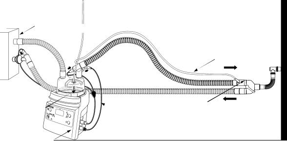
Ventilator/Gas Supply
 RT100 Breathing Circuit
Temperature Probe
 Chamber Probe
Airway Probe
MR290 Chamber
Heater Wire Adapter
MR850 Humidifier
Figure 4.1 Typical Heater Wire Humidifier Setup
Humidified gas from the chamber travels through the inspiratory limb, where its temperature must be maintained in order to prevent the generated humidity from condensing. This is achieved with a heater wire encapsulated within the inspiratory limb. The humidifier maintains the temperature along the inspiratory limb by monitoring the temperature at the airway probe and controlling the power delivered to the heater wire. Under normal conditions the gas is heated to 40 °C in the invasive mode, 34 °C for the non-invasive mode.
An optional, second heater wire, located in the expiratory limb, minimises condensate in this limb.
12 MR850 Technical Manual * Revision J * Issued November 2005 * Ref. 185041340 (185041713 internal)

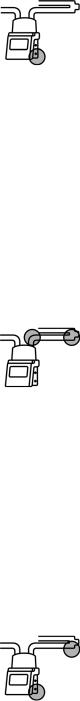
4.1.2Non-Heater Wire Operation (Software version 7.23 only)
Ventilator/Gas Supply
RT134 Breathing Circuit
Temperature Probe
Chamber
Probe
 Airway Probe
MR290
Chamber
Water trap
 MR850 Humidifier
Figure 4.2 Typical Non-Heater Wire Humidifier Setup
In this application the MR850 maintains the airway temperature at the desired set point (invasive 37 °C or non-invasive 31 °C) by heating the chamber of water through the heater plate. As the gas cools considerably down the unheated circuit, a water trap circuit must be used to collect the resulting condensate.
Activating Non-Heater Wire Operation
Refer also to the diagnostic menu in section 6.4.
1Turn on the humidifier with NO heated circuit connected, and mute the heater wire alarm.
2Access the diagnostic menu by pressing the mute and mode buttons together for 1 second, the display should show two rows of dashes ‘= = =’. Releasing both buttons will allow the diagnostic menu to cycle automatically.
3Allow the menu to cycle through to “cct” – the circuit identification. Press mute to access this function.
4To enable non-heated operation, press both mute and mode buttons simultaneously for 1 second, the humidifier will beep twice and the temperature display will show “nhh”. Release both buttons. The humidifier is now configured for non-heated circuits. This setting will be remembered each time the humidifier is turned on.
Deactivating Non-Heater Wire Operation
The simplest way to de-activate non heater wire operation is to connect a heated breathing circuit. Alternatively it can be de-activated the same way that non-heated circuit operation was activated (see above).
4.1.3Stand-by Operation
If the humidifier detects a problem with its setup or operation it will alarm. Depending on the severity of the alarm condition, the humidifier will either remove all power from the heating systems, or enter stand-by. The humidifier will also enter stand-by if the gas flow through the breathing circuit has stopped.
MR850 Technical Manual * Revision J * Issued November 2005 * Ref. 185041340 (185041713 internal) |
13 |
Stand-by (Software versions: 5.45 & 5.70)
•Heater wire power is set at 30 %.
•Control of chamber temperature is attempted, within the following limits:
•Heater plate temperature is limited to 60 °C.
•Heater plate power is limited to 20 %.
Stand-by (Software version: 6.00 onward)
•Heater wire power is set at 15 %.
•Control of chamber temperature is attempted, within the following limits:
•Heater plate temperature is limited to 50 °C.
•Heater plate power is limited to 20 %.
NOTE: The temperature alarm algorithm continues to function in stand-by.
4.1.4Power Up Sequence
The purpose of the power up sequence is to perform internal checks on various parts of the humidifier and provide the user with a visual and audible check.
Internal self test sequence:
1.Test presence of heater wire.
2.Test correct operation of heater wire triac.
3.Test correct operation of protection relays.
4.Test integrity of temperature/flow probe.
Visual/Audio test sequence:
1.The temperature display and indicator LEDs turn on.
2.The temperature display is blanked and indicators set to their default.
3.Display shows humidifier model number i.e. 850.
4.Display is blanked.
5.Display shows software version number.
6.Display is blanked and an audio tone of 2100 Hz sounds.
7.Normal display.
4.1.5Humidity Compensation (HC) mode (Software version 6.00 onward, except 7.23)
Normal ambient environments between 18 °C and 26 °C do not affect humidity output of temperature controlled heated humidifiers. However once the ambient temperature increases above 26 °C, and/or the temperature of the incoming gas becomes greater than 32 °C, e.g. due to ventilator heating, then the humidity output maybe reduced.
This can be identified by the lack of beading condensate on the inner walls of the humidification chamber and rectified by modifying the breathing circuit or humidifier settings. Increasing the length of breathing circuit between the ventilator and the humidification chamber will assist in cooling the gas before it enters the chamber and improve humidity output.
If beading condensate does not form, humidity output can be further improved by increasing the humidifier’s chamber set point. This can be achieved by accessing the HC mode (or Tc) in the Diagnostic Menu (see section 6.4) and either manually selecting a level of chamber temperature compensation or letting the automatic mode do it for you.
Automatic Humidity Compensation
When automatic HC mode is selected the humidifier calculates the power required to adequately humidify the gas flow through the chamber. If the minimum power level is not met
14 MR850 Technical Manual * Revision J * Issued November 2005 * Ref. 185041340 (185041713 internal)
then the chamber set point will automatically be increased in 0.5 °C steps (1 °C steps for noninvasive mode) until the minimum power is achieved. The maximum amount of compensation applied is either 3 or 5 °C depending on the mode and software version (section 6.4 Diagnostic Menu details how compensation is applied for each software version).
If conditions improve and too much power is being applied, then the MR850 will automatically reduce the chamber set temperature.
NOTE: Excessive condensate may form in the breathing circuit if the auto HC function is used with turbine driven ventilators (i.e. ventilators that use room air). It is recommended to switch off the auto HC function in these situations if the condensate becomes excessive.
NOTE: Auto HC function is factory set to enabled on all MR850 models.
Manual Humidity Compensation
For manual HC the level of compensation should be increased until beading condensate is observed on the inner walls of the humidification chamber. It should be noted that if environmental conditions change then it might be necessary to re-adjust this setting. For example, a fall in room temperature could produce a build up of unwanted condensate in the delivery circuit. A reduction in this setting may stop further build up.
NOTE: The previous manual HC setting is restored when power is applied to the humidifier
Refer to section 6.4 Diagnostic Menu for further information regarding this feature.
Activating/Deactivating Humidity Compensation
Refer also to the diagnostic menu in section 6.4
1.Access the diagnostic menu by pressing the mute and mode buttons together for 1 second, the diagnostic menu is entered, indicated by the display of two rows of dashes ‘= = =’. Releasing both buttons will allow the diagnostic menu to cycle automatically through the menu.
2.The first item is “HC” this is the humidity compensation item, press and hold mute to access this function.
3.The setting may show either ‘0’ or ‘-A-‘ to change the setting press both mute and mode buttons simultaneously for 1 second, the humidifier will beep twice and the setting will increase. Release both buttons.
4.To increase again repeat step 3. To decrease the setting press the mute and power buttons for 1 second.
5.To exit the menu, release all buttons, the menu will continue to cycle until ‘end’ is displayed, the menu will automatically exit.
Temperature Display
To alert users during normal operation that either manual or automatic HC mode has been enabled, the decimal point on the temperature display will flash. Each of the two modes can be further identified by the flash rate, where auto HC mode has a slower flash rate than manual HC mode.
Note: The displayed temperature may also be higher than normal indicating (up to 39°C) the amount of compensation present.
4.1.6Breathing Circuit Recognition (Software version 7.00 onward)
Fisher & Paykel Healthcare has developed a range of breathing circuits that offer optimum performance for the type of treatment selected while working within recommended operating conditions. Some of these breathing circuits require a slightly modified controller to optimize performance. To do this the MR850 must first recognize what type of delivery circuit has been
MR850 Technical Manual * Revision J * Issued November 2005 * Ref. 185041340 (185041713 internal) |
15 |

connected. Breathing circuit recognition is performed via three electrical connections on the heater wire adaptor. Re-configuring the electrical connection pins on a heated circuit and the way it connects to this adaptor identifies the type of heated circuit. In this way three separate heater wire circuits can be identified by the MR850.
4.2Humidifier Controls
4.2.1Power Button
The humidifier will power on if this button is held down briefly, but must be held for one second to turn the humidifier off.
Note: For software version 5.45, 5.70 the power button need only be pressed briefly to turn off the MR850.
CAUTION: Although the display is not illuminated, the unit may still be energized. Be sure to disconnect power from the MR850 before servicing.
After power-on the humidifier starts an internal diagnostic routine which checks for possible problems in the humidifier setup. If everything is working correctly, normal control is initiated.
4.2.2Mode Button
When held down for one second, the mode button toggles the humidifier between Non-Invasive and Invasive mode. The Mode indicator LED shows the user which mode is selected.
Invasive mode is for use with patients whose upper airways have been bypassed by either a tracheostomy or endotracheal tube. In this mode of operation the humidifier attempts to deliver optimal humidity to the patient (37 °C, 100 % RH). This mode is the default mode on power up of the humidifier.
The humidifier normally controls the chamber outlet temperature to 37 °C, and the airway temperature to 40 °C, maintaining a +3 °C temperature gradient along the inspiratory limb1.
If however this temperature gradient is not maintained, the chamber set point is reduced in 0.5 °C steps (minimum setting of 35.5 °C), in order to reduce condensate buildup in the breathing circuit2. If the chamber set point is less than 37 °C and sufficient temperature gradient has been maintained along the inspiratory limb, then the chamber set point is increased back up to 37 °C in 0.5 °C steps.
Non-Invasive mode is suitable only for patients whose natural humidification system (i.e. upper airways) has not been bypassed, but are receiving gas via a facemask or similar.
The humidifier normally controls the chamber outlet temperature to 31 °C, and the airway temperature to 34 °C, maintaining a +3 °C temperature gradient along the inspiratory limb1.
1If automatic or manual humidity compensation has been activated then the displayed temperature may be higher than 37 °C (Invasive mode) or 31 °C (Non-Invasive mode).
2The humidity compensation algorithm takes precedence over the condensation control algorithm.
16 MR850 Technical Manual * Revision J * Issued November 2005 * Ref. 185041340 (185041713 internal)
4.2.3Mute Button
The mute button silences the humidifier's audible alarm. The muted time depends on the alarm condition. In general, alarms will be muted for 2 minutes.
A chamber or airway probe alarm is muted for a longer time, until the humidifier determines whether the probe is in or out. The temperature alarm is treated differently - see section 4.5.
4.3Temperature Display
The front panel shows the lower of the chamber or airway temperatures. This temperature gives an indication of the dew point (in °C) of the gas that is being supplied to the patient. The dew point of a gas is the best indication of both its humidity and energy content. Under normal operation, the displayed temperature will be the chamber temperature, as its control set point is lower. If the temperature is above 70 °C, "Hi" will be displayed. If the temperature is below 10 °C, "Lo" will be displayed. If HC mode has been enabled the decimal point on the temperature display will flash.
4.3.1Showing Chamber and Airway Temperature
Both the chamber and airway temperature can be displayed by pushing and holding the mute button for 1 second. The temperatures are displayed in the following sequence:
1Chamber temperature is displayed until two seconds after the mute button is released. The chamber probe indicator (see section 4.4) will also light to show which temperature is being displayed.
2The display will blank, and then the airway temperature will be displayed until two seconds after the mute button is released. The airway probe indicator will also light (see section 4.4) to show which temperature is being displayed.
3The temperature display will blank again, and revert to normal operation.
4.4Setup Indicators
The MR850 setup indicators, placed on the lower left of the front panel, are intended to aid the user in identifying problems with the incorrect setup of the device and its accessories.
4.4.1Heater wire connector
These indicators light if the heater wire in the breathing circuit has not been connected correctly, or if the heater wire or heater wire adaptor is faulty. An intermittent connection, or excessive current (total current in all limbs > 3.5 A) in the heater wires will also produce this alarm. The humidifier will remove power from the heating systems if this alarm is active.
NOTE: Software versions 5.45 and 5.70 do not light the upper indicator located on the breathing circuit.
NOTE: Software versions 7.22 and 7.23 in non heater wire operation and without a heater wire connected no audible or visual heater wire alarm will be given. Connecting a heated wire circuit will automatically cause the MR850 to default to heater wire operation.
MR850 Technical Manual * Revision J * Issued November 2005 * Ref. 185041340 (185041713 internal) |
17 |
4.4.2Temperature / Flow Probe Connector
This indicator will light if the temperature probe is not correctly plugged in, or the probe used is faulty. The humidifier tests for the following probe fault conditions:
•Temperature probe disconnected
•Chamber thermistor open or short circuit
•Airway thermistor open or short circuit
•Flow thermistor open or short circuit (shorted probe test)
•One thermistor shorted to another (shorted probe test)
•Flow calibration resistor open or short circuit (shorted probe test)
An alarm will be generated if any of the above faults are found, and the humidifier will remove power from all heating systems.
NOTE: the shorted probe tests and flow thermistor tests are only performed on start-up, or when temperature probe or heater wire alarms are cancelled.
4.4.3Chamber Probe & Airway Probe
These indicators are used to show that either the chamber probe or airway probe is not inserted into the breathing circuit correctly. On start-up, and during rapid changes in temperature, the humidifier tests to see if a probe is in place by cooling and then heating the probe. If the humidifier finds that either probe is not inserted into the breathing circuit, an alarm will be generated and the humidifier will enter stand-by. During this alarm the humidifier will initiate a probe out test periodically, or a test will be initiated immediately after mute has been pressed.
During periods of low or zero gas flow, the airway probe out alarm is disabled. As soon as flow is detected however, an airway probe test is initiated.
NOTE: For software versions 7.22 and 7.23 in non-heater wire operation, the airway probe out alarm does not function, instead the low temperature of the disconnected probe will activate the temperature alarm (refer section 4.5).
4.4.4Chamber or Airway Probe Alarm with Probe connector alarm
The humidifier checks to see if the temperature probe is faulty by testing for the following conditions:
•Chamber temperature has been greater than 50 °C for 20 minutes
•Chamber temperature is greater than 80 °C
•Airway temperature has been greater than 50 °C for 5 minutes
•Airway temperature is greater than 80 °C
If an apparent fault is found, the humidifier will give a temperature / flow probe connector alarm, and also indicate either the chamber or airway probe. The humidifier will stay in stand-by until the chamber or airway temperature drops below 50 °C. Once this occurs, a probe test will also be initiated.
18 MR850 Technical Manual * Revision J * Issued November 2005 * Ref. 185041340 (185041713 internal)
4.4.5Water Out Indicator
This indicates that there is insufficient water in the humidification chamber.
The humidifier measures the amount of power used to obtain the chamber temperature. If a lower than expected amount of power is used, a 'water out' alarm is generated. It may take 15 minutes or longer to generate an alarm especially if there is a disturbance (change in flow).
This alarm can be cancelled by pressing the mute button. If however the water out condition remains, the humidifier will alarm again.
4.5Operational Alarms
These alarms are generated if problems occur with the operation of the humidifier.
4.5.1Temperature Indicator
This alarm will occur if the displayed temperature is too high, or if the delivered temperature (Invasive mode only) has been low for a period of time.
High temperature:
The humidifier will immediately alarm if at any time the displayed temperature exceeds 41 °C, or if the airway temperature exceeds 43 °C. If either of these high temperature alarms occur, the humidifier will immediately shut down the heater wire and heater plate.
Low Temperature:
The low temperature warning (visual only) and alarm (visual and audible) are active only when the humidifier is in Invasive mode. Both are disabled during warm-up conditions. The warning alerts the user that low temperature is being delivered to the patient. The alarm alerts the user that a low level has been delivered to an Invasive patient for too long.
The low temperature warning and alarm operate by monitoring the displayed temperature. If the displayed temperature is below 35.5 °C for 25 seconds, the temperature indicator will light, and act as a warning to the user. If the temperature remains below this level for too long, then a Temperature Alarm is activated. The time taken for the humidifier to alarm is dependent on how far below the 35.5 °C threshold the displayed temperature is. Figure 4.3 shows the relationship between temperature, a temperature warning and the time before a temperature alarm:
MR850 Technical Manual * Revision J * Issued November 2005 * Ref. 185041340 (185041713 internal) |
19 |
 Loading...