


DishDrawer®
DD607 & DD247
Service Manual
NZ AU GB IE US CA
FEATURED PRODUCT & CONTACT ADDRESSES
Brand: |
Fisher & Paykel |
|
|
|
||
|
|
|
|
|
||
Standard Double |
|
Description |
Product Codes - |
|
||
Models |
|
|
|
Markets |
|
|
DD24DCW7 |
|
Double, Classic White |
88636-US / CA |
|
|
|
DD24DCX7 |
|
Double, Classic Brushed Stainless Steel |
88637-US / CA |
|
|
|
DD24DI7 |
|
Double , Integrated |
88639-US / CA |
|
|
|
DD24DCB7 |
|
Double, Classic Black |
88641-US / CA |
|
|
|
DD24DDFX7 |
|
Double, Designer, Brushed Stainless |
88642-US / CA |
|
|
|
DD60DCHX7 |
|
Double Classic Brushed Stainless, Water Softener |
89383-GB |
|
|
|
|
|
|
|
89394-EU |
|
|
|
|
|
|
89403-DK |
|
|
|
|
|
|
85070-TW |
|
|
DD60DHI7 |
|
Double, Integrated, Water Softener |
89384-GB |
|
|
|
|
|
|
|
89395-EU |
|
|
|
|
|
|
89404-DK |
|
|
|
|
|
|
85071-TW |
|
|
DD60DCHB7 |
|
Double, Classic Black, Water Softener |
89385-GB |
|
|
|
DD60DDFHX7 |
|
Double, Designer, Brushed Stainless, Water Sof- |
89386-GB |
|
|
|
|
|
tener |
|
89396-EU |
|
|
|
|
|
|
89405-DK |
|
|
DD60DCHW7 |
|
Double, Classic White, Water Softener |
89382-GB |
|
|
|
|
|
|
|
89402-DK |
|
|
|
|
|
|
85069-TW |
|
|
DD60DI7 |
|
Double Integrated |
80769-AA |
|
|
|
DD60DCM7 |
|
Double, Classic Iridium Stainess |
80770-AA |
|
|
|
DD60DCW7 |
|
Double, Classic White |
80767-AA |
|
|
|
DD60DCX7 |
|
Double, Classic Brushed Stainless |
80768-AA |
|
|
|
DD60DDFM7 |
|
Double, Designer, Iridium |
80771-AA |
|
|
|
DD60DDFX7 |
|
Double, Designer, Brushed Stainless |
80772-AA |
|
|
|
Fisher & Paykel Appliances Ltd |
Fisher & Paykel Customer Services Pty Ltd |
Fisher & Paykel Appliances Ltd |
||||
PO Box 58-732, Botany |
|
PO Box 798, Cleveland, QLD 4163 |
Singapore |
|
|
|
78 Springs Rd, East Tamaki |
|
A.C.N. 003 3335 171 |
150 Ubi Avenue 4 |
|||
Manukau 2163 |
|
|
19 Enterprise Street Cleveland, QLD 4163 |
Sunlight building #02-00 |
||
New Zealand |
|
|
Australia |
Singapore 408825 |
||
tel: (09) 2730660 |
|
|
tel: (07) 3826 9100 |
tel: |
6547 0100 |
|
fax: (09) 2730580 |
|
|
fax: (07) 3826 9164 |
service tel: |
6741 0777 |
|
email: customer.care@fp.co.nz |
|
email: customer.care@fp.com.au |
fax: |
6547 0123 |
||
Fisher & Paykel Appliances Ltd U.K |
Fisher & Paykel Appliances |
Fisher & Paykel Appliances Inc. |
||||
Maidstone Road |
|
|
Unit D2 |
5900 Skylab Rd, |
|
|
Kingston |
|
|
North Dublin Corporate Park |
Huntington Beach |
||
Milton Keynes |
|
|
Swords |
California, CA92647 |
||
Buckinghamshire |
|
|
Co Dublin |
USA |
|
|
England, MK10 0BD |
|
|
Ireland |
tel: 888 936 7872 |
|
|
|
|
|
|
|
|
|
tel: 0845 066 2200 |
|
|
tel: 1800 625 174 |
email: customer.care@fisherpaykel.com |
||
fax: 0845 331 2360 |
|
|
fax: 1800 635 012 |
|
|
|
email: customer.care@fisherpaykel.co.uk email: customer.care@fisherpaykel.ie |
|
|
|
|||
Standard Single |
Description |
Product Codes - |
Models |
|
Markets |
DD24SCW7 |
Single, Classic White |
88629-US / CA |
DD24SCX7 |
Single, Classic Brushed Stainless Steel |
88630-US / CA |
DD24SI7 |
Single , Integrated |
88632-US / CA |
DD24SCB7 |
Single, Classic Black |
88634-US / CA |
DD24SDFX7 |
Single, Designer, Brushed Stainless |
88635-US / CA |
DD60SCHX7 |
Single, Classic Brushed stainless, Water Sof- |
89388-GB |
|
tener |
89397-EU |
|
|
89407-DK |
|
|
85073-TW |
DD60SHI7 |
Single, Integrated, Water Softener |
89389-GB |
|
|
89398-EU |
|
|
89408-DK |
|
|
85074-TW |
DD60SCHB7 |
Single, Classic Black, Water Softener |
89390-GB |
DD60SDFHX7 |
Single, Designer, Brushed Stainless, Water |
89391-GB |
|
Softener |
89366-EU |
|
|
89409-DK |
DD60SCHW7 |
Single, Classic White, Water Softener |
89387-GB |
|
|
89406-DK |
|
|
85072-TW |
DD60SI7 |
Single, Integrated |
80775-AA |
DD60SCW7 |
Single, Classic White |
80773-AA |
DD60SCX7 |
Single, Classic Brushed Stainless |
80774-AA |
DD60SHLI7 |
Single, Integrated, Water Softener, Long Door |
89411-DK |
DD60SDFX7 |
Single, Designer, Brushed Stainless |
80776-AA |
Tall Tub Double |
Description |
Product Codes - |
Models |
|
Markets |
DD24DDFTX7 |
Double Designer, Brushed Stainless, Tall Tub |
88620-US / CA |
DD24DTI7 |
Double Integrated, Tall Tub |
88622-US / CA |
DD24DCTX7 |
Double, Classic, Brushed Stainless, Tall Tub |
88626-US / CA |
DD24DCHTX7 |
Double, Classic, Brushed Stainless, Water |
88638-US / CA |
|
Softener |
|
DD24DHTI7 |
Double, Itegrated, Water Softener |
88640-US / CA |
DD24DCTW7 |
Double, Tall Tub, Classic White |
88628-US / CA |
DD24DCTB7 |
Double, Tall Tub, Classic Black |
88624-US / CA |
Tall Tub Single |
Description |
Product Codes - |
Models |
|
Markets |
DD24SDFTX7 |
Single, Designer, Tall Tub, Brushed Stainless |
88621-US / CA |
DD24STI7 |
Single, Integrated, Tall Tub |
88623-US / CA |
DD24SCHTX7 |
Single, Classic, Tall Tub, Brushed Stainless |
88631-US / CA |
|
Steel |
|
DD24SCTW7 |
Single, Tall Tub, Classic White |
88643-US / CA |
DD24SCTB7 |
Single, Tall Tub, Classic Black |
88625-US / CA |
DD24SHTI7 |
Single, Integrated, Water Softener, Tall Tub |
88633-US / CA |
DD24SCTX7 |
Single, Classic, Tall Tub, Brushed Stainless, |
88627-US / CA |
DD60SHTI7 |
Single, Integrated, Tall Tub, Water Softener |
89381-GB |
|
|
89393-EU |
DD60SDFHTX7 |
Single, Designer, Brushed Stainless, Tall Tub, |
89380-GB |
|
Water Softener |
89392-EU |
DD60SDFTX7 |
Single, Designer, Brushed Stainless, Tall Tub |
80761-AA |
DD60SDFTM7 |
Single, Designer, Iridium Stainless, Tall Tub |
80763-AA |
DD60STI7 |
Single, Integrated, Tall Tub |
80762-AA |
DD60SCTW7 |
Single, Tall Tub, Classic White |
80764-AA |
DD60SCTX7 |
Single, Tall Tub, Classic, Stainless Steel |
80765-AA |
DD60SCTM7 |
Single, Tall Tub, Classic, Iridium Stainless |
80766-AA |
DD60SDFHTX7 |
Single, Designer, Water Softener, Tall Tub |
89400-DK |
DD60SHTI7 |
Single, Integrated, Water Softener, Tall Tub |
89401-DK |
DD60SHTLI7 |
Single, Integrated,Water Softener, Tall Tub, |
89410-DK |
|
Long Door |
|
CONTENTS
1 |
SERVICE REQUIREMENTS |
7 |
1.1 |
Health & Safety |
7 |
1.2 |
Specialised Tools |
8 |
2 |
DIMENSIONS & SPECIFICATIONS |
9 |
3 |
TECHNICAL OVERVIEW |
14 |
3.1 Chassis |
14 |
|
3.2 Drawer Fronts |
14 |
|
3.3 Electronics |
14 |
|
3.4 Motor |
16 |
|
3.5 Lid System |
18 |
|
3.6 Tub |
18 |
|
3.7 Filling |
18 |
|
3.8 Heating |
20 |
|
3.9 Motor and Heater Plate Locknuts |
21 |
|
3.10 Drain Cycle |
21 |
|
3.11 Filter Plate |
22 |
|
3.12 Drying Cycle |
23 |
|
3.13 Water Softener (if fitted) |
24 |
|
4 |
OPTION ADJUSTMENT MODE |
25 |
4.1 How to Change the Setup Options (Classic, Designer & Integrated models) |
25 |
|
4.2 Option Adjustment Quick Reference Charts |
27 |
|
5 |
DIAGNOSTICS |
30 |
5.1 DishDrawer Diagnostics |
30 |
|
5.2 DishDrawer Diagnostics Wireless Badge Models |
34 |
|
6 |
FAULT CODES AND POOR PERFORMANCE |
36 |
6.1 Fault Code Description Chart |
37 |
|
6.1.1 Sub Code Faults |
38 |
|
6.2 Poor Dry Performance |
40 |
|
6.3 Poor Wash Performance |
41 |
|
7 |
FAULT FINDING PROCEDURE |
44 |
7.2 Completing a Service |
54 |
|
8 |
WIRING DIAGRAMS |
55 |
8.2 Wiring Diagram |
56 |
|
9 |
SERVICE PROCEDURES |
57 |
9.1 Component Testing |
57 |
|
9.2 Drawer Front |
58 |
|
9.3 Handle and LCD Display |
58 |
|
9.4 Toe Kick Removal |
59 |
|
9.5 Lower Tub Cowling |
59 |
|
9.6 Tub Removal |
59 |
|
9.7 Drying Duct - Top Tub Only |
60 |
|
9.8 Drying Fan and Flap Valve |
60 |
|
9.9 Detergent Dispenser |
61 |
|
9.10 Electronic Controller |
61 |
|
9.11 Filter Plate |
62 |
|
9.12 Motor Rotor |
62 |
|
9.13 Water Softener (if fitted) |
63 |
|
9.14 Strainer (if fitted) |
63 |
|
9.15 Wiring Cover |
64 |
|
9.16 Tub Disconnection |
64 |
|
9.17 Hall Sensor |
65 |
|
9.18 Heater Plate and Motor Assembly |
65 |
|
9.19 Lid |
66 |
|
9.20 Yoke |
68 |
|
9.21 Lid Actuator |
68 |
|
9.22 Slide Rail Replacement. |
69 |
|
9.23 Mains Filter Cover and PCB Mains Filter |
69 |
|
9.24 Water Inlet Valve |
70 |
|
9.25 Fill Hose, Drain Hose, Wiring Harness Replacement |
70 |
|
9.26 Link Support Wire Position |
70 |
|
9.27 Front Chassis Trim Replacement |
71 |
|
9.28 Single Integrated Vent Duct Removal |
71 |
|
9.29 Internal Duct and Elbow Removal |
72 |
|
9.30 Wireless Receiver & Badge Remote |
73 |
|
10 NOTES |
76 |

71 SERVICE REQUIREMENTS
1.1Health & Safety
Note: When servicing the DishDrawer™, Health and Safety issues must be considered at all times. Specific safety issues are listed below with their appropriate icon. These are illustrated throughout the service
information to remind service people of the Health and Safety issues.
1.1.1 Electrical Safety
Ensure the mains power has been disconnected before servicing the DishDrawer™. If the mains supply is required to be on to service the DishDrawer™, make sure it is turned off when removing any electrical component or connection to avoid electrical shock.
1.1.2 Electrostatic Discharge
An anti-static strap is to be used as electrical static discharge (ESD) protection when servicing electronic components.
1.1.3 Good Working Practices
Ensure the work area is in a tidy and orderly condition at all times so as not to cause a hazard while service work is being completed. Always clean and tidy the DishDrawer™ and work area after service is completed.
1.1.4 Isolate Water Supply
Turn off the water connection tap before servicing.
1.1.5 Water Leak Check
Check for water leaks as part of the testing after the service has been completed.
1.1.6 Insulation Test
Megger test to check insulation.
Warning: Short together the phase and neutral pins on the plug so as not to damage any electronic circuitry.
1.1.7 Solvent and Excessive Heat Damage
Solvents and excessive heat can damage plastic surfaces.
1.1.8 Sheet Metal Edges
|
When working around cut sheet metal edges use appropriate gloves or protection to eliminate |
|
the chance of receiving a laceration. |
1.1.9 Diagnostics |
|
D |
While in diagnostics some safety devices are bypassed. Ensure you do not run components |
unattended. They may overheat, flood, burn out or cause water damage. |
|

8
1.2 Specialised Tools
For servicing this product, specialised tools are required.
1.2.1 Static Strap
To be used as ESD (electrostatic discharge) protection when replacing or handling electronic components.

9 2 DIMENSIONS & SPECIFICATIONS
Product Dimensions
Standard Product |
Product Size |
Product Size |
Minimum Cavity |
Minimum Cavity |
|
(mm) |
(inches) |
Size (mm) |
Size (inches) |
Height (Double) |
820 -880mm |
34 5/8” |
820mm |
32 5/16” |
Height Single |
410mm |
16 1/8” |
412mm |
16 1/4” |
Width |
599mm |
23 9/16” |
600mm |
23 5/8” |
Depth (classic) |
582mm |
22 15/16” |
560mm |
22 1/16” |
Depth (FD & IN) |
571mm |
22 1/2” |
560mm |
22 1/16” |
Tall Tub Product |
Product Size |
Product Size |
Minimum Cavity |
Minimum Cavity |
|
(mm) |
(inches) |
Size (mm) |
Size (inches) |
Height (Double) |
864-924mm |
34-36 3/8” |
864mm |
34” |
Height Single |
454mm |
17 7/8” |
456mm |
18” |
( classic) |
|
|
|
|
Height Single |
454-478mm |
177/8” - 1813/16” |
480mm |
18 7/8” |
(FD & IN) |
|
|
|
|
Width |
599mm |
23 9/16” |
600mm |
23 5/8” |
Depth (Classic |
582mm |
22 15/16” |
560mm |
22 1/16” |
Depth (FD & IN) |
571mm |
22 1/2” |
560mm |
22 1/16” |
NOTE: For more detailed installation measurements refer to the installation guides on CBW. www.cbw.fp.co.nz
Electrical Specifications
Market |
Voltage |
Frequency |
Current Double/Single |
|
AA / GB / EU / DK |
230/240 V |
50/60 Hz |
10 |
/ 5 A |
USA / CA / TW |
110 /120 V |
60 Hz |
10.6 |
/ 5.3 A |

10
Component Specifications
Component |
|
Specification |
Controller |
NZ, AU, GB, EU, DK |
230V |
|
US, CA, TW |
120V |
Water Inlet Valve |
all markets |
24V DC |
|
|
65+/- 10 Ohms per coil |
|
|
2.5litres/min (0.65 US gal/min) |
Dispenser Coils |
all markets |
24V DC per coil |
|
|
65+/- 10 Ohms per coil |
Rinse Aid Tank |
all markets |
50mls (approx. 25 washes) |
|
|
3.05 cubic inches |
PCB Mains Filter |
NZ, AU, GB, EU, DK |
230V AC |
(2 Types - Single / Double) |
US, CA, TW |
110V AC |
Motor |
|
80V DC 3 Phase Brushless |
Drain Speed |
Pump out rate 5 litres / min. |
5000 RPM |
Wash Speed |
|
2200 - 2800 RPM |
Stator |
|
8.0 Ohms (per winding), 16 ohms phase to |
|
|
phase from the controller connector |
Heater plate 230V |
NZ, AU, GB, EU, DK |
230V AC |
Wattage |
|
1045W |
Water Heater Track |
|
50 Ohms +/- 4 Ohms |
Power Supply Resistor |
|
98 Ohms +/- 7 Ohms |
Temperature Sensor |
Located on the heater plate |
12000 Ohms @ 20 oC |
|
|
8300 Ohms @ 30 oC |
|
|
3000 Ohms @ 60 oC |
Heater Plate 110V |
US, CA, TW |
120V AC |
Wattage |
|
650W |
Water Heater Track |
|
24 Ohms +/- 3 Ohms |
Power Supply Resistor |
|
24 Ohms +/- 3 Ohms |
Temperature Sensor |
Located on the heater plate |
12000 Ohms @ 68 oF |
|
|
8300 Ohms @ 86 oF |
|
|
3000 Ohms @ 140 oF |
Fusible link |
Located on the heater plate |
268 – 302 oC (514 – 576 oF) |
Water Inlet hose |
Pressure Rating |
1MPa (145psi) |
|
Length from chassis edge |
1650mm (64 ¾” ) left hand side |
|
(viewed from the front) |
1250mm (49”) Right hand side |
Water Pressure |
Non water softener models |
1MPa (145 psi) max, |
|
|
0.03 MPa (4.3psi) min |
|
Water softener models |
1MPa (145psi) max, |
|
|
0.1MPa (14.5psi) min |
Drain Hose |
|
2000 mm (78 ½” )from left hand side |
|
|
1800mm (70 ½”) from right hand side. |
Power Cord |
NZ, AU, GB, EU, DK |
1650mm |
|
length from chassis exit when |
|
|
product viewed from the front |
|
|
US, CA, TW |
29 ½” LH side, 27 ½” RH side |
11
Component |
|
Specification |
Drying Fan |
|
24V brushless DC motor |
|
|
0.27A |
|
|
only replace if open or short circuit |
Diverter valve water softener |
|
24V DC Coil |
|
|
65 +/- 10 Ohms Coil |
Brine pump assembly |
|
24V DC Coil |
|
|
65 +/- 10 Ohms Coil |
Water softener |
|
500 grams Salt Capacity |
|
|
approx. 14 regenerations |
|
|
290+/- 10ml Resin |
Lid actuator |
|
24V DC |
|
|
Only replace if open or short circuit. |
Hall sensor |
|
5 V DC |
LCD |
5 volt rail between pins 2&5 |
LCD has a back light |
Performance
NZ/AU
Based on 7 wash loads per week, using normal eco program
|
Per Tub |
Star Rating |
Energy |
134 KwH |
3.5 |
Water |
6.7L |
4.5 |
GB, EU
Per Tub |
Energy |
Wash |
Dry |
|
A |
A |
A |
|
0.64 |
|
|
US, CA, TW
Based on 4 wash loads per week
Product |
Energy |
Single |
141 kWh |
Single Integrated |
155 kWh |
Double |
276 kWh |

12
Wash Profiles (Non Vented)
NZ, AU
Incoming @ 20°C |
|
|
|
|
|
|
|
|
|
|
|
|
|
|
|
|
|
|
Wash Cycle |
D |
F |
Wash |
D |
F |
Post |
D |
F |
Post |
D |
F |
Final Rinse |
D |
Dry |
Time |
Total |
Fan run |
|
|
|
|
|
|
|
|
Rinse 1 |
|
|
Rinse 2 |
|
|
|
|
|
(min) |
Water |
on (min) |
Heavy |
Time (min) |
1 |
1 |
46 |
2 |
1 |
10 |
2 |
1 |
10 |
2 |
1 |
15 |
2 |
30 |
124 |
10.4 |
120 |
@2800rpm |
Temp (°C) |
|
|
70°C |
|
|
|
|
|
|
|
|
65°C |
|
|
|
|
|
|
Fill (L) |
|
|
2.7 |
|
|
2.5 |
|
|
2.5 |
|
|
2.7 |
|
|
|
|
|
Heavy Eco |
Time (min) |
1 |
1 |
41 |
2 |
1 |
6 |
2 |
1 |
6 |
2 |
1 |
24 |
2 |
30 |
120 |
10.6 |
120 |
@2500-2600rpm |
Temp (°C) |
|
|
65°C |
|
|
|
|
|
|
|
|
55°C |
|
|
|
|
|
|
Fill (L) |
|
|
2.7 |
|
|
2.7 |
|
|
2.5 |
|
|
2.7 |
|
|
|
|
|
Normal |
Time (min) |
1 |
1 |
55 |
2 |
1 |
10 |
2 |
|
|
|
1 |
33 |
2 |
20 |
128 |
7.6 |
120 |
@2400-2600rpm |
Temp (°C) |
|
|
60°C |
|
|
|
|
|
|
|
|
60°C |
|
|
|
|
|
|
Fill (L) |
|
|
2.3 |
|
|
2.8 |
|
|
|
|
|
2.5 |
|
|
|
|
|
Normal Eco |
Time (min) |
|
1 |
40 |
2 |
1 |
10 |
2 |
|
|
|
1 |
35 |
2 |
55 |
149 |
6.6 |
30 |
@2200rpm |
Temp (°C) |
|
|
39°C |
|
|
|
|
|
|
|
|
40°C |
|
|
|
|
|
|
Fill (L) |
|
|
2.3 |
|
|
2.1 |
|
|
|
|
|
2.2 |
|
|
|
|
|
Delicate |
Time (min) |
1 |
1 |
26 |
2 |
1 |
4 |
2 |
1 |
4 |
2 |
1 |
15 |
2 |
30 |
92 |
10 |
120 |
@2300rpm |
Temp (°C) |
|
|
50°C |
|
|
|
|
|
|
|
|
60°C |
|
|
|
|
|
|
Fill (L) |
|
|
2.5 |
|
|
2.5 |
|
|
2.5 |
|
|
2.5 |
|
|
|
|
|
Delicate Eco |
Time (min) |
1 |
1 |
21 |
2 |
1 |
3 |
2 |
1 |
3 |
2 |
1 |
10 |
2 |
30 |
80 |
10 |
120 |
@2300rpm |
Temp (°C) |
|
|
45°C |
|
|
|
|
|
|
|
|
50°C |
|
|
|
|
|
|
Fill (L) |
|
|
2.5 |
|
|
2.5 |
|
|
2.5 |
|
|
2.5 |
|
|
|
|
|
Fast |
Time (min) |
1 |
1 |
22 |
2 |
1 |
2 |
2 |
|
|
|
1 |
10 |
2 |
5 |
49 |
7.5 |
120 |
@2500rpm |
Temp (°C) |
|
|
55°C |
|
|
|
|
|
|
|
|
55°C |
|
|
|
|
|
|
Fill (L) |
|
|
2.5 |
|
|
2.5 |
|
|
|
|
|
2.5 |
|
|
|
|
|
Fast Eco |
Time (min) |
1 |
1 |
12 |
2 |
1 |
2 |
2 |
|
|
|
1 |
7 |
2 |
2 |
33 |
7.5 |
30 |
@2700rpm |
Temp (°C) |
|
|
45°C |
|
|
|
|
|
|
|
|
45°C |
|
|
|
|
|
|
Fill (L) |
|
|
2.5 |
|
|
2.5 |
|
|
|
|
|
2.5 |
|
|
|
|
|
Rinse |
Time (min) |
1 |
1 |
7 |
2 |
|
|
|
|
|
|
|
|
|
|
11 |
2.5 |
|
@2300rpm |
Temp (°C) |
|
|
|
|
|
|
|
|
|
|
|
|
|
|
|
|
|
|
Fill (L) |
|
|
2.5 |
|
|
|
|
|
|
|
|
|
|
|
|
|
|
GB, EU
Incoming Water 15°C |
|
|
|
|
|
|
|
|
|
|
|
|
|
|
|
|
|
|
|
|
|
Wash Cycle |
D |
F |
Prewash |
D |
F |
Main Wash |
D |
F |
Post |
D |
F |
Post |
D |
F |
Final Rinse |
D |
Dry |
Time |
Fills (L) |
Fan run |
|
|
|
|
|
|
|
|
|
|
|
Rinse 1 |
|
|
Rinse 2 |
|
|
|
|
|
(min) |
|
on (min) |
Heavy |
Time (min) |
|
|
|
1 |
1 |
57 |
2 |
1 |
4 |
2 |
1 |
4 |
2 |
1 |
18 |
2 |
30 |
126 |
12.8 |
120 |
2800rpm |
Temp (°C) |
|
|
|
|
|
70°C |
|
|
|
|
|
|
|
|
65°C |
|
|
|
|
|
|
Fill (L) |
|
|
|
|
|
3.2 |
|
|
3.2 |
|
|
3.2 |
|
|
3.2 |
|
|
|
|
|
Heavy Eco |
Time (min) |
|
|
|
1 |
1 |
41 |
2 |
1 |
4 |
2 |
1 |
4 |
2 |
1 |
14 |
2 |
45 |
121 |
10.7 |
120 |
2800rpm |
Temp (°C) |
|
|
|
|
|
60°C |
|
|
|
|
|
|
|
|
55°C |
|
|
|
|
|
|
Fill (L) |
|
|
|
|
|
3.2 |
|
|
2.5 |
|
|
2.5 |
|
|
2.5 |
|
|
|
|
|
Normal |
Time (min) |
|
|
|
1 |
1 |
32 |
2 |
1 |
3 |
2 |
1 |
3 |
2 |
1 |
19 |
2 |
25 |
95 |
12.8 |
120 |
2650rpm |
Temp (°C) |
|
|
|
|
|
65°C |
|
|
|
|
|
|
|
|
65°C |
|
|
|
|
|
|
Fill (L) |
|
|
|
|
|
3.2 |
|
|
3.2 |
|
|
3.2 |
|
|
3.2 |
|
|
|
|
|
Normal Eco |
Time (min) |
1 |
1 |
12 |
|
|
43 |
2 |
1 |
30 |
2 |
|
|
|
1 |
24 |
2 |
40 |
159 |
8* |
30 |
2400rpm |
Temp (°C) |
|
|
42°C |
|
|
50°C |
|
|
|
|
|
|
|
|
60°C |
|
|
|
|
|
|
Fill (L) |
|
|
2.5 |
|
|
Fill valve 12s* |
|
|
2.5 |
|
|
|
|
|
2.5 |
|
|
|
|
|
Delicate |
Time (min) |
|
|
|
1 |
1 |
26 |
2 |
1 |
4 |
2 |
1 |
4 |
2 |
1 |
15 |
2 |
30 |
92 |
10 |
120 |
2300rpm |
Temp (°C) |
|
|
|
|
|
50°C |
|
|
|
|
|
|
|
|
60°C |
|
|
|
|
|
|
Fill (L) |
|
|
|
|
|
2.5 |
|
|
2.5 |
|
|
2.5 |
|
|
2.5 |
|
|
|
|
|
Delicate Eco |
Time (min) |
|
|
|
1 |
1 |
24 |
2 |
1 |
7 |
2 |
1 |
3 |
2 |
1 |
10 |
2 |
30 |
87 |
10 |
120 |
2300rpm |
Temp (°C) |
|
|
|
|
|
45°C |
|
|
|
|
|
|
|
|
50°C |
|
|
|
|
|
|
Fill (L) |
|
|
|
|
|
2.5 |
|
|
2.5 |
|
|
2.5 |
|
|
2.5 |
|
|
|
|
|
Fast |
Time (min) |
|
|
|
1 |
1 |
26 |
2 |
1 |
2 |
2 |
|
|
|
1 |
10 |
2 |
5 |
53 |
7.5 |
120 |
2500rpm |
Temp (°C) |
|
|
|
|
|
55°C |
|
|
|
|
|
|
|
|
50°C |
|
|
|
|
|
|
Fill (L) |
|
|
|
|
|
2.5 |
|
|
2.5 |
|
|
|
|
|
2.5 |
|
|
|
|
|
Fast Eco |
Time (min) |
|
|
|
1 |
1 |
16 |
2 |
1 |
2 |
2 |
|
|
|
1 |
10 |
2 |
1 |
39 |
7.5 |
30 |
2500rpm |
Temp (°C) |
|
|
|
|
|
45°C |
|
|
|
|
|
|
|
|
45°C |
|
|
|
|
|
|
Fill (L) |
|
|
|
|
|
2.5 |
|
|
2.5 |
|
|
|
|
|
2.5 |
|
|
|
|
|
Rinse |
Time (min) |
1 |
1 |
7 |
2 |
|
|
|
|
|
|
|
|
|
|
|
|
|
11 |
3.2 |
|
2300rpm |
Temp (°C) |
|
|
|
|
|
|
|
|
|
|
|
|
|
|
|
|
|
|
|
|
|
Fill (L) |
|
|
3.2 |
|
|
|
|
|
|
|
|
|
|
|
|
|
|
|
|
|
US, CA |
(49°C) |
|
|
|
|
|
|
|
|
|
|
|
|
|
|
|
|
|
|
|
|
|
|
Incoming @ 120°F |
|
|
|
|
|
|
|
|
|
|
|
|
|
|
|
|
|
|
|
|
|
|
Wash Cycle |
D |
F |
Main Wash |
D |
F |
Post Rinse 1 |
D |
F |
Post |
D |
F |
Post |
D |
F |
Final Rinse |
D |
Dry |
Time |
Water |
Fan Run |
|
|
|
|
|
|
|
|
|
|
|
|
Rinse 2 |
|
|
Rinse 3 |
|
|
|
|
|
(min) |
(L) |
on |
|
Heavy |
Time (min) |
1 |
1 |
36 |
2 |
1 |
21 |
2 |
1 |
3 |
2 |
1 |
3 |
2 |
1 |
20 |
2 |
28 |
127 |
13.9 |
120 |
|
@2800rpm |
Temp |
|
|
65°C/149°F |
|
|
|
|
|
|
|
|
|
|
|
70°C/158 °F |
|
|
|
|
|
|
|
Fill (L) |
|
|
3.2 |
|
|
3.2 |
|
|
2.5 |
|
|
2.5 |
|
|
2.5 |
|
|
|
|
|
|
Heavy Eco |
Time (min) |
1 |
1 |
31 |
2 |
1 |
14 |
2 |
1 |
3 |
2 |
1 |
3 |
2 |
1 |
15 |
2 |
25 |
107 |
12.5 |
120 |
|
@2800rpm |
Temp |
|
|
65°C/149°F |
|
|
|
|
|
|
|
|
|
|
|
65°C/149°F |
|
|
|
|
|
|
|
Fill (L) |
|
|
2.5 |
|
|
2.5 |
|
|
2.5 |
|
|
2.5 |
|
|
2.5 |
|
|
|
|
|
|
Normal |
Time (min) |
1 |
1 |
20 |
2 |
1 |
40 |
2 |
1 |
10 |
2 |
|
|
|
1 |
20 |
2 |
25 |
128 |
12 |
120 |
|
@2800rpm |
Temp |
|
|
50°C/122°F |
|
|
55°C /131°F |
|
|
|
|
|
|
|
|
55°C/131°F |
|
|
|
|
|
|
|
Fill (L) |
|
|
3.0 |
|
|
3.0 |
|
|
3.0 |
|
|
|
|
|
3.0 |
|
|
|
|
|
|
Normal Eco |
Time (min) |
1 |
1 |
38 |
2 |
1 |
10 |
2 |
|
|
|
|
|
|
1 |
20 |
2 |
22 |
100 |
7.6 |
30 |
|
@2400rpm |
Temp |
|
|
48°C/118°F |
|
|
|
|
|
|
|
|
|
|
|
52°C/125°F |
|
|
|
|
|
|
|
Fill (L) |
|
|
2.6 |
|
|
2.5 |
|
|
|
|
|
|
|
|
2.5 |
|
|
|
|
|
|
Delicate |
Time (min) |
1 |
1 |
21 |
2 |
1 |
5 |
2 |
1 |
3 |
2 |
|
|
|
1 |
15 |
2 |
25 |
82 |
10 |
120 |
|
@2300rpm |
Temp |
|
|
50°C/122°F |
|
|
|
|
|
|
|
|
|
|
|
55°C/131°F |
|
|
|
|
|
|
|
Fill (L) |
|
|
2.5 |
|
|
2.5 |
|
|
2.5 |
|
|
|
|
|
2.5 |
|
|
|
|
|
|
Delicate Eco |
Time (min) |
1 |
1 |
19 |
2 |
1 |
5 |
2 |
1 |
3 |
2 |
|
|
|
1 |
12 |
2 |
16 |
68 |
10 |
120 |
|
@2300rpm |
Temp |
|
|
45°C/113°F |
|
|
|
|
|
|
|
|
|
|
|
50°C/122°F |
|
|
|
|
|
|
|
Fill (L) |
|
|
2.5 |
|
|
2.5 |
|
|
2.5 |
|
|
|
|
|
2.5 |
|
|
|
|
|
|
Fast |
Time (min) |
1 |
1 |
26 |
2 |
1 |
2 |
2 |
|
|
|
|
|
|
1 |
10 |
2 |
5 |
53 |
7.5 |
120 |
|
@2500rpm |
Temp |
|
|
55°C/131°F |
|
|
|
|
|
|
|
|
|
|
|
50°C/122°F |
|
|
|
|
|
|
|
Fill (L) |
|
|
2.5 |
|
|
2.5 |
|
|
|
|
|
|
|
|
2.5 |
|
|
|
|
|
|
Fast Eco |
Time (min) |
1 |
1 |
11 |
2 |
1 |
3 |
2 |
|
|
|
|
|
|
1 |
9 |
2 |
2 |
35 |
7.5 |
30 |
|
@2500rpm |
Temp |
|
|
45°C/113°F |
|
|
|
|
|
|
|
|
|
|
|
45°C/113°F |
|
|
|
|
|
|
|
Fill (L) |
|
|
2.5 |
|
|
2.5 |
|
|
|
|
|
|
|
|
2.5 |
|
|
|
|
|
|
Rinse |
Time (min) |
1 |
1 |
7 |
2 |
|
|
|
|
|
|
|
|
|
|
|
|
|
11 |
2.5 |
|
|
@2300rpm |
Temp |
|
|
|
|
|
|
|
|
|
|
|
|
|
|
|
|
|
|
|
|
|
|
Fill (L) |
|
|
2.5 |
|
|
|
|
|
|
|
|
|
|
|
|
|
|
|
|
|

13
Wash Profiles (Vented Single Integrated)
DD60 Australia/New Zealand Wash Profiles
Wash Profile 524019 EE DD NZ 21_0_010 (Vented)
Incoming @ 20°C
Wash Cycle |
D |
F |
Wash |
D |
F |
Post |
D |
F |
Post |
D |
F |
Final Rinse |
D |
P |
D |
Dry |
Time |
Total |
Fan run |
|
|
|
|
|
|
|
|
Rinse 1 |
|
|
Rinse 2 |
|
|
|
|
|
|
|
(min) |
Water |
on (min) |
Heavy |
Time (min) |
1 |
1 |
46 |
2 |
1 |
10 |
2 |
1 |
10 |
2 |
1 |
15 |
2 |
35 |
1 |
40 |
170 |
10.4 |
120 |
@2800rpm |
Temp (°C) |
|
|
70°C |
|
|
|
|
|
|
|
|
57°C |
|
|
|
|
|
|
|
|
Fill (L) |
|
|
2.7 |
|
|
2.5 |
|
|
2.5 |
|
|
2.7 |
|
|
|
|
|
|
|
Heavy Eco |
Time (min) |
1 |
1 |
41 |
2 |
1 |
6 |
2 |
1 |
6 |
2 |
1 |
24 |
2 |
35 |
1 |
40 |
166 |
10.6 |
120 |
@2500-2600rpm |
Temp (°C) |
|
|
65°C |
|
|
|
|
|
|
|
|
55°C |
|
|
|
|
|
|
|
|
Fill (L) |
|
|
2.7 |
|
|
2.7 |
|
|
2.5 |
|
|
2.7 |
|
|
|
|
|
|
|
Normal |
Time (min) |
1 |
1 |
55 |
2 |
1 |
10 |
2 |
|
|
|
1 |
33 |
2 |
35 |
1 |
30 |
174 |
7.6 |
120 |
@2400-2600rpm |
Temp (°C) |
|
|
60°C |
|
|
|
|
|
|
|
|
57°C |
|
|
|
|
|
|
|
|
Fill (L) |
|
|
2.3 |
|
|
2.8 |
|
|
|
|
|
2.5 |
|
|
|
|
|
|
|
Normal Eco |
Time (min) |
|
1 |
40 |
2 |
1 |
10 |
2 |
|
|
|
1 |
35 |
2 |
24 |
1 |
70 |
189 |
6.6 |
30 |
@2200rpm |
Temp (°C) |
|
|
39°C |
|
|
|
|
|
|
|
|
40°C |
|
|
|
|
|
|
|
|
Fill (L) |
|
|
2.3 |
|
|
2.1 |
|
|
|
|
|
2.2 |
|
|
|
|
|
|
|
Delicate |
Time (min) |
1 |
1 |
26 |
2 |
1 |
4 |
2 |
1 |
4 |
2 |
1 |
15 |
2 |
35 |
1 |
30 |
128 |
10 |
120 |
@2300rpm |
Temp (°C) |
|
|
50°C |
|
|
|
|
|
|
|
|
57°C |
|
|
|
|
|
|
|
|
Fill (L) |
|
|
2.5 |
|
|
2.5 |
|
|
2.5 |
|
|
2.5 |
|
|
|
|
|
|
|
Delicate Eco |
Time (min) |
1 |
1 |
21 |
2 |
1 |
3 |
2 |
1 |
3 |
2 |
1 |
10 |
2 |
30 |
1 |
30 |
111 |
10 |
120 |
@2300rpm |
Temp (°C) |
|
|
45°C |
|
|
|
|
|
|
|
|
50°C |
|
|
|
|
|
|
|
|
Fill (L) |
|
|
2.5 |
|
|
2.5 |
|
|
2.5 |
|
|
2.5 |
|
|
|
|
|
|
|
Fast |
Time (min) |
1 |
1 |
22 |
2 |
1 |
2 |
|
|
|
2 |
1 |
10 |
2 |
35 |
1 |
3 |
83 |
7.5 |
120 |
@2500rpm |
Temp (°C) |
|
|
55°C |
|
|
|
|
|
|
|
|
55°C |
|
|
|
|
|
|
|
|
Fill (L) |
|
|
2.5 |
|
|
2.5 |
|
|
|
|
|
2.5 |
|
|
|
|
|
|
|
Fast Eco |
Time (min) |
1 |
1 |
12 |
2 |
1 |
2 |
2 |
|
|
|
1 |
7 |
2 |
25 |
1 |
3 |
60 |
7.5 |
120 |
@2700rpm |
Temp (°C) |
|
|
45°C |
|
|
|
|
|
|
|
|
45°C |
|
|
|
|
|
|
|
|
Fill (L) |
|
|
2.5 |
|
|
2.5 |
|
|
|
|
|
2.5 |
|
|
|
|
|
|
|
Rinse |
Time (min) |
1 |
1 |
7 |
2 |
|
|
|
|
|
|
|
|
|
|
|
|
11 |
2.5 |
|
@2300rpm |
Temp (°C) |
|
|
|
|
|
|
|
|
|
|
|
|
|
|
|
|
|
|
|
|
Fill (L) |
|
|
2.5 |
|
|
|
|
|
|
|
|
|
|
|
|
|
|
|
|
DD60 United States/Canada Wash Profiles
Wash Profile 524020 EE DD US 22_0_010 (Vented)
Incoming @ 49°C |
|
|
|
|
|
|
|
|
|
|
|
|
|
|
|
|
|
|
|
|
|
|
|
|
Wash Cycle |
D |
F |
Main Wash |
D |
F |
Post Rinse |
D |
F |
Post |
D |
F |
Post |
D |
F |
Final Rinse |
D |
P |
D |
Dry |
Time |
Water |
Fan |
||
|
|
|
|
|
|
|
|
1 |
|
|
Rinse 2 |
|
|
Rinse 3 |
|
|
|
|
|
|
|
(min) |
(L) |
Run on |
Heavy |
|
Time (min) |
1 |
1 |
36 |
2 |
1 |
21 |
2 |
1 |
3 |
2 |
1 |
3 |
2 |
1 |
20 |
2 |
35 |
1 |
28 |
163 |
13.2 |
120 |
@2800rpm |
|
Temp |
|
|
65°C/149°F |
|
|
|
|
|
|
|
|
|
|
|
57°C/134°F |
|
|
|
|
|
|
|
|
|
Fill (L) |
|
|
2.5 |
|
|
3.2 |
|
|
2.5 |
|
|
2.5 |
|
|
2.5 |
|
|
|
|
|
|
|
Heavy Eco |
|
Time (min) |
1 |
1 |
31 |
2 |
1 |
14 |
2 |
1 |
3 |
2 |
1 |
3 |
2 |
1 |
15 |
2 |
35 |
1 |
40 |
158 |
12.5 |
120 |
@2800rpm |
|
Temp |
|
|
65°C/149°F |
|
|
|
|
|
|
|
|
|
|
|
57°C/134°F |
|
|
|
|
|
|
|
|
|
Fill (L) |
|
|
2.5 |
|
|
2.5 |
|
|
2.5 |
|
|
2.5 |
|
|
2.5 |
|
|
|
|
|
|
|
Normal |
|
Time (min) |
1 |
1 |
20 |
2 |
1 |
40 |
2 |
1 |
10 |
2 |
|
|
|
1 |
20 |
2 |
35 |
1 |
25 |
164 |
12 |
120 |
@2800rpm |
|
Temp |
|
|
50°C/122°F |
|
|
55°C /131°F |
|
|
|
|
|
|
|
|
55°C/131°F |
|
|
|
|
|
|
|
|
|
Fill (L) |
|
|
3.0 |
|
|
3.0 |
|
|
3.0 |
|
|
|
|
|
3.0 |
|
|
|
|
|
|
|
Normal Eco |
|
Time (min) |
1 |
1 |
38 |
2 |
1 |
10 |
2 |
|
|
|
|
|
|
1 |
20 |
2 |
32 |
1 |
22 |
133 |
7.6 |
120 |
@2400rpm |
|
Temp |
|
|
48°C/118°F |
|
|
|
|
|
|
|
|
|
|
|
52°C/125°F |
|
|
|
|
|
|
|
|
|
Fill (L) |
|
|
2.6 |
|
|
2.5 |
|
|
|
|
|
|
|
|
2.5 |
|
|
|
|
|
|
|
Delicate |
|
Time (min) |
1 |
1 |
21 |
2 |
1 |
5 |
2 |
1 |
3 |
2 |
|
|
|
1 |
15 |
2 |
35 |
1 |
25 |
118 |
10 |
120 |
@2300rpm |
|
Temp |
|
|
50°C/122°F |
|
|
|
|
|
|
|
|
|
|
|
55°C/131°F |
|
|
|
|
|
|
|
|
|
Fill (L) |
|
|
2.5 |
|
|
2.5 |
|
|
2.5 |
|
|
|
|
|
2.5 |
|
|
|
|
|
|
|
Delicate Eco |
|
Time (min) |
1 |
1 |
19 |
2 |
1 |
5 |
2 |
1 |
3 |
2 |
|
|
|
1 |
12 |
2 |
30 |
1 |
16 |
99 |
10 |
120 |
@2300rpm |
|
Temp |
|
|
45°C/113°F |
|
|
|
|
|
|
|
|
|
|
|
50°C/122°F |
|
|
|
|
|
|
|
|
|
Fill (L) |
|
|
2.5 |
|
|
2.5 |
|
|
2.5 |
|
|
|
|
|
2.5 |
|
|
|
|
|
|
|
Fast |
|
Time (min) |
1 |
1 |
26 |
2 |
1 |
2 |
2 |
|
|
|
|
|
|
1 |
10 |
2 |
30 |
1 |
3 |
82 |
7.5 |
120 |
@2500rpm |
|
Temp |
|
|
55°C/131°F |
|
|
|
|
|
|
|
|
|
|
|
50°C/122°F |
|
|
|
|
|
|
|
|
|
Fill (L) |
|
|
2.5 |
|
|
2.5 |
|
|
|
|
|
|
|
|
2.5 |
|
|
|
|
|
|
|
Fast Eco |
|
Time (min) |
1 |
1 |
11 |
2 |
1 |
3 |
2 |
|
|
|
|
|
|
1 |
9 |
2 |
25 |
1 |
3 |
62 |
7.5 |
120 |
@2500rpm |
|
Temp |
|
|
45°C/113°F |
|
|
|
|
|
|
|
|
|
|
|
45°C/113°F |
|
|
|
|
|
|
|
|
|
Fill (L) |
|
|
2.5 |
|
|
2.5 |
|
|
|
|
|
|
|
|
2.5 |
|
|
|
|
|
|
|
Rinse |
|
Time (min) |
1 |
1 |
7 |
2 |
|
|
|
|
|
|
|
|
|
|
|
|
|
|
|
11 |
2.5 |
|
@2300rpm |
|
Temp |
|
|
|
|
|
|
|
|
|
|
|
|
|
|
|
|
|
|
|
|
|
|
|
|
Fill (L) |
|
|
2.5 |
|
|
|
|
|
|
|
|
|
|
|
|
|
|
|
|
|
|
|

143 TECHNICAL OVERVIEW
3.1Chassis
The DishDrawer™ chassis is one complete assembly composed of 5 steel metal components locked together by a proprietary riveting process. The chassis exterior is made of a lacquered electro-galvanised material.
3.2 Drawer Fronts
Prefinished drawer fronts are formed from steel blanks. The drawer fronts are attached to the tub by means of formed hooks and two pins that are inserted through either side of the tub.
On the integrated model, the front panel supplied on each drawer is the mounting panel for the joinery finished drawer front. The joinery finished drawer front is supplied by the customer.
3.3 Electronics
In the electronic controller, the functions of controlling the motor as well as controlling the user interface console are combined into a single micro controller on the main printed circuit board.
This micro controller also controls a transformerless 85w switch mode power supply. This power supply utilises a large dropping resistor on the heater plate in conjunction with phase control of the mains voltage in
order to produce a variable voltage supply for the motors, solenoids and drying fan. From this the controller can supply voltages from 16V to 85V to the various components in the DishDrawer™.
A separate 24volt dc power supply on the PCB mains filter board, (located within the mains filter housing in the lower left corner of the chassis) supplies power to the electronic controller(s). A switch mode power
supply on the electronic controller converts this to 5V which powers the microcontroller and LED’s.
An isolation relay is mounted on the PCB mains filter and will disconnect power to major components when signalled to by the controller under certain fault conditions. Once the fault has been cleared, it will require the power to be disconnected from the product for the isolation relay to reset.
NOTE: - With power supplies of this nature, all components, regardless of supply voltage, should be treated as live to earth. i.e. at supply voltage.
The user interface comprises a printed circuit board for front controls and a touch switch panel for internal controls.
The element is switched by one single pole relay. Overheat protection is provided by a thermal fuse in series with the water heater track on the heater plate. In an over-heat situation, this gravity fuse drops off and disconnects the water heater element from the supply voltage.
A non-serviceable fuse is mounted within the controller to provide additional safety protection.
3.3.1 Tub Home Sensor
The tub home sensor determines when the tub is closed. The tub home sensor consists of an infrared transmitter and receiver mounted on the right side of electronic controller. When the tub is fully closed, infrared light is transmitted from the sender through a light pipe on the side of the tub, through a prism mounted in the chassis trim, then back through the other light pipe to the receiver. If the tub is not fully closed, the circuit is not complete and the appliance will not operate.
15
3.3.2 Touch Switches
Two touch switches are used on the secondary control panel. The one on the left is used to select the required wash cycle and the one on the right is used to turn the ECO option on or off( not on US & AA integrated models). (ECO times are not necessarily shorter than non-ECO times, but will use less energy.) They are capacitive touch switches and are supplied with an analogue signal from the controller that will change in the presence of an earthed mass (i.e. customer’s
finger). Eco on the integrated wireless remote model is used for the START button.
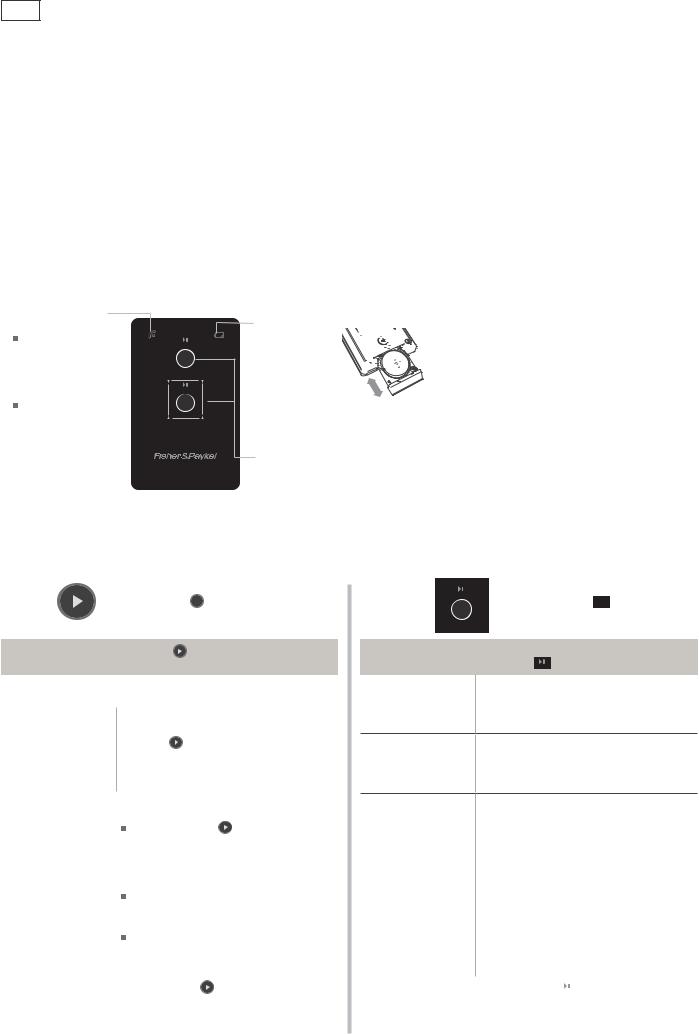
3.3.3 Wireless Remote ( some integrated models only)
Some markets have an integrated product available with a wireless badge control instead of a door badge, this ensures a seamless clean finish for the integrated door panel.
Signal indicator
A single flash indicates a successful signal to the dishwasher.
Multiple flashes indicate that the dishwasher cannot read the signal. The remote control may be out of range.
Double models only |
(operates lower drawer) |
‘Battery low’ indicator
When this 

 flashes, the


 battery needs to


 be replaced. Use


 a CR2032 battery,
 ensuring the
+ symbol faces up.
Control button(s)
Start/Pause Button
See section ‘Operating instructions’ for information.
3.3.4 Operation (some integrated models only)
You can operate the DishDrawer in two ways:
EITHER
by using the  button
on the drawer control panel
Start/resume wash |
1 |
Press . |
|
2 |
Close the drawer. The wash will start. |
||
|
|||
Pause wash |
You can only pause the wash with the |
||
remote. See opposite. |
|||
|
|||
1Pause the wash with the remote.
2Open the drawer, then press and
Cancel wash |
hold |
until you hear a |
||
quick double beep. |
||||
|
||||
|
Any water in the drawer will automatically |
|||
|
drain when you close it. |
|||
|
To delay the start of a wash by 1 to 12 |
|||
|
hours: |
|
|
|
|
Press and hold |
. Count the beeps |
||
|
as the dishwasher emits them (each |
|||
|
represents 1 more hour of delay) and |
|||
|
release the button when you have |
|||
Set Delay start |
reached the desired delay time. |
|||
|
The indicator of the selected wash |
|||
|
program will flash to show that Delay |
|||
|
start has been set. |
|||
|
The wash will start once the delay |
|||
|
time is over, provided the drawer is |
|||
|
closed. |
|
|
|
Cancel Delay start |
Press and hold |
until you hear a quick |
||
double beep and the indicator of the |
||||
|
selected wash program goes out. |
|||
OR
by using the  remote control button
Start/resume wash |
1 |
Close the drawer. |
||
2 |
Press |
. The wash will start. |
||
|
||||
|
|
|
|
|
Press  .
.
Pause wash After pausing a wash, wait for 3 beeps before opening the drawer. Forcing it open
in mid-cycle may cause damage or injury.
Press and hold  until you hear a quick
Cancel wash double beep.
Any water in the drawer will automatically drain.
You can only set Delay start on the drawer control panel. See opposite.
Set Delay start
|
Press and hold |
until you hear a quick |
Cancel Delay start |
double beep. |
|
|
|
|

16
3.3.5 Wireless Receiver |
|
|
|
The wireless badge receiver is built into a badge |
Part Label |
isolator housing and is a specific part number for the |
|
|
|
wireless badge models. This is identifed by the part |
|
number shown on the label. |
|
( for replacement refer section 9.30) |
|
NOTE: For each integrated product with the wireless |
|
badge, there is only one remote and one receiver, |
|
regardless of whether it is a single or double product. |
|
3.4 Motor
The motor is a fully electronically controlled 80V, 60w, 3 phase, 6 pole brushless DC motor, running on wash at between 2200 - 2800 rpm depending on the cycle selected, and at approximately 5000 rpm on drain.
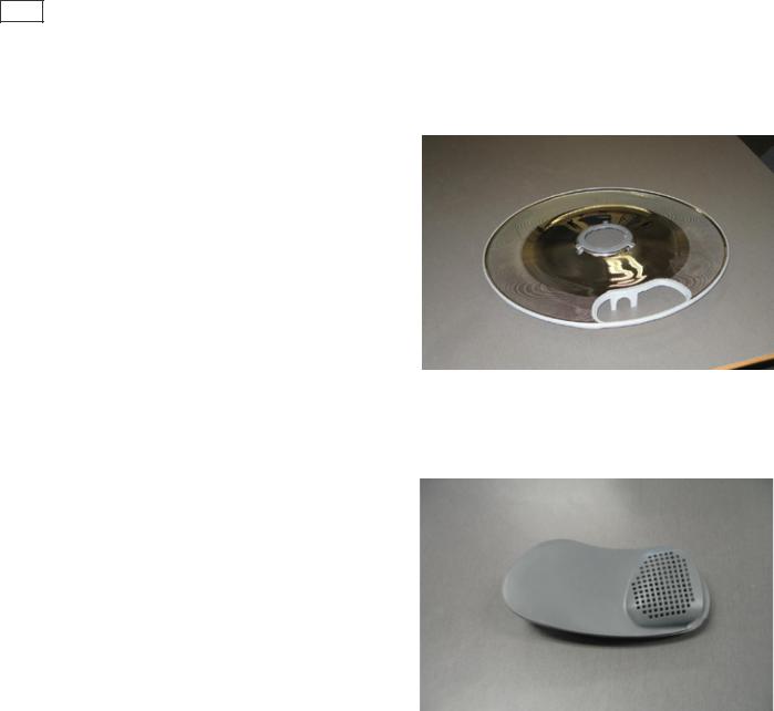
3.4.1 Rotor |
|
|
|
|
|
|
|
The rotor is a four-pole permanent magnet rotor with a |
|
|
|
|
|
|
|
|
|
|
|
|
Wash Impellor |
|
|
graphite bearing at each end of the vertical shaft. At the |
|
|
|
|
|
|
|
|
|
|
|
|
|
|
|
lower end of the rotor shaft is the drain impellor and at |
|
|
|
|
|
|
|
the upper end is the wash impellor. |
|
|
|
|
|
|
|
There is an O-ring around the top edge of the motor |
|
|
|
|
|
|
|
rotor which seals against the filterplate. |
|
|
|
|
|
|
|
|
Drain Impellor |
|
|
|
|
|
|
3.4.2 Spray Arm |
|
|
|
|
|
O-Ring Channel |
|
|
|
|
|
|
|
|
|
|
|
Air Valve |
|
|
|
|
|
|
|
|
|
|
|
|
|
The spray arm is shaped for most efficient water flow. |
|
|
|
|
|
|
|
The holes are positioned for best penetration into the |
|
|
|
|
|
|
|
wash load, with the water jets angled to ensure the |
|
|
|
|
|
|
|
spray arm rotates at the most efficient speed. There are |
|
|
|
|
|
|
|
2 sluicing jets located at the bottom of the spray arm to |
|
|
|
|
|
|
|
direct soils into the drain filter. |
|
|
|
|
|
|
|
The spray arms rotate at approx 11 rpm. |
|
|
|
|
|
|
|
Sluicing Jets
17
3.4.3 Filter Plate
The filter plate is a stainless steel disk positioned below the dish rack and spray arm and completely encompasses the base of the tub.
The drain filter has a rubber over mould around the edge to reduce soil re-depositing. Between the filter plate and rotor an o ring is also fitted to ensure a tight fit to reduce water leaks. These improvements will ensure a better wash performance.
The drain filter fits tightly into the filter plate, due to the rubber over mould around the edge.
3.4.4 Drain Filter
The tub has vanes that swirl the water around and over the filter plate. At the front of the tub, located as part of the filter plate, is the drain filter.
The drain filter is secured into the filter plate over mould which helps sealing.
Large soils collect in the drain filter and only smaller soil flows through its micro-mesh filter, eliminating re-depositing of soil during the wash.
The drain filter should be regularly checked and cleaned.

18
3.5 Lid System
The lid is a single piece of polymer plastic with a diaphragm/seal co-injection moulded into it. The centre of the lid can move relative to the seal. Each side of the lid is clipped into a yoke, which is in turn connected to a worm drive lid actuator assembly containing a small brushed DC 24 volt motor.
When the product is first plugged in and switched on at the wall, the lid motors are powered up to ensure that the lid is fully raised.
3.5.1 When Activated
At the beginning of the wash cycle, both lid motors are powered up to pull the lid down onto the tub flange in approx 2 -3 seconds. The lid remains down for the duration of the wash and is only lifted when the DishDrawer beeps to signal the end of the cycle, or if the cycle is paused to gain access to the tub.
3.5.2 During a Power Failure
If power to the DishDrawer™ fails with the lid down, the tub can still be forced open manually if access is required. It is very difficult however to close the tub again without raising the lid. The lid actuators can be wound up manually with the tub fully removed. Failure to raise the lid before closing the drawer can result in the lid seal being damaged.
3.6 Tub
The tub is the main cavity where all the wash activity occurs. The tub is a polymer plastic receptacle that houses the basket ware which includes adjustable cup racks and basket with fold down tines along with a wash pump and spray arm at the base. The tub also has guide vanes around its walls which direct falling water from the wash cycle in a clockwise direction around the filter plate. This clears the filter plate of food particles and washes them into the sump where they are trapped by the drain filter or pumped out during the drain cycle.
3.7Filling
3.7.1Water Inlet
The tub of the DishDrawer™ fills by a single water inlet hose. Hot water connection is recommended for USA and Japanese products, and cold water connection recommended for the Australasian, UK and European products. From the connection to the water supply tap in the kitchen, the inlet hose enters the cabinet of the dishwasher at the base, onto a dual water valve.
Each tub is supplied water independently via one of the dual valve coils and a fill hose that runs through a customised link assembly at the back of each tub and travels along the base of the tub under the wiring cover to the front. At the front of the tub, the fill hose connects to the water softener (if fitted) then to the detergent dispenser which directs water into the tub.
Depending on the market and cycle chosen, the product fills through the pre-rinse section of the dispenser for the pre-rinse cycles and secondly through the main wash section for all other cycles.
In a double product the controller allows only one inlet valve to operate at a time. This has been done to reduce EMC emissions, the top tub has priority.
Note: This restriction does not apply in diagnostic mode.
19
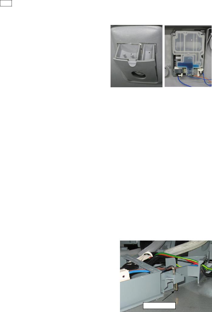
3.7.2 Dispensing Detergent and Rinse Aid
The dispenser is mounted in the front of the wash tub, and is held in place with 2 brackets and 6 torx screws.
The dispenser consists of two detergent chambers, the smaller one for the pre rinse and the larger one is the main wash bucket.
The detergent dispenser door is opened manually to fill the detergent bucket, and closed manually.
There is a positive displacement pump unit and storage tank incorporated within the dispenser to supply rinse aid.
The rinse aid volume is adjustable through the option adjustment mode (refer section 4). A glowing red light on the tank filler cap indicates an empty rinse aid tank.
3.7.3 Amount of Water
The tub fills with approximately 2.5 litres (0.8 US gallons) of water, almost level with the base of the spray arm. Once the level is reached, the wash pump (which is load sensed via the electronics) becomes primed and pumps the water through the spray arms causing them to rotate.
The load on the wash pump is continually monitored through the electronics, and the wash level adjusted if necessary.
If the wash pump looses prime, the electronics will top up the water level by opening the fill valve for approx 5 seconds, it will do this 3 times before carrying on regardless.
In low water pressure situations, the product will not reach a prime and may time out. In these cases the product will show a U1 fault code to the customer. (refer section 6).
3.7.4 Flood Protection
A flood sensor is mounted in the mains filter housing, and provides flood protection. If a flood is detected, the drain pump will run continually and an E1 fault code will be signalled to the customer.
Flood Sensor
20
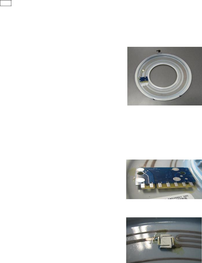
3.8Heating
3.8.1The Heating Element
The heating element is a porcelain enamelled steel plate, with a thick film resistive coating circuit printed onto the dry side. A
gravity thermal fuse is mounted on the heater plate in series with the heating element circuit.
A large dropping resistor is also printed onto the heater plate which forms part of the controllers power supply.
The element is clamped in place by a lock nut and supports the motor at the base of the tub.
3.8.2 Heating the Water
The heater plate is positioned beneath the filter plate. A flow through water heating system is created during the wash cycle by water flowing through the filter plate, over the surface of the element and into the wash pump.
3.8.3 Maintaining the Temperature
A printed circuit board with a temperature sensitive thermistor is mounted on the heater plate. The sensor parts are unservicable and if they fail a new heater plate is required.
3.8.4 Over Heat Protection
The heater plate is only activated during a wash cycle, and is not used in the dry cycle. The temperature is monitored by the
thermistor, and if a failure occurs with the electronic control of the heater plate, the over heat protection is effected by the thermal fuse on the heater plate.
The thermal fuse consists of a gravity fuse which is in series with the heater track. In an over heat situation the thermal fuse will melt and fall off the heater plate, disconnecting power to the element.
21
3.9 Motor and Heater Plate Locknuts
There are two locknuts holding the heater plate and motor housing assembly into the base of the tub, these form a watertight seal by compressing the two seals.
When reassembling the motor, it is important that a motor shim is placed between the inner locknut and the inner element seal.
The outer locknut has locations that hold the drain hose, fill hose and wiring loom in place.
3.10 Drain Cycle
The drain pump is a self-priming centrifugal pump that only pumps when the motor is rotating in the drain direction (anti-clockwise). It has a five bladed impellor pushed into a spline on the lower end of the rotor shaft.
The drain pump housing, which incorporates an inlet and outlet pipe, is welded to the motor housing, hence captivating the motor.
The inlet pipe plugs straight into the drain sump in the tub and is sealed there by a small ‘O’ ring.
The outlet pipe has a non-return flap valve to prevent soiled water returning to the tub.
The drain hose is an extruded blow moulded hose that is routed over the link assembly and exits out of the base of the product and is connected to a domestic drain.
The pump speed during the drain cycle is approx. 4200 rpm. In hardware output diagnostics test mode it is set to the same speed to aid diagnosing drain problems.
On a double product, the drain motor on the tub which is not being used will run for a short time during the final drain phase of a wash cycle. This is to remove any drain water that may have back flowed in to the unused tub.
This concurrent drain will not happen if the unused tub is open. If the user presses the power button after water has been placed in the tub, the product will initiate a “power off” drain and empty the tub.
Non Return Valve

22
3.11 Filter Plate
The filter plate is a stainless steel disk positioned below the dish rack and spray arm and completely encompasses the base of the tub.
The drain filter has a rubber over mould around the edge to reduce soil re-depositing. Between the filter plate and rotor an o ring is also fitted to ensure a tight fit to reduce water leaks. These improvements will ensure a better wash performance.
The drain filter fits tightly into the filter plate, due to the rubber over mould around the edge.
3.11.1 The Filter System
The tub has vanes that swirl the water around and over the filter plate. At the front of the tub, located as part of the filter plate, is the drain filter.
The drain filter is secured into the filter plate over mould which helps sealing.
Large soils collect in the drain filter and only smaller soil flows through its micro-mesh filter, eliminating redepositing of soil during the wash.
The drain filter should be regularly checked and cleaned.
3.11.2 Removing and Cleaning the Drain Filter and Filter Plate
The drain filter can be emptied with the dish rack in place by removing the cutlery basket and opening the plastic section of the dish rack.
To remove the drain filter pull upwards to release, clean under running water, when refitting ensure the drain filter sits flush with the filter plate.
The filter plate is removable for cleaning by removing the dish rack and spray arm and unlocking the locknut by turning it anti-clockwise. Turning it too far will also release the rotor and may allow it to be lifted out with the filter plate.
Clean under running water. When refitting ensure the 3 inner locking pins on the lock ring are securely fitted.
23
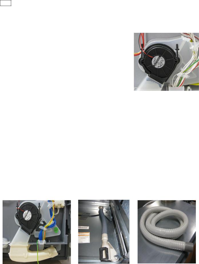
3.12 Drying Cycle
Immediately after water from the final hot rinse has been drained from the tub, the drying cycle begins.
The drying fan draws air through the vent in the rear into the tub where it absorbs water from the dish load. The moisture-laden air is then mixed with a larger quantity of ambient air (drawn from the kitchen), to minimise the amount of vapour visible when air is exiting from the bottom of the drawer front.
A flap valve is located in the fan housing. This is closed to prevent moist air from entering the space behind the door panel during the wash, reducing the possibility of damage to the controller and LCD. It opens whenever the fan is running.
The fan runs continuously during the drying cycle for various times depending on the program selected, and will restart if the tub is opened and closed again. After the wash program is complete (when it beeps and the LCD shows 00), the lid drives up, and the fan continues to run for anything up to 120 minutes depending on the program, but will not restart if the tub is opened or if a button is pressed.
NOTE: The vented integrated single product does have a dwell/pause phase before commencing the fan, this is to allow the water to condense back onto the tub.
3.12.1 Integrated Single Drawer Venting (some models only)
Some single integrated models (depending on market) have a vent which runs internally inside the product and vents the air through the rear of the product via an exhaust pipe. This pipe is connected to the product at an elbow and will vent the air out through the joinery kickstrip.
This venting allows a longer door to be fitted to the customers joinery, reducing the required panel gap at the front of the product.
 Loading...