


 S SECURITY SYSTEM
USER’S MANUAL
Model
DVRA0405/DVRA0805/DVRA0810/DVRA1610

INTRODUCTION
THANK YOU
Welcome
Thank you for choosing First Alert for your security needs!
For more than half a century, First Alert has made the home-safety and security products that make your job easier. Our products are built to the highest standard which has earned us a leadership role in the home-safety and security product categories. We are committed to serving our customers, from the professionals who install our products, to the families and businesses who count on them. First Alert has been helping families and businesses stay safe for over 50 years. By having a First Alert Security System, you’re taking the first step in protecting your home or business from damage or theft. We’re watching, even when you’re not.
This manual is written for the SmartBridge™ DVRA0405/DVRA0805/DVRA0810/DVRA1610 DVRs. It was accurate at the time it was completed. However, because of our ongoing effort to constantly improve our products, additional features and functions may have been added since that time and on-screen displays may change. We encourage you to visit our website at www.firstalert.com to check for the latest manuals (English and Spanish), firmware updates, downloads, other security camera products and announcements. You’ll find this product line under Home Security >> Security Cameras >>Wired Cameras.
© 2012 BRK Brands, Inc. All rights reserved. Distributed by BRK Brands, Inc., Aurora, Illinois 60504. BRK Brands, Inc. is a subsidiary of Jarden Corporation (NYSE: JAH). First Alert® and SmartBridge™ are registered trademarks of the First Alert Trust. Due to continuing product development, the product inside the packaging may look slightly different than the one on the package. To obtain warranty service, contact the Consumer Affairs Division at 1-800-323-9005, Monday through Friday, 7:30 a.m. - 5 p.m., Central Standard Time.
Made in China
Page 2

INTRODUCTION
KEY PRODUCT FEATURES
Main Description
Eight channel H.264 digital video recorder with Internet remote surveillance, motion detection, PTZ and alarm control suitable for applications such as high-end residential - new or remodel, light commercial, small business/retail, small warehouse or small grocery.
Product Features
•Auto IP connection capability
•H.264 Compression & Virus free Linux O/S
•Record, playback, mobile phone live view, backup, control, & remote access
•500 GB or 1 TB SATA hard drive installed
•Supports smart phone live view
•User-friendly interface: DVR capable of providing 16 bit true color, semi-transparent GUI with notes for selected menu items.
•Advanced motion detection activated recording
•24/7 Scheduled Recording
•Network monitoring through internet access
•Supports USB or external DVD backup
•Hi-speed backup/upgrade/record via USB2.0
•PTZ camera control
Page 3

INTRODUCTION
TABLE OF CONTENTS
Section |
Description |
Page # |
|
|
|
1 |
Introduction |
2-5 |
|
|
|
2 |
Safety |
6 |
|
Product Overview |
7 |
|
|
|
|
What is in the Box |
7 |
|
|
|
|
DVR Controls |
8-9 |
|
|
|
3 |
Front Panel |
8 |
Back Panel |
9 |
|
|
Remote Control |
10 |
|
|
|
|
Mouse and Virtual Keypad |
11 |
|
|
|
|
Camera Power Connections |
12 |
|
|
|
|
Connecting Devices |
12 |
|
|
|
|
Initial Setup - System Operation |
13 |
|
System Start Up |
13 |
|
|
|
|
Power On/Off |
13 |
|
|
|
4 |
Main Menu Access (Quick Access Menu) |
14 |
|
|
|
Password Setup and User Permissions |
14-15 |
|
|
Language |
15 |
|
Camera Display Setup |
16 |
|
|
|
|
Date and Time |
17 |
|
|
|
|
Display, Video/Audio |
17 |
|
|
|
|
Basic Operation |
18 |
|
Recording |
18 |
|
|
|
|
Configure Recording Options |
18 |
|
|
|
|
Recording Schedule (Timer Recording) |
18 |
|
|
|
|
Recording Schedule (TIMER RECORD) Example |
18 |
5 |
Motion Detect Setup |
19 |
Playback |
20 |
|
|
|
|
|
Live Snapshot |
20 |
|
|
|
|
Playback and Record Search |
21 |
|
|
|
|
On-Screen Playback Controls |
21 |
|
|
|
|
File List |
21 |
|
Backup |
21 |
|
HDD Management |
21-22 |
Page 4

INTRODUCTION
TABLE OF CONTENTS
Section Description |
Page # |
|
|
|
Advanced Operation |
22 |
|
|
Alarm |
22-23 |
|
|
|
|
|
|
Alarm In Setup |
22-23 |
|
|
|
|
|
|
System Info and System Update |
24 |
|
|
|
|
|
6 |
System Maintain |
24 |
|
Upgrade Firmware |
24 |
||
|
PTZ Setup and Control |
25-26 |
|
|
|
|
|
|
Step 1: Connect your PTZ Camera to this DVR |
25 |
|
|
|
|
|
|
Step 2: Configure PTZ Communication Settings |
25 |
|
|
|
|
|
|
Step 3: Configure the Operation and Control of your PTZ Camera(s) |
25 |
|
|
|
|
|
|
Step 4: Configure the CRUISE SETTING of your PTZ Camera |
26 |
|
|
Remote Access |
27 |
|
|
|
|
|
|
Network Setup for Remote Access |
27-31 |
|
|
|
|
|
|
Record External |
32 |
|
|
|
|
|
7 |
Playback External |
33-34 |
|
Settings |
35 |
||
|
|||
|
Advanced Settings |
36 |
|
|
|
|
|
|
Pan Tilt Zoom |
37 |
|
|
|
|
|
|
Setting Up Groups |
37-38 |
|
|
|
|
|
|
Remote Configuration |
39-40 |
|
|
Appendix |
41 |
|
|
|
|
|
|
Hard Drive Removal and Installation |
41 |
|
|
|
|
|
8 |
Specifications |
42 |
|
|
|
||
FAQ’s (Frequently Asked Questions) |
43-44 |
||
|
|||
|
Troubleshooting |
45 |
|
|
Warranty |
46 |
Page 5
SAFETY
CAUTION STATEMENTS
Safety Precautions
•Do not drop, puncture, or disassemble the cameras or DVR.
•Do not tug on the power adapter. Use the plug to remove it from the wall.
•Do not expose the cameras or DVR to high temperatures.
•For your own safety, avoid using the DVR when there is a storm or lightning in your area.
•Use the cameras and DVR with care. Avoid pressing hard on the cameras or DVR body.
•Do not use power cable if it is damaged or crushed.
Safety Precautions
Instructions for Use
•Always purchase the correct size and grade of battery most suitable for the intended use.
•Replace all batteries of a set at the same time.
•Clean the battery contacts and also those of the device prior to battery installation.
•Ensure the batteries are installed correctly with regard to polarity (+ and -).
•Remove batteries from equipment that is not to be used for an extended period of time.
•Remove used batteries promptly.
FCC Compliance
FCC Compliance Class B Digital Device
This equipment has been tested and found to comply with the limits for a Class B digital device, pursuant to Part 15 of the FCC rules. These limits are designed to provide reasonable protection against harmful interference in a residential installation. This equipment generates, uses and can radiate radio frequency energy and, if not installed and used in accordance with the instructions, may cause harmful interference to radio communications.
However, there is no guarantee that the interference will not occur in a particular installation. If this equipment does cause harmful interference to radio or television reception, which can be determined by turning the equipment off and on, the user is encouraged to try to correct the interference by one or more of the following measures:
•Reorient or relocate the receiving antenna.
•Increase the separation between the equipment and receiver.
•Connect the equipment into an outlet on a circuit different from that of the receiver.
•Consult the dealer or an experienced radio or TV technician for help.
Notice: Only peripherals complying with FCC class B limits may be attached to this equipment. Operation with non-compliant peripherals or peripherals not recommended by First Alert / BRK Brands, Inc. is likely to result in interference to radio and TV reception. Changes or modifications to the product, not expressly approved by First Alert / BRK Brands, Inc., could void the user’s authority to operate the equipment.
Important: The information shown in the FCC Declaration of Conformity paragraph below is a requirement of the FCC and is intended to supply you with information regarding the FCC approval of this device. The phone number listed below is for FCC related questions only and not intended for questions regarding the connection or operation for this device.
FCC Declaration of Conformity for devices with the FCC logo. Responsible Party: First Alert / BRK Brands, Inc., 3901 Liberty Street Rd., Aurora, IL. 605048122. Telephone: (630) 851 - 7330. Product / Model: DVRA0405, DVRA0805, DVRA0810, and DVRA1610. We, First Alert / BRK Brands, Inc. declare under our sole responsibility that the device to which this declaration relates: Complies with Part 15 of the FCC Rules. Operation is subject to the following two conditions: (1) this device may not cause harmful interference, and (2) this device must accept any interference received, including interference that may cause undesired operation.
FCC Certification (if applicable)
This device contains a radio transmitter. Accordingly, it has been certified as compliant with 47 CFR Part 15 of the FCC Rules for intentional radiators. Products that contain a radio transmitter are labeled with an FCC ID.
Fire and Electric Shock Hazard Statement
CAUTION
RISK OF ELECTRIC SHOCK
CAUTION: TO REDUCE THE RISK OF ELECTRIC SHOCK. UNPLUG ALL POWER SOURCES, INCLUDING CAMERAS FROM THE DVR BEFORE REMOVING COVER. FAILURE TO DO SO CAN RESULT IN DAMAGE TO THE DVR OR ITS COMPONENTS AS WELL AS INJURY OR DEATH.
The lightning flash with arrowhead symbol, within an equilateral triangle, is intended to alert the user to the presence of un-insulated “dangerous voltage” within the product’s enclosure that may be of sufficient magnitude to constitute a risk of electric shock.
The exclamation point within an equilateral triangle, is intended to alert the user to the presence of important operating and maintenance (servicing) instructions in the literature accompanying the appliance.
WARNING: TO PREVENT FIRE OR SHOCK HAZARD, DO NOT EXPOSE THIS DVR UNIT TO RAIN OR MOISTURE
CAUTION: TO PREVENT ELECTRIC SHOCK, MATCH WIDE BLADE OF THE PLUG TO THE WIDE SLOT AND FULLY INSERT
Caution!
When working with electrostatic sensitive devices such as hard disk or DVR unit, make sure you use a static-free workstation. Any electrostatic energy coming in contact with the hard
disk or DVR can damage it permanently.
Disposal
These symbols indicate that it is prohibited to dispose of these batteries in the household waste. Take spent batteries that can no longer be charged to the designated collection points in your community.
Page 6

PRODUCT OVERVIEW
PACKAGE CONTENTS
What,s in the Box*
H.264 8 channel Digital DVR with 500 GB or 1 TB Hard Drive
DVRA0405/DVRA0805: 500 GB
DVRA0810/DVRA1610: 1TB
ENGLISH |
DVR QUICK START GUIDE |
|
Step 2: Connecting the Cameras / DVR |
Step 4: Downloading the SmartBridge Software |
|||||||||||
|
|
|
|
|
|
|
Connect the BNC & power from camera with BNC power cable using the side labeled |
Insert install CD into CD Rom Drive Double click SmartBridge.exe or let |
|||||||
|
|
|
|
|
|
|
"Camera Side” |
|
|
|
|
CDRom run automatically. |
|||
|
|
|
|
|
|
|
Using other side of BNC power cable connect BNC to BNC video input on DVR |
Install SmartBridge Software. |
|||||||
|
|
|
|
|
|
|
Connect power cable to one of the multi power splitter ends |
On your computer desktop, Double click installed Smartbridge Software Icon. |
|||||||
|
Product Contents |
|
|
|
|
Plug (red) connector on power splitter to 12V DC input on DVR |
Select the Connect Tab. Enter Auto ID DVR Code (On DVR system, right click and |
||||||||
|
|
|
|
|
Plug DVR power supply into wall outlet |
select “Net Status” to obtain Auto ID DVR Code). Password is default 123. Select |
|||||||||
|
|
|
|
|
|
|
|
|
|
|
|
|
Login to start viewing your Smartbridge security system remotely. |
||
|
|
|
|
|
|
|
|
|
|
|
|
|
1 |
|
|
|
|
|
|
|
BNC VIDEO & DC POWER CABLE |
|
|
|
|
|
|
|
|
|
|
|
|
DVR |
|
2 |
|
4 |
|
|
|
|
|
|
|||
|
|
CAMERA(S) |
POWER SUPPLY |
|
|
|
|
|
|
|
|
||||
|
|
|
|
3 |
|
5 |
|
|
|
||||||
|
|
|
|
|
DVR & CAMERAS |
|
|
|
|
|
|
|
2 |
|
|
|
|
REMOTE CONTROL & |
|
|
|
|
|
|
|
|
|
|
|
||
|
|
USB 2.0 MOUSE |
RJ45 ETHERNET CABLE |
|
|
|
|
|
|
|
|
|
|
||
|
|
|
|
|
|
|
Step 3: Connecting your Mouse and Ethernet Cable |
|
|
|
|||||
|
|
|
|
|
POWER SPLITTER FOR |
|
Connect the USB mouse to the bottom USB slot on the back |
4 |
|
|
|||||
|
|
|
|
|
|
Connect the Ethernet cable to the back of the DVR labeled either NET or RJ45 |
|
|
|
||||||
|
|
STICKERS |
DVR AND CAMERAS |
|
Connect the other end of the cable directly to your router, modem or high speed |
|
|
|
|||||||
|
|
|
|
|
|
|
internet connection input |
|
|
|
|
3 |
|
|
|
|
|
|
|
|
|
|
Note: Please consult the networking section of your manual to configure the DVR for |
|
|
|
|||||
|
Step 1: Connect the DVR to your Monitor or TV |
|
|
remote viewing. |
|
|
|
|
|
|
|
||||
|
(Monitor Option) |
|
|
|
|
|
|
|
|
|
|
|
|||
|
Connect a VGA cord (not included) from your monitor to the VGA Output port on the back of your DVR. |
|
|
|
|
|
|
|
|
|
|
||||
|
(TV Option) |
|
|
|
|
|
|
|
3 |
|
|
|
|
|
|
|
Connect the end of the BNC-RCA (BNC SIDE ONLY) cable to the back of the |
|
|
|
|
|
|
|
|
|
|
||||
|
DVR labeled “Video Output” |
|
2 |
|
|
|
|
|
|
|
|||||
|
Connect the BNC-RCA (RCA SIDE ONLY) cable to an open video (yellow RCA) input on your TV/Monitor |
|
|
|
|
Go to firstalert.com and search for model # to find complete instruction manual of |
|||||||||
|
(note the input name or number) |
|
|
|
|
|
|
|
|
||||||
|
Turn on your TV and select the appropriate input (noted above) |
|
|
|
|
|
|
|
|
your First Alert DVR. |
|||||
1
www.firstalert.com
Quick Install Guide
Power Supply
for DVR
|
|
|
|
|
|
|
|
|
|
|
|
|
|
|
|
|
WARNING |
|
|
|
|
|
|
|
THESE PREMISES ARE UNDER |
||||
|
|
|
|
|
24 HOUR VIDEO SURVEILLANCE |
||||
|
|
|
|
|
|
|
PROTECTED BY |
||
|
|
|
|
|
|
|
|
|
|
|
|
|
|
|
|
|
|
|
|
Installation |
|
|
|
|
|
3 Window |
|||
|
|
RJ45 Ethernet Cable |
|
|
|||||
|
Software |
|
Warning Decals |
||||||
|
|
|
|
||||||
Remote Control |
USB 2.0 Mouse |
Page 7
PRODUCT OVERVIEW
DVR CONTROLS
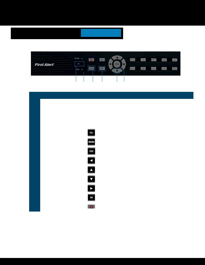
Front Panel
|
2 |
|
12 |
|
4 |
|
7 |
|
8 |
|
10 |
|
||||||||
|
|
|
|
|
|
|
|
|
|
|
|
|
|
|
|
|
|
|
|
|
|
|
|
|
|
|
|
|
|
|
|
|
|
|
|
|
|
|
|
|
|
|
|
|
|
|
|
|
|
|
|
|
|
|
|
|
|
|
|
|
|
|
|
|
|
|
|
|
|
|
|
|
|
|
|
|
|
|
|
|
|
|
|
|
|
|
|
|
|
|
|
|
|
|
|
|
|
|
|
|
|
|
|
|
|
|
|
|
|
|
|
|
|
|
|
|
|
|
|
|
|
|
|
|
|
|
|
|
|
|
|
|
|
|
|
|
|
|
|
|
|
|
|
|
|
|
|
|
|
|
|
|
|
|
|
|
|
|
|
|
|
|
|
|
|
|
|
|
|
|
|
|
|
|
|
|
|
|
|
|
|
|
|
|
|
|
|
|
|
|
|
|
|
|
|
|
|
|
|
|
|
|
|
|
|
|
|
|
|
|
|
1 |
|
3 |
|
5 |
|
|
6 |
|
9 |
|
11 |
|
|
|
|
|
|
|
|
|
|
|
|
|
|
|
|
|
|
|
|
|
|
|
|
|
|
|
|
|
|
|
Item |
Function |
Control |
Description |
|
|
|||||||||
|
|
|
|
|
|
|
|
|
|
|
|
|
|
|
1 |
(1) IR remote receiver |
|
|
|
|
|
Direct remote towards this position when using DVR |
|||||||
|
|
|
|
|
|
|
|
|
|
|
|
|
|
|
2 |
Power indicator light |
|
|
|
|
|
A green light indicates power is on |
|||||||
|
|
|
|
|
|
|
|
|
|
|
|
|
|
|
3 |
Record indicator light |
|
|
|
|
|
A green flashing light indicates recording |
|||||||
|
|
|
|
|
|
|
|
|
|
|
|
|
|
|
|
Buttons 1-4(8)(16) |
|
|
|
|
|
Camera Selection |
|||||||
|
|
|
|
|
|
|
|
|
|
|
|
|
|
|
4 |
10+ |
|
|
|
|
|
|
|
Press for camera selection of channels 10-16 (on 16 channel DVR only) |
|||||
|
|
|
|
|
|
|
|
|
|
|
|
|
|
|
5 |
Menu |
|
|
|
|
|
Enter menu setup |
|||||||
|
|
|
|
|
|
|
|
|
|
|
|
|
|
|
6 |
ESC |
|
|
|
|
|
Brings system previous selection |
|||||||
|
|
|
|
|
|
|
|
|
|
|
|
|
|
|
7 |
Left |
|
|
|
|
|
In menu mode: moves to highlight next section |
|||||||
|
|
|
|
|
|
|
|
|
|
|
|
|
|
|
8 |
Up |
|
|
|
|
|
In live mode: rotates between single , quad, eight or nine camera screen |
|||||||
|
|
|
|
|
|
|
|
|
|
|
|
|
|
|
9 |
Down |
|
|
|
|
|
In live mode: rotates between single , quad, eight or nine camera screen |
|||||||
|
|
|
|
|
|
|
|
|
|
|
|
|
|
|
10 |
Right |
|
|
|
|
|
In menu mode: moves to highlight previous section |
|||||||
|
|
|
|
|
|
|
|
|
|
|
|
|
|
|
11 |
OK |
|
|
|
|
|
Press to make selection |
|||||||
|
|
|
|
|
|
|
|
|
|
|
|
|
|
|
12 |
Sleep |
|
|
|
|
|
On 16 Channel DVR only |
|||||||
|
|
|
|
|
|
|
|
|
|
|
|
|
|
|
Page 8
PRODUCT OVERVIEW
DVR CONTROLS
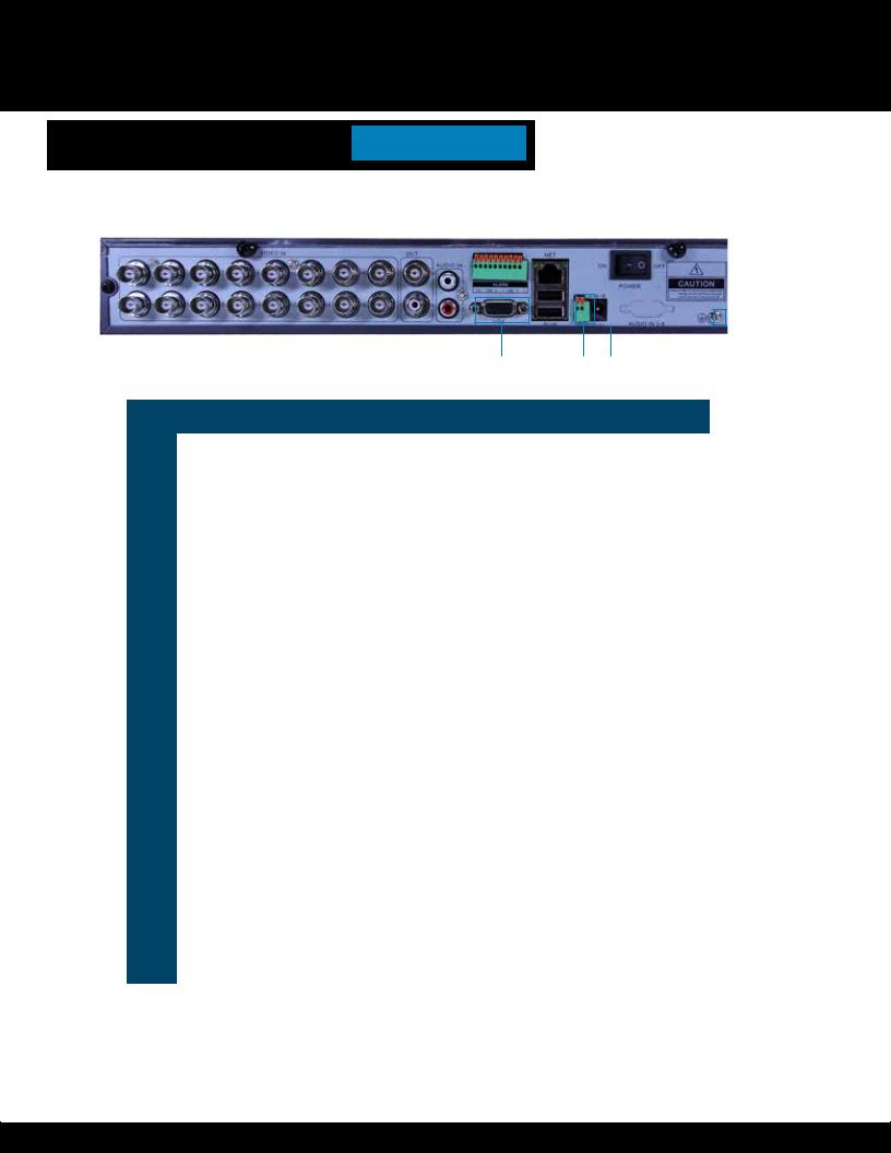
Back Panel
|
9 |
|
|
10 |
|
8 |
|
|
1 |
|
|
4 |
|
6 |
|
|
|
||||||||||
|
|
|
|
|
|
|
|
|
|
|
|
|
|
|
|
|
|
|
|
|
|
|
|
|
|
|
|
|
|
|
|
|
|
|
|
|
|
|
|
|
|
|
|
|
|
|
|
|
|
|
|
|
|
|
|
|
|
|
|
|
|
|
|
|
|
|
|
|
|
|
|
|
|
|
|
|
|
|
|
|
|
|
|
|
|
|
|
|
|
|
|
|
|
|
|
|
|
|
|
|
|
|
|
|
|
|
|
|
|
|
|
|
|
|
|
|
|
|
|
|
|
|
|
|
|
|
|
|
|
|
|
|
|
|
|
|
|
|
|
|
|
|
|
|
|
|
|
|
|
|
|
|
|
|
|
|
|
|
|
|
|
|
|
|
|
|
|
|
|
|
|
|
|
|
|
|
|
|
|
|
|
|
|
|
|
|
|
|
|
|
|
|
|
|
|
|
|
|
|
|
|
|
|
|
|
|
|
|
|
|
|
|
|
|
|
|
|
|
|
|
|
|
|
|
|
|
|
|
|
|
|
|
|
|
|
|
|
|
|
|
|
|
|
|
|
|
|
|
|
|
|
|
|
|
|
|
|
|
|
|
|
|
|
|
|
|
|
|
|
|
|
|
|
|
|
|
|
|
|
|
|
|
11 |
|
2 |
|
3 |
|
|
5 |
|
7 |
|
12 |
|
|
|
|
|
|
|
|
|
|
|
|
|
|
|
|
|
|
|
|
|
|
|
|
|
|
|
|
|
|
Item |
Function |
Description |
|
|
|
|
|
|
|
|
|
|
||
|
|
|
|
|
|
|
|
|
|
|
|
|
|
|
1 |
Alarm |
4 alarm inputs; 1 alarm output |
|
|
|
|
|
|
|
|
|
|
||
|
|
|
|
|
|
|
|
|
|
|
|
|
|
|
2 |
VGA Output |
For connecting to VGA monitor |
|
|
|
|
|
|
|
|
|
|
||
|
|
|
|
|
|
|
|
|
|
|
|
|
|
|
3 |
USB/Mouse |
Use Lower USB port for mouse connection; Use Upper USB port for USB |
|
|||||||||||
flashdrive or backup |
|
|
|
|
|
|
|
|
|
|
||||
|
|
|
|
|
|
|
|
|
|
|
|
|||
|
|
|
|
|
|
|
|
|
|
|
|
|
|
|
4 |
NET |
For connecting RJ45 ethernet cable to PC or router |
|
|
|
|
|
|||||||
|
|
|
|
|
|
|
|
|
|
|
|
|
|
|
5 |
RS485 |
For connecting PTZ cameras |
|
|
|
|
|
|
|
|
|
|
||
|
|
|
|
|
|
|
|
|
|
|
|
|
|
|
6 |
Power Switch |
Power On/Off |
|
|
|
|
|
|
|
|
|
|
||
|
|
|
|
|
|
|
|
|
|
|
|
|
|
|
7 |
Power Supply |
For connection to power cord +12V DC |
|
|
|
|
|
|
|
|
||||
|
|
|
|
|
|
|
|
|
|
|
|
|
|
|
8 |
Audio Input |
For connecting audio signal from audio capable cameras or self powered |
|
|||||||||||
microphones (RCA jacks) |
|
|
|
|
|
|
|
|
|
|
||||
|
|
|
|
|
|
|
|
|
|
|
|
|||
|
|
|
|
|
|
|
|
|
|
|
|
|
|
|
9 |
Video Input |
For connecting video signal from cameras (BNC) |
|
|
|
|
|
|||||||
|
|
|
|
|
|
|
|
|
|
|
|
|
|
|
10 |
BNC Output |
For connecting to a BNC monitor |
|
|
|
|
|
|
|
|
|
|
||
|
|
|
|
|
|
|
|
|
|
|
|
|
|
|
11 |
Audio Output |
For connecting audio signal to amplified speakers (RCA jacks) |
|
|||||||||||
|
|
|
|
|
|
|
|
|
|
|
|
|
|
|
12 |
Ground |
Ground Connection |
|
|
|
|
|
|
|
|
|
|
||
|
|
|
|
|
|
|
|
|
|
|
|
|
|
|
Page 9
PRODUCT OVERVIEW
REMOTE CONTROL
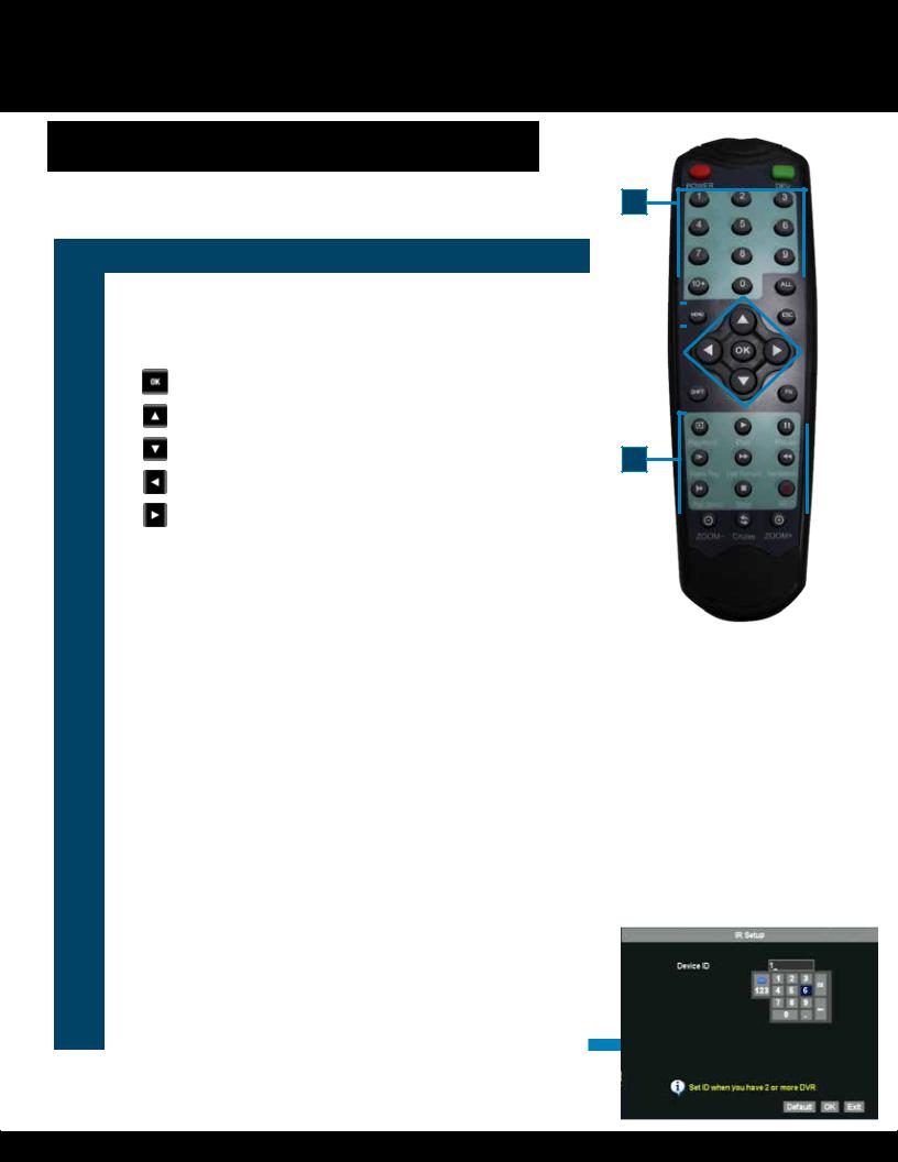
Remote Control
Remote Control Operation
The remote control is the secondary input device for navigating the system’s interface. In device operation, the MENU key has the same function as “left click” of the mouse.
Item |
Function |
Description |
|
|
|
|
|
1 |
Power |
Click power for about 3-5 seconds to shut down the DVR. |
|
|
|
|
|
2 |
Numeric |
Press to Select channel to view; use to input numerical information in |
|
Buttons |
appropriate screens |
||
|
|||
|
Navigation Buttons |
||
|
|
|
|
|
|
Press to make selection |
|
|
|
|
|
|
|
Press to cursor up; in PTZ mode, press to pan camera up |
|
3 |
|
|
|
|
Press to move cursor down; in PTZ mode, press to pan camera down |
||
|
|
||
|
|
|
|
|
|
Press to move cursor left; in PTZ mode, press to pan camera left |
|
|
|
|
|
|
|
Press to move cursor right; in PTZ mode, press to pan camera right |
|
|
|
|
|
|
PLAYBACK CONTROLs |
||
|
Playback |
Search Recordings |
|
|
Play |
Play Recording (resumes after pause) |
|
|
|
|
|
|
Pause |
Pause Playback in recording mode |
|
|
|
|
|
4 |
Frame |
Playback by frame |
|
|
|
||
Fast Forward |
Press to fast forward |
||
|
|||
|
|
|
|
|
Fast Backward |
Press to fast backward |
|
|
|
|
|
|
Play Slowly |
Press to play video slowly |
|
|
|
|
|
|
Stop |
Press to stop playback |
|
|
|
|
|
|
Record |
Press to record video (allows to select any or all cameras) |
|
|
|
|
|
5 |
Zoom – |
(For PTZ cameras only) Press to zoom out |
|
|
|
|
|
6 |
Zoom + |
(For PTZ cameras only) Press to zoom in |
|
|
|
|
|
7 |
Menu |
Quick access menu |
|
|
|
|
|
8 |
All |
Displays all cameras |
|
|
|
|
|
9 |
10+ |
Press for camera selection of channels 10-16 |
|
|
|
|
|
10 |
ESC |
Exits Page/Command |
|
|
|
|
|
11 |
DEV |
Allows setting the remote default ID |
|
(To use the remote for |
|||
|
more than one DVR) |
|
|
Any button not identified is not used.
1 |
|
|
|
|
|
11 |
|
|
|||||
|
|
|
|
|
|
|
2
9 |
|
|
|
|
|
|
|
|
|
|
|
|
|
|
|
|
|
|
|
8 |
|
|
|
|
|
|
|
|
|
|
||
|
|
|
|
|
|
|||||
7 |
|
|
|
|
|
|
|
|
|
|
|
|
|
|
|
|
|
|
|
10 |
|
|
|
|
|
|
|
|
|
|
||
|
|
|
|
|
|
|
|
|
|
|
|
|
|
|
|
|
|
|
|
|
|
3 |
|
|
|
|
|
|
|
|
|
|
|
|
|
|
|
|
|
|
|
|
|
|
|
|
|
|
|
|
|
|
|
|
|
|
|
|
|
|
|
|
|
|
|
4
5 |
|
|
|
|
|
|
|
6 |
|
|
|
|
|||||
|
|
|
|
|
|
|
|
|
Directions for Installing/ Changing Batteries
1.Open battery compartment on back of Remote and insert (2) Alkaline
AAA batteries (provided.)
2.Ensure all batteries are installed correctly with regard to polarity (+ and -.)
3.Remove batteries from Remote if it is not to be used for an extended period of time.
4.Remove used batteries promptly and replace all batteries of a set at the same time.
5.Always purchase the correct size and grade of battery most suitable for intended use.
Page 10
PRODUCT OVERVIEW
MOUSE AND VIRTUAL KEYPAD
Mouse Controls
Mouse Operation with this DVR
The mouse is the primary input device for navigating system menus. NOTE: Unless otherwise noted, all system functions described
in this manual are achieved through mouse input.
To use a mouse with the system:
Connect a USB mouse to the USB MOUSE port on back panel of the system. NOTE: Only the USB 2.0 port on the back panel (Upper USB port)
is designed for data backup to a USB flash drive. Do not connect a USB flash drive to the USB MOUSE port. (Lower USB port)
Use the mouse buttons to perform the following:
1Left-Button:
•Click to select a menu option
•During live viewing in split-screen double-click on a channel to view the selected channel in full-screen
•Double-click the channel again to return to split-screen view
|
• |
Selecting letter or number on the virtual keypad |
|
|
|
|
DVR REAR |
||
|
|
|
|
|
|
Connect Mouse & |
|||
|
Right-Button: |
|
|
|
|
USB Drive |
|||
2 |
|
|
|
||||||
|
|
|
|
|
|
|
|||
|
• |
Click to open the Quick Access Menu |
|
|
|
|
|
|
|
|
|
|
|
|
|
|
|
||
|
• |
Exits any window |
|
|
|
|
|
|
Mouse Button |
|
• |
Exits any menu or re-opens previous menu |
|
|
|
|
2 |
||
|
|
|
3 |
|
|
|
Operation |
||
|
|
|
|
|
|
|
|||
|
|
|
|
|
|
||||
|
Scroll-Wheel: |
|
|
|
|
|
|
|
|
3 |
|
|
|
|
|
|
|
||
|
• |
No function |
1 |
|
|
|
|
|
|
|
|
|
|
|
|||||
|
|
|
|
|
|
|
|
||
Virtual Keypad
Virtual Keypad
To enter text or numerical data, the system uses a virtual keypad. In fields where letters or numbers can be entered, you can switch between various formats – numbers, upper case (ABC) and lower case (abc). Note you can access all numbers when in the “Letters” virtual keypads. See below.
|
|
|
|
|
Numbers |
Letters-Lowercase |
Letters-Uppercase |
Page 11

PRODUCT OVERVIEW
CAMERA AND POWER CONNECTIONS
Installing Cameras
Mounting Cameras and Running Cable
Select the position for the camera and secure the camera stand. Screw the camera onto the stand. Adjust camera to the proper view angle. Make sure the lens is upright relative to the subject. Tighten the thumb bolt. First Alert cameras can be either ceiling or wall mounted by simply reversing the camera stand mounting. See “Camera Orientation” Info box. Holes are provided on both the top and bottom of the camera housing to accommodate most mounting requirements. Run cable from camera to DVR location. See Information box below on “Longer Cable Runs”.
Camera Orientation
It’s important the camera is mounted correctly to ensure the image is not upside down as the camera lens can only be positioned one way.
Longer Cable Runs
|
Longer cable runs may require an upgrade to |
|
RG59 Coax cable. First Alert kits ship with eco- |
|
nomical AV cable that is designed to work well up |
|
to the length of cable provided, usually around |
|
60 feet. If longer distances between camera and |
|
DVR are required, you will need to upgrade to RG59 Coax cable. We |
|
provide several lengths up to 300 feet. In addition, if you need to run |
Camera - Wall Mounted |
cable for in-wall installations, then you may require fire rated cable, |
FT-4/CMR UL approved for in-wall installations. |
Step 2... Connecting Devices
Follow this diagram to make device connections. Note, some devices are not included with this kit. See “What’s in the Box” for included devices.
VGA to PC Monitor or TV BNC to Security Camera Monitor
(Not included)
Back Panel
Connect Mouse &
USB Drive
Smartphone
through Mobile
Internet Setup


 (Smartphone Not
included)
Video to DVR
Channels 1-8
RCA Audio Out to Powered Speakers
(Not included) RJ45 Ethernet to Router and Internet
PTZ & Alarm Connections (Cameras not included)
|
|
|
|
|
|
|
|
|
|
|
|
|
Power to DVR |
|
Splitter - |
|
|
RCA Audio In from Audio |
|
|
|
|
|
|
|
||||||||||
|
|
|
|
|
|
|
|||||||||||
|
|
|
|
|
|
|
|
|
|
|
|
|
|
|
|||
Cameras or Powered |
|
|
|
|
4/8 camera |
|
|
||||||||||
Microphone |
|
|
|
|
|
|
|
|
|
|
|
1 Power |
|
|
|||
(Not included) |
|
|
|
|
|
|
|
|
|
|
|
|
|
|
|
||
|
|
|
|
|
|
|
|
|
|
|
|
|
|
|
|
|
|
|
4 Way Splitter |
|
|
|
|
|
|
|
|
AV Cable: BNC/DC Power |
|
|
||||
|
|
|
|
|
|
|
|
|
|
|||||||
|
|
|
|
|
|
|
|
|
|
|
||||||
|
Power to Camera |
|
|
|
|
|
|
|
|
|
|
|||||
|
|
|
|
|
|
|
|
(1 per Camera) |
|
DC Converter - 12V |
||||||
|
|
|
|
|
|
|
|
|
|
|
|
|
|
|
|
|
|
|
|
|
|
|
|
|
|
|
|
|
|
|
|
|
|
|
|
|
|
|
|
|
|
|
|
|
|
|
|
|
|
|
|
|
|
|
|
|
|
|
|
|
|
|
|
|
|
|
|
|
|
|
|
|
|
|
|
|
|
|
|
Power |
|
|
||
|
Video to Camera |
|
|
|
|
|
|
|
|
from 120V |
|
|
|
|
||
|
|
|
|
|
|
|
|
|
|
|
|
|
|
|||
|
|
|
|
|
|
|
|
|
|
|
||||||
|
|
|
|
|
|
|
|
|
|
|
|
|
|
|
|
|
Page 12
System Start Up
Power On/Off
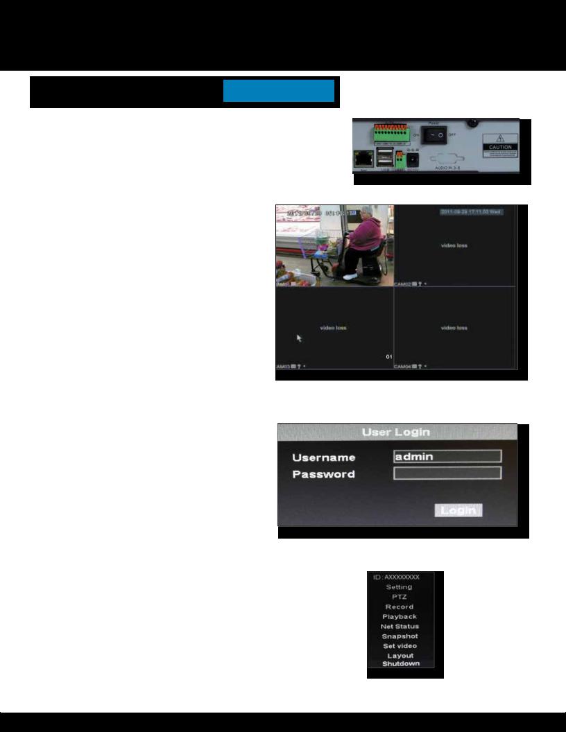
To power the system On/Off, connect the power cable to the DC 12V port on the rear panel. Flip the toggle switch on in the back of the DVR. At startup, the system performs a basic system check and runs an initial loading sequence. After a few moments, the system loads a live display view.
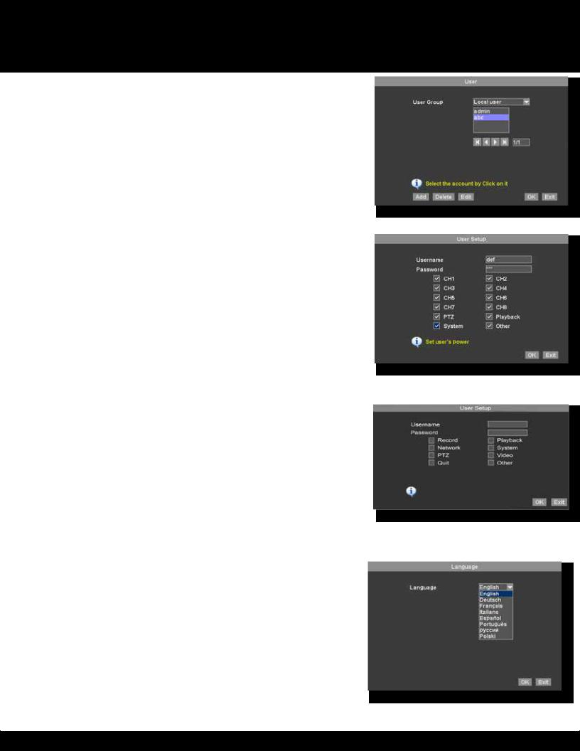
User Login
Password
ATTENTION: By default, passwords are disabled on the system. You do not need to enter a password when accessing any system menus. However, for security purposes, it is highly recommended to enable passwords on the system using the Password Menu. See “Password” section for details on setting up passwords. Right click and select Login. No password is required when no password is set up. Right click again to show the quick access menu
Quick Access Menu
When using the mouse, use the Quick Access Menu to access several system options, including the Main Menu. Select one of the following options:
•ID: Displays DVR ID#
•Setting: Opens the main system menu
•PTZ: Opens the PTZ control menu
•Record: Allows the user to start the record for any or all channels.
•Playback: Open the Search Menu and playback recorded video
•Net Status: Network status
•Snapshot: Allows you to take a snapshot of the channel that the cursor is on
•Set Video: Adjust video image brightness contrast and saturation by channel
•Layout: Provides a choice of viewing channels on the monitor
•Split 4 Allows viewing of channels 1 through 4
•Split 8 Allows viewing of channels 1 through 8, with channel 1 in large view mode
•Split 9 Allows viewing of channels in a 3 x 3 channel grid
•Shutdown: Allows a choice of logging out, powering down or restarting the DVR system
NOTE: Powering down stops the system. The power LED is still on. The only way to fully power down the system is by turning the power off & on with the power switch on the back of the DVR.
INITIAL SETUP
SYSTEM OPERATION
Power Switch
Main Viewing Screen
User Login Menu
Page 13

INITIAL SETUP
SYSTEM OPERATION
Setup (Main) Menu Access
To open the Main Menu: Right-click anywhere on-screen to open the Quick Access Menu and select Setting (mouse only), or press the Menu and select Setting on the remote control or front panel of the system.
NOTE: If passwords are enabled on the system, enter 1-10 alphanumeric password to enter the Setup menu.
Display: Allows user to set the placement of channel information |
|
Record: Allows the configuration of the recording parameters such |
|
as quality, audio and recording length. Note: Audio capable cameras |
|
(not included) are required for audio recording on the system. |
|
Network: Use to setup the network parameters for the DVR when |
Main Menu |
connected to a network. |
|
Picture: Use to search and view snapshots that have been taken in |
|
the system. |
|
Device: Opens the Device Setup Menu, which includes Alarm |
|
settings, look up system version information, motion detect, setting |
|
device IDs and configure PTZ, hard disk, video, IR. |
|
System: Open the System Menu, which lets you set the date & time, |
|
user accounts, system logs, system firmware update options, and |
|
system information, language. |
|
Password Setup
Setting Up User Permissions & Passwords
The system categorizes users into two main groups, Local and
Network.
•Local user: Refers to users who control host-end DVR
•Network User: Refers to users who control and view the DVR from a remote location via a wired or wireless network.
•Within the Network category, a Guest user can be created. Guest users will have access to channel viewing only.
When you first startup your DVR, you are automatically logged in as the ADMIN under local user and abc as the network user. .
•By default, local passwords are disabled on the system. You will not need a password to log in or access menus.
•The network admin user (abc) is set up with a password of ‘123’.
•For security reasons, it is highly recommended to enable passwords on your system. If you enable passwords, select a 1-10 alpha-numeric USER password.
•If you forgot your password, please contact First Alert Consumer Affairs @ 1-800-323-9005. A notarized letter will be needed for any password override.
Local USER Authorities as follows:
•ADMIN (administrator): Has full control of the system, and can change both administrator and user passwords, enable/disable password, and add or delete user authorities.
•Local USER (normal user): The user access is granted by the Admin.
Page 14
INITIAL SETUP
SYSTEM OPERATION
To Add a Local or Network User
To add or edit a new Local or Network User, from the Setup Menu, choose SYSTEM and then USER. Click ok to access this menu.
1.Choose Local or Network User Group.
2.Click ADD to create a new user.
3.Input new user name and password (required). The password is set by the Admin who is creating the new user.
4.Select user permissions by placing a check next to the action you are allowing access. Note: Granting SYSTEM access will allow the new user to change the settings of the DVR, including the settings of the ADMIN.
5.Click OK to confirm and Click OK on the User menu screen to exit.
To EDIT a Local or Network User
1.Choose Local or Network User Group.
2.Highlight the user you wish to edit.
3.Click EDIT to change user permissions.
4.Select/deselect user permissions by placing a check next to the action you are allowing access.
5.Click OK to confirm and Click OK on the User menu screen to exit.
To Delete a Local or Network User
Only those users with SYSTEM access can create or edit a user permission.
1.Choose Local or Network User Group.
2.Highlight the User to be deleted.
3.Click Delete. The system will ask you to confirm this action.
Record: Allows the USER to set the DVR to record (or not record) on one or all channels.
Network: Allows the USER to access the DVR via a remote networked connection.
PTZ: Allows the User to change PTZ parameter settings. Quit: Allows the User to power off or Restart the DVR.
Playback: Allows the USER to playback recorded video on the DVR.
System: Gives the USER ADMIN rights to change the setup of the DVR.
Video: User is allowed to change the video settings on the monitor screen from the drop down menu
Other: No function.
Modifying Passwords
An Admin – person with permission to system setup, has the ability to change their password as well as all others.
A User without permission to system setup access, must contact another user or administrator who has system setup access in order to change their password.
Language
The language is configurable. To set the language, from the SETUP menu select SYSTEM. Then select LANGUAGE. The following screen appears.
To change the system language: from the LANGUAGE drop down menu select the language amongst 8 different languages.
Click OK to apply. Click EXIT to close the menu.
Note: The system will change the language after a restart. A pop up box will ask if you want to perform a restart immediately or not. The default is English.
Permissions Screen
NETWORK USER Permission Screen
LOCAL USER Permission Screen
Use the virtual mouse to configure the options as desired.
Page 15
 Loading...