


)$ &36 )$ &3
6HFXULW\ 6\VWHPV
3URJUDPPLQJ *XLGH
ARMED
A |
1 |
|
|
B |
4 |
|
|
C |
7 |
|
|
D |
|
READY
2 |
3 |
5 |
6 |
|
|
8 |
9 |
|
|
0 |
# |
|
FA260
ARMED
ON |
OFF |
|
READY
AWAY STAY
PAGE
1OFF |
2AWAY |
|
|
4 MAX |
5 |
|
|
7 |
8CODE |
|
|
|
0 |
FA 5 6 0 |
|
3 6 9 #
K5305-5PRV2 10/03 Rev. A
TO ENTER PROGRAMMING MODE:
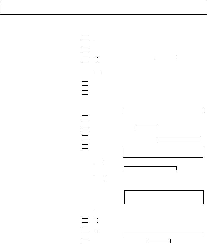
Local programming requires the use of an alpha keypad connected to the keypad terminals on the control.
A.POWER UP, then depress [ ] and [#] both at once, within 50 seconds of powering up (if 98 was used to exit program mode, this method must be used to reenter program mode).
OR
B.Initially, key: Installer Code (4 + 1 + 1 + 2) plus 8 + 0 + 0.
DATA FIELD PROGRAMMING PROCEDURES
Task |
Procedure |
Go to a Data Field |
Press [ ] + [Field Number], followed by the required entry. |
Entering Data |
When the desired field number appears, simply make the required entry. When the last entry for a |
|
field is entered, the keypad beeps three times and automatically displays the next data field in |
|
sequence. |
|
If the number of digits that you need to enter in a data field is less than the maximum digits available |
|
(for example, the phone number fields *41, *42), enter the desired data, then press [ ] to end the |
|
entry. The next data field number is displayed. |
|
|
Review a Data Field |
Press [#] + [Field Number]. |
|
Data will be displayed for that field number. No changes will be accepted in this mode. |
Deleting an Entry |
Press [ ] + [Field Number] + [ ]. (Applies only to fields 40 thru *46, *94, and pager programming |
|
fields) |
INTERACTIVE MODE PROGRAMMING ( 56, 57, 58, 79, 80, 81, 82, 187)
Press [ ] + [Interactive Mode No.] (for example, 56). The alpha display keypad will display the first of a series of prompts requesting entries.
Interactive Mode |
Used to Program |
|
56 Zone Programming |
Zone characteristics, report codes, alpha descriptors, and serial numbers for 5800 RF |
|
|
|
transmitters. |
|
|
|
57 Function Key Programming |
Unlabeled keypad keys (known as ABCD keys) for special functions |
|
|
|
|
58 Zone Programming |
Same options as *56 mode, but with fewer prompts. Intended for those familiar with |
|
(Expert mode) |
this type of programming, otherwise *56 mode is recommended. |
|
|
|
|
79 |
Output Device Mapping |
Assign module addresses and map individual relays/powerline carrier devices |
|
|
|
80 |
Output Programming |
4229 or 4204 Relay modules, Powerline Carrier devices, or on-board triggers |
81 |
Zone List Programming |
Zone Lists for relay/powerline carrier activation, chime zones, pager zones, etc. |
82 |
Alpha Programming |
Zone alpha descriptors |
INITIALIZE DOWNLOAD and RESET DEFAULTS
96 Initializes download ID and subscriber account number.97 Sets all data fields to original factory default values.
TO EXIT PROGRAMMING MODE:
98 Exits programming mode and prevents re-entry by: Installer Code + 8 + 0 + 0. If 98 is used to exit programming mode, system must be powered down, and method A above used to enter the programming mode.
See field *88 for other *98 Program mode lockout options.
99 Exits programming mode and allows re-entry by: Installer Code + 8 + 0 + 0 or method 1 above.
Special Messages
OC = OPEN CIRCUIT (no communication between Keypad and Control).
EE or ENTRY ERROR = ERROR (invalid field number entered; re-enter valid field number).
After powering up, AC, dI (disabled) or Busy Standby and NOT READY will be displayed after approximately 4 seconds. This will revert to a “Ready” message in approximately 1 minute, which allows PIRS, etc. to stabilize. You can bypass this delay by pressing [#] + [0].
If E4 or E8 appears, more zones than the expansion units can handle have been programmed. The display will clear after you correct the programming.
– 2 –
352*5$00,1* )250
Entries apply to both the FA168CPS and FA148CP controls, except entries shown in dashed boxes, which apply only to the FA168CPS (partition entries) and are not applicable to the FA148CP.
Entry of a number other than one specified will give unpredictable results. Values shown in brackets are factory defaults.
Field |
Function |
Data Entries |
|
Programmable Values |
||||
SYSTEM SETUP ( 20– 29) |
|
|
|
|
|
|
|
|
20 |
INSTALLER CODE |
|
|
|
|
|
4 digits, 0–9 |
|
|
| | | |
|
[4112] |
|||||
|
|
|
|
|
|
|
||
21 |
QUICK ARM ENABLE |
[0,0] |
|
0 = no; 1 = yes |
||||
|
|
|
|
|
||||
|
|
Part. 1 Part.2 |
|
|
|
|
||
22 |
RF JAM OPTION |
[0] |
|
|
|
0 = no RF Jam detection; 1 = send RF Jam report |
||
|
|
|
|
|
UL: must be 1 if wireless devices are used |
|
||
|
|
|
|
|
|
|
|
|
23 |
QUICK (FORCED) BYPASS |
|
|
[0,0] |
|
|
|
|
|
|
|
|
|
Part. 1 Part. 2 |
|
||
24 |
RF HOUSE ID CODE |
|
|
|
|
| |
|
| |
| |
||
|
|
|
|||
|
|
Part. 1 |
Part. 2 |
Common |
|
26 |
CHIME BY ZONE |
[0] |
|
||
|
|
|
|||
27 |
POWERLINE CARRIER DEVICE (X–10) |
|
|
[0] |
|
|
HOUSE CODE |
|
|
|
|
|
|
|
|
|
|
28 |
ACCESS CODE FOR |
|
|
|
|
| |
|
[00] |
|
||
|
PHONE MODULE |
|
|
||
|
(Partition 1 only) |
|
|||
|
|
|
|||
29 |
LONG RANGE RADIO OUTPUT |
[0] |
|
||
|
|
|
|||
ZONE SOUNDS AND TIMING ( 31 – 39) |
|
|
|
|
|
31 |
SINGLE ALARM SOUNDING per ZONE |
|
|
[0] |
|
|
|
|
|
|
|
32 |
FIRE ALARMSOUNDER TIMEOUT |
|
|
[0] |
|
|
|
|
|
|
|
33 |
ALARM SOUNDER (BELL) TIMEOUT |
|
|
[1] |
|
|
|
|
|
|
|
0 = no quick bypass UL: must be “0”
1 = allow quick bypass (code + [6] + [#] )
00 = disable all wireless keypad usage
01–31 = using 5827, 5827BD or 5804BD keypad [00,00,00]
0 = no; 1 = yes (select zones to chime on zone list 3, using *81 Menu mode)
0 |
= A; 1 = B, 2 = C, 3 = D, 4 = E, 5 = F, 6 = G, |
|||
7 |
= H, 8 = I, 9 |
= J, #10 = K, #11 = L, #12 = M, #13 = N, |
||
#14 = O, #15 |
= P |
UL: not for fire or UL installations |
|
|
00 = disable; 1st digit: enter 1–9; 2nd digit: enter # + 11 for " ", or # + 12 for "#".
UL: must be “00” for UL Commercial Burg. installations
0 = disable; 1 = enable
0 = no UL: must be “0”; 1 = yes
0 = sounder stops at timeout;
1 = no sounder timeout UL: must be “1” for fire install.
0 = none; 1 = 4 min; 2 = 8 min; 3 =12 min; 4 = 16 min;
UL: For residential fire alarm installation, must be set for a minimum of 4 min (option 1); for UL Commercial Burglary installations, must be minimum 16 min (option 4)
34 |
EXIT DELAY |
|
|
|
|
|
| |
| |
[60,60] |
||
|
|
|
|||
|
|
Part. 1 |
Part. 2 |
|
|
35 |
ENTRY DELAY #1 (zone type 01) |
|
|
|
|
|
| |
| |
[30,30] |
||
|
|
|
|||
|
|
Part. 1 |
Part. 2 |
|
|
|
|
|
|
||
|
|
|
Common zones use same |
||
|
|
|
delay as partition 1. |
||
00 - 96 = 0 - 96 secs; 97 = 120 secs
SIA Installations: minimum exit delay is 45 seconds UL: see inst. instr. for requirements.
Common zones use same delay as partition 1.
00 |
- 96 = 0 - 96 seconds |
|
97 |
= 120 seconds |
SIA Installations: |
98 |
= 180 seconds |
minimum entry delay is |
99 |
= 240 seconds |
30 seconds |
For UL Residential Burglary Alarm installations, must be set for a maximum of 30 seconds; entry delay plus dial delay should not exceed 1 min. For UL Commercial Burglar Alarm, total entry delay may not exceed 45 seconds.
36 |
ENTRY DELAY #2 (zone type 02) |
|
|
|
|
| |
| |
[30,30] |
|||
|
|
||||
|
|
Part. 1 |
Part. 2 |
|
|
37 |
AUDIBLE EXIT WARNING |
|
[1,1] |
|
|
|
|
|
|
||
38 |
CONFIRMATION OF ARMING DING |
|
[0,0] |
|
|
|
|
|
|
||
|
|
Part. 1 |
Part. 2 |
|
|
39 |
POWER UP IN PREVIOUS STATE |
|
[1] |
|
|
|
|
|
|
See *35 Entry Delay 1 above for entries.
0 = no; 1 = yes
SIA Installations: must be enabled (enter 1)
0 = no; 1 = yes (wired keypads and RF) 2 = yes, RF only
UL: must be “1” for UL Commercial Burglar Alarm inst.
0 = no; 1 = yes UL: must be “1”
DIALER PROGRAMMING ( 40 – 42)
Do not fill unused spaces. Enter 0–9; #+11 for ' '; #+12 for '#'; #+13 for a 2-second pause. If fewer than the maximum digits entered, exit the field by pressing [ ]. The next data field number is displayed.
40 |
PABX ACCESS CODE |
|
|
|
|
|
|
|
|
|
|
|
Enter up to 6 digits. To clear entries, press 40 . If call waiting |
|||||||||
|
|
|
|
|
|
| |
| |
| |
| |
| |
|
|||||||||||
|
|
|
|
|
|
|
used, enter “ (#+11) 70” plus “# + 13” (pause). |
|||||||||||||||
41 |
PRIMARY PHONE No. |
|
|
|
|
|
|
|
|
|
|
|
|
|
|
|
|
|
|
|
|
|
| |
| |
| |
| |
| |
| |
| |
| |
| |
| |
| |
| |
| |
| |
| |
| |
| |
| |
| |
|
|||
42 |
SECOND PHONE No. |
|
|
|
|
|
|
|
|
|
|
|
|
|
|
|
|
|
|
|
|
|
| |
| |
| |
| |
| |
| |
| |
| |
| |
| |
| |
| |
| |
| |
| |
| |
| |
| |
| |
|
|||
|
|
Enter up to 20 digits. To clear entries, press 41 or |
42 respectively. |
|||||||||||||||||||
– 3 –

NOTE: Entry of a number other than one specified will give unpredictable results.
For fields *43 thru *46: Enter 0–9; #+11 for B; #+12 for C; #+13 for D; #+14 for E; #+15 for F. Enter [ ] as the fourth digit if a 3-digit account number (for 3+1 dialer reporting format) is used. Enter 0 as the first digit of a 4-digit account number for Nos. 0000-0999. Exit field by pressing if only 3 digits are used. E.g., For Acct.
B234, enter: #+11| 2 | 3 | 4
43 PARTITION 1 PRIMARY ACCT. No.
44 PART. 1 SECONDARY ACCT. No.
45 PARTITION 2 PRIMARY ACCT. No.
46 PARTITION 2 SECONDARY ACCT. No.
47 PHONE SYSTEM SELECT
48 REPORT FORMAT
49 SPLIT/DUAL REPORTING
50 BURGLARY DIALER DELAY
53 SESCOA/RADIONICS SELECT
54 DYNAMIC SIGNALING DELAY
55 DYNAMIC SIGNALING PRIORITY
56, *57, *58 MENU MODES
| |
|
| |
| |
/ |
| |
| |
| |
| |
| |
|
|
|
|
|
|
|
|
|
|
|
|
| |
|
| |
| |
/ |
| |
| |
| |
| |
| |
|
| |
| |
| |
|
/ |
| |
| |
| |
| |
| |
|
| |
| |
| |
|
/ |
| |
| |
| |
| |
| |
|
|
|
|
|
|
[1] |
|
|
|
|
|
|
|
|
|
|
|
|
|
|
|
|
|
|
|
|
|
|
|
|
|
[77] |
|
|
|
|
|
|
|
|
|
|
||
|
primary |
secondary |
||||||||
[0]
Enter 4 or 10 digits, depending on selection in *48 Report Format. See box above. To clear entries, press *43*. [FFFF] Enter 4 or 10 digits, depending on selection in *48 Report Format. See box above. To clear entries, press *44*. [FFFF] Enter 4 or 10 digits, depending on selection in *48 Report Format. See box above. To clear entries, press *45*. [FFFF] Enter 4 or 10 digits, depending on selection in *48 Report Format. See box above. To clear entries, press *46*. [FFFF]
If Cent. Sta. IS NOT on a WATS line: 0=Pulse; 1=Tone; if Cent. Sta. IS on a WATS line: 2 = Pulse; 3 = Tone
0 |
= 3+1, 4+1 ADEMCO L/S STANDARD |
|||||
1 |
= 3+1, 4+1 RADIONICS STANDARD |
|||||
2 |
= 4+2 ADEMCO L/S STANDARD |
|||||
3 |
= 4+2 RADIONICS STANDARD |
|
|
|||
5 |
= 10-digit ADEMCO CONTACT ID® REPORTING |
|||||
6 |
= 4+2 ADEMCO EXPRESS |
|
|
|
|
|
7 |
= 4-digit ADEMCO CONTACT ID® REPORTING |
|||||
8 |
= 3+1, 4+1 ADEMCO L/S EXPANDED |
|||||
9 |
= 3+1, 4+1 RADIONICS EXPANDED |
|||||
0 |
= Standard/backup reporting only (all to primary) |
|||||
|
|
Primary Phone No. |
2nd Phone No. |
|
||
1 |
= Alarms, Restore, Cancel |
|
|
Others |
||
2 |
= All except Open/Close, Test |
|
Open/Close, Test |
|||
3 |
= Alarms, Restore, Cancel |
|
|
All |
||
4 |
= All except Open/Close, Test |
|
All |
|||
5 |
= All |
|
|
All |
||
[2] |
0 |
= no delay |
UL: must be “0” |
|
|
|
1 |
= 15 seconds |
|
SIA Installations: delay |
|
|
2 |
= 30 seconds |
|
must be minimum of |
|
|
3 |
= 45 seconds |
|
30 seconds |
|
[0] |
0 = Radionics (0-9, B-F) |
|
|
1 = SESCOA (0-9 only reporting) |
|
||
|
|
||
|
Select “0” for all other formats. |
|
|
[0] |
Select delay from 0 to 225 secs, in 15-sec increments. |
|
|
0 |
= no delay (both signals sent), 1 = 15 secs, |
|
|
|
|
||
|
2 |
= 30 secs, etc. |
|
|
UL: Grade AA must be “0;” Grade A must be “15” max |
|
|
[0] |
0 |
= Primary Dialer first; 1 = Long Range Radio first. |
|
|
For UL Commercial Burglary installations that use a |
|
|
|
|
|
|
|
|
DACT and LRR, this field must be “0”. |
|
These are Menu Mode commands, not data fields, for Zone Programming, Function Key Programming, and Expert Mode Zone Programming respectively. See page 2 and their respective sections in the Installation and Setup Guide for procedures.
TO PROGRAM SYSTEM STATUS, & RESTORE REPORT CODES ( 59 thru *68, *70 thru 76, and 89):
For 3+1 or 4+1 Standard Format: Enter a code in the first box: 1–9, #+10 for 0, #+11 for B, #+12 for C, #+13 for D, #+14 for E, #+15 for F. A 0 (not #+10) in the first box will disable a report. A 0 (not #+10) in the second box will result in automatic advance to the next field.
For Expanded or 4+2 Format: Enter codes in both boxes (1st and 2nd digits) for 1–9, 0, or B–F, as described above.
A 0 (not #+10) in the second box will eliminate the expanded message for that report. A 0 (not #+10) in both boxes will disable the report.
For Ademco Contact ID® Reporting: Enter any digit (other than 0) in the first box, to enable zone to report (entries in the second boxes are ignored).
A 0 (not #+10) in the first box disables the report. UL: see installation instructions for requirements
SYSTEM STATUS REPORT CODES ( 59– 68) |
|
|
|
|
||
59 EXIT ERROR REPORT CODE |
|
[0] |
See box above. |
|||
60 TROUBLE REPORT CODE |
|
|
|
[00] |
See box above. |
|
|
| |
|
||||
61 |
BYPASS REPORT CODE |
|
|
|
See box above. |
|
|
| |
|
[00] |
|||
62 |
AC LOSS REPORT CODE |
|
|
|
See box above. |
|
|
| |
|
[00] |
|||
63 |
LOW BAT REPORT CODE |
|
|
|
See box above. |
|
|
| |
|
[00] |
|||
64 |
TEST REPORT CODE |
|
|
|
See box above. Use Scheduling mode to set periodic test reports, |
|
|
| |
|
[00] |
|||
Each mode sets schedule 32 (FA168CPS) or schedule 08 (FA148CP) to the stated
repeat option; first test report sent 12 hours after command.
or use the following key commands:
installer code +[#] + [0] + 0 = test report sent every 24 hours installer code +[#] + [0] + 1 = test report sent once per week installer code +[#] + [0] + 2 = test report sent every 28 days
– 4 –

65 |
OPEN REPORT CODE |
|
|
[0,0,0] |
See box above. |
|
|
Part. 1 |
Part. 2 Common |
|
|
66 |
ARM AWAY/STAY RPT CODE |
|
|
|
[0,0,0,0,0,0] See box above. |
|
Away Stay |
Away Stay |
Away Stay |
||
|
|
Part. 1 |
Part. 2 |
Common |
|
67 |
RF XMTR LOW BAT REPORT CODE |
|
[00] |
See box on previous page. |
|
|
| |
||||
UL: must be enabled if wireless devices are used
68 CANCEL REPORT CODE
RESTORE REPORT CODES ( 70 – 76)70
71
72
73
74
75
76
OUTPUT AND SYSTEM SETUP ( 77 – 93)
77 DAYLIGHT SAVINGS TIME START\END MONTH
78 DAYLIGHT SAVINGS TIME START\END WEEKEND
79, *80, *81, *82 MENU MODES
84 AUTO STAY ARM
85 CROSS ZONE TIMER
This option not for use in UL installations.
86 CANCEL VERIFY KEYPAD DISPLAY
87 MISC. FAULT DELAY TIME
(used with Configurable Zone Types “digit 6”)
| |
|
|
[00] |
|
See box on previous page. |
|
|
[0] |
|
|
See box on previous page. |
||
|
|
|
||||
|
|
|
[00] |
|
See box on previous page. |
|
| |
|
|
|
|||
|
|
|
[00] |
|
See box on previous page. |
|
| |
|
|
|
|||
|
|
|
[00] |
|
See box on previous page. |
|
| |
|
|
|
|||
|
|
|
[00] |
|
See box on previous page. |
|
| |
|
|
|
|||
|
|
|
[00] |
|
See box on previous page. |
|
| |
|
|
|
|||
|
|
|
|
|
|
|
|
|
|
|
|
UL: must be enabled if wireless devices are used |
|
|
|
|
[00] |
|
See box on previous page. |
|
| |
|
|
|
|||
|
|
|
|
0 = Disabled |
||
| |
|
|
[4][10] |
|||
|
|
1-12 = January-September (1 = Jan, 2 = Feb, etc) |
||||
|
|
|
|
|||
|
|
|
|
#+10 = October; #+11 = November; #+12 = December |
||
|
|
|
|
0 = disabled, 1 = first, 2 = second, 3 = third |
||
| |
|
|
[1][5] |
|||
|
|
4 = fourth, 5 = last, 6 = next to last, 7 = third to last |
||||
|
|
|
|
|||
These are Menu Mode commands, not data fields, for Output Device Mapping, Output Programming, Zone List Programming, and Alpha Programming respectively. See page 2 and their respective sections in the Installation and Setup Guide for procedures.
[3]
[0]
(assign cross zones on zone list 4, using *81 Menu mode)
[1]
[0]
UL: may only be used on non-burglar alarm/ non-fire alarm zones when used in fire and/or UL burglar alarm installation
0 = no, 1 = partition 1 only
2 = partition 2 only, 3 = both partitions
0 |
= 15 seconds |
6 |
= 2-1/2 min |
#+12 = 8 min |
1 |
= 30 seconds |
7 |
= 3 min |
#+13 = 10 min |
2 |
= 45 seconds |
8 |
= 4 min |
#+14 = 12 min |
3 |
= 60 seconds |
9 |
= 5 min |
#+15 = 15 min |
4 |
= 90 seconds |
#+10 = 6 min |
|
|
5 |
= 2 minutes |
#+11 = 7 min |
|
|
0 |
= no, 1 = yes |
|
|
|
0 |
= 15 seconds |
6 |
= 2-1/2 min |
#+12 = 8 min |
1 |
= 30 seconds |
7 |
= 3 min |
#+13 = 10 min |
2 |
= 45 seconds |
8 |
= 4 min |
#+14 = 12 min |
3 |
= 60 seconds |
9 |
= 5 min |
#+15 = 15 min |
4 |
= 90 seconds |
#+10 = 6 min |
|
|
5 |
= 2 minutes |
#+11 = 7 min |
|
|
88 PROGRAM MODE LOCKOUT OPTIONS
89 EVENT LOG FULL REPORT CODE
90 EVENT LOG ENABLES
91 OPTION SELECTION
[0]
| [00]
[3]
NOTE: System messages are logged when any non-zero selection is made.
[8]
SIA Installations: Exit Delay should be enabled.
0 = standard *98 installer code lockout (reentry only by downloader or [ ] + [#] within 50 secs after power up)
1 = lockout [ ] + [#] reentry after *98 exit (reenter via installer code or downloader only)
2 = not used
3 = lockout all local programming after *98 exit (reentry via downloader only)
See box on previous page for report code entries.
0 = None; 1 = Alarm/Alarm Restore
2 = Trouble/Trouble Restore;
4 = Bypass/Bypass Restore;
8 = Open/Close.
Example: To select “Alarm/Alarm Restore”, and “Open/Close”, enter 9 (1 + 8); To select all, enter #15.
0 = None
2 = Sounder Delay (delays sounding by 15 seconds) UL: if used, entry delay (*35) must be 30 sec. max.
4 = AAV UL: must use ADEMCO UVCM module
8 = Exit Delay Restart/Reset UL: must be disabled #+12 = AAV and Exit Delay Restart/Reset
– 5 –
 Loading...